PRE-RELEASE
Bearing housing cover gasket, to removal and fitting
| Bearing housing cover gasket, to removal and fitting |
| To remove |
| 1. |
Place drapes over the wings to keep the paintwork clean and protect it from damage.
|
|
| 2. |
Remove the upper engine cover and the battery cover.

|
|
| 3. |
Disconnect the battery terminals and remove the battery.
|
|
| 4. |
Undo the cable clamp under the battery tray.
|
|
| 5. |
Unplug the bonnet switch connector.
|
|
| 6. |
Remove the battery tray.

|
|
| 7. |
Undo the ground cable from the engine mounting
|
|
| 8. |
Remove the clutch cables from the gearbox
Undo the gear selector cables (1) from the gear cover (2) 2x Remove from the support 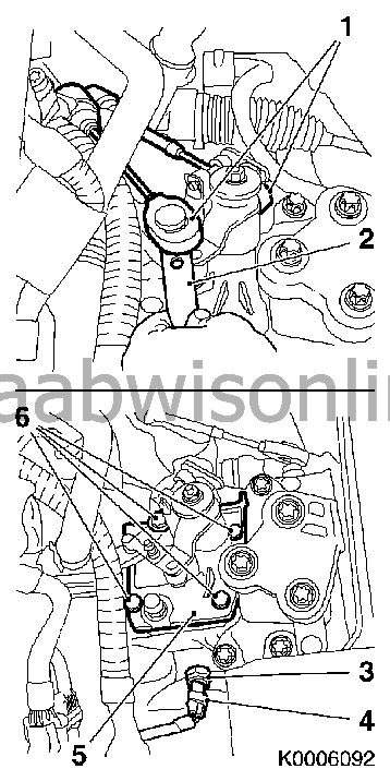
|
|
| 9. |
To remove the gear change unit (5)
4x Unscrew bolts (6) Remove the gearchange unit |
|
| 10. |
Remove the reversing light switch
Remove the wiring loom connector (4) Unscrew the reversing light switch (3) |
|
| 11. |
Fit
83 94 850 Lifting beam
.
|
|
| 12. |
Remove the front engine mount
Undo bolt (2) from the front suspension frame 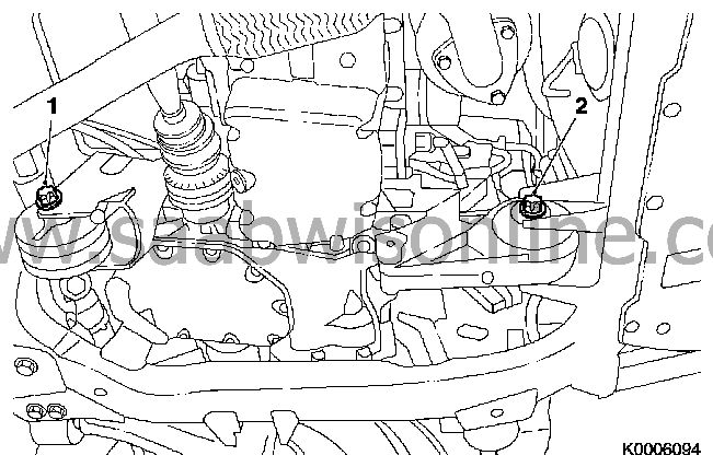
|
|
| 13. |
Remove the rear engine mount
Undo the bolt (1) from the front suspension frame |
|
| 14. |
Remove the LH front wheel
5x Unscrew bolts |
|
| 15. |
If fitted: Remove the front sensor for headlight adjustment
|
|
| 16. |
Remove the LH engine mount
3x Unscrew bolts (3) Important: Check that the engine and engine components are not resting against the front suspension frame or subframe. Cables and hoses must not be stretched. |
|
| 17. |
Lower the engine/gearbox
Lower using lifting beam 83 94 850 Lifting beam , until the bearing housing is not up against the front suspension frame or subframe whilst removing |
|
| 18. |
To remove the bearing housing cover
Put an oil tray underneath as oil will run out 9x Unscrew bolts Note: If necessary: Free the bearing housing cover with light taps of a rubber hammer. Collect any oil that runs out Remove the gasket. 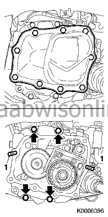
|
|
| 19. |
Screw in a guide pin
Screw in 87 92 962 Guide pins gearcase 2x F17 (1) Note: These are used to guide the bearing housing so as to avoid damage to the central clutch sealing ring. |
|
| 20. |
To remove the bearing housing from the gearbox
Put an oil tray underneath as oil will run out 4x Remove bolts (arrowed) |
|
| 21. |
Remove the bearing housing
Carefully lift away the bearing housing Note the magnet (2) and spacer (1) of the reverse gear shaft Note: Remove if necessary 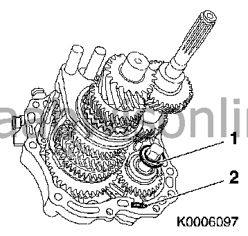
|
|
| 22. |
Remove the gasket.
|
|
| 23. |
Check for damage and wear on all components
|
|
| 24. |
Remove all traces of sealant and clean the mating surfaces.
To fit |
|
| 25. |
To fit the bearing housing
Fix a new gasket in place onto the gearcase sealing surface using grease. Carefully assemble the bearing housing to the gearcase Directions: Note the magnet (2) and spacer (1) of the reverse gear shaft
|
|
| 26. |
Tighten the bearing housing
4x Screw tight using new bolts (arrowed) (22Nm) Remove 87 92 962 Guide pins gearcase 2x F17 (1) 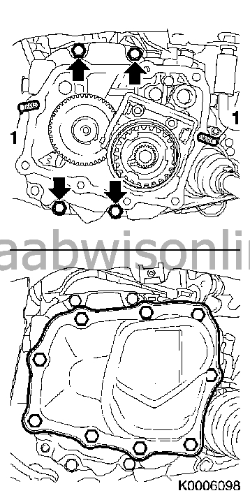
|
|
| 27. |
Fit the bearing housing cover
Assemble using a new gasket on the gearcase 4x Tighten the bolts - M7 (15 Nm) 5x Tighten the bolts - M8 (20 Nm) |
|
| 28. |
Where appropriate: Fit the front sensor for headlight adjustment
|
|
| 29. |
Fit the LH engine mount
Raise into position using 83 94 850 lifting beam 3x Fit the mounting bolts (3) for the LH engine mount but do not tighten yet Note: The engine mount must remain loose until the engine/gearbox has been adjusted Important: Do not adjust the support bearing |
|
| 30. |
Put in place KM-6313 (
83 96 145 Centring jig, subframe - engine
) with
83 96 368 Supplementary set for centring jig
(1) in the front subframe
Note: In order to ensure that the drive train is correctly adjusted when the engine mount bolts have been loosened, the drive train must be positioned relative to the front subframe. Insert 83 96 376 Adapter set sleeves x4 . The pins (3, 6) must be located in the guide holes in the front subframe 2x Tighten the adjustment rail bolts (arrowed) The rear support bearing (4) must locate in the guide pin on the rear engine mount holder without any free-play The front support bearing (5) must locate in the guide pin on the front engine mount without any free-play 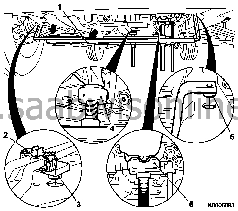
|
|
| 31. |
Lower the engine/gearbox with
83 94 850 Lifting beam
Note: The engine mount guide bearing and holder must locate in the support bearing (3, 4)
|
|
| 32. |
Fit the LH engine mount
Tighten the three LH engine mount bolts (1) (55 Nm)
|
|
| 33. |
Fit the front engine mount
Tighten bolt (2) with a new nut on the front suspension frame ( 80 Nm) |
|
| 34. |
Fit the rear engine mount
Tighten the bolt (1) on the engine mount holder (80 Nm) |
|
| 35. |
Remove
83 96 145 Centring jig, subframe - engine
(1)
Screw back the support bearing (2, 3) 2x Undo the adjustment rail bolts (arrowed) 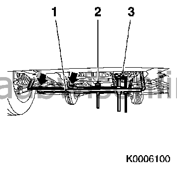
|
|
| 36. |
Fit the gearchange unit (2)
Assemble with a new gasket 4x Tighten the bolts (1) (15 Nm) 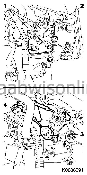
|
|
| 37. |
Assemble the gear selector cables to the gearbox
2x Fit into the support (4) Attach the gear selector cables (3) to the gear cover |
|
| 38. |
Adjust the oil level in the gearbox
see service procedure Gearbox oil level, checking and correcting F17 . |
|
| 39. |
Check that all gears run smoothly
when the car is stationary with the engine running and with the clutch disengaged. |
|
| 40. |
Fit the reversing light switch (1)
Assemble with a new sealing ring Tighten the reversing light switch (20 Nm) Replace the wiring loom connector (2) 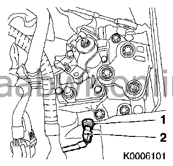
|
|
| 41. |
Attach the ground cable to the engine mounting. Tightening torque 18 Nm (13 lbf ft)
|
|
| 42. |
Fit the battery tray and the bonnet switch connector.
|
|
| 43. |
Fit the battery.
|
|
| 44. |
Fit the battery cover and upper engine cover.
|
|
| 45. |
Remove the wing covers.
|
|
| 46. |
Fit the wheel. See
Wheels
|
|
| 47. |
Carry out
Measures after disconnecting the battery
.
|
|
