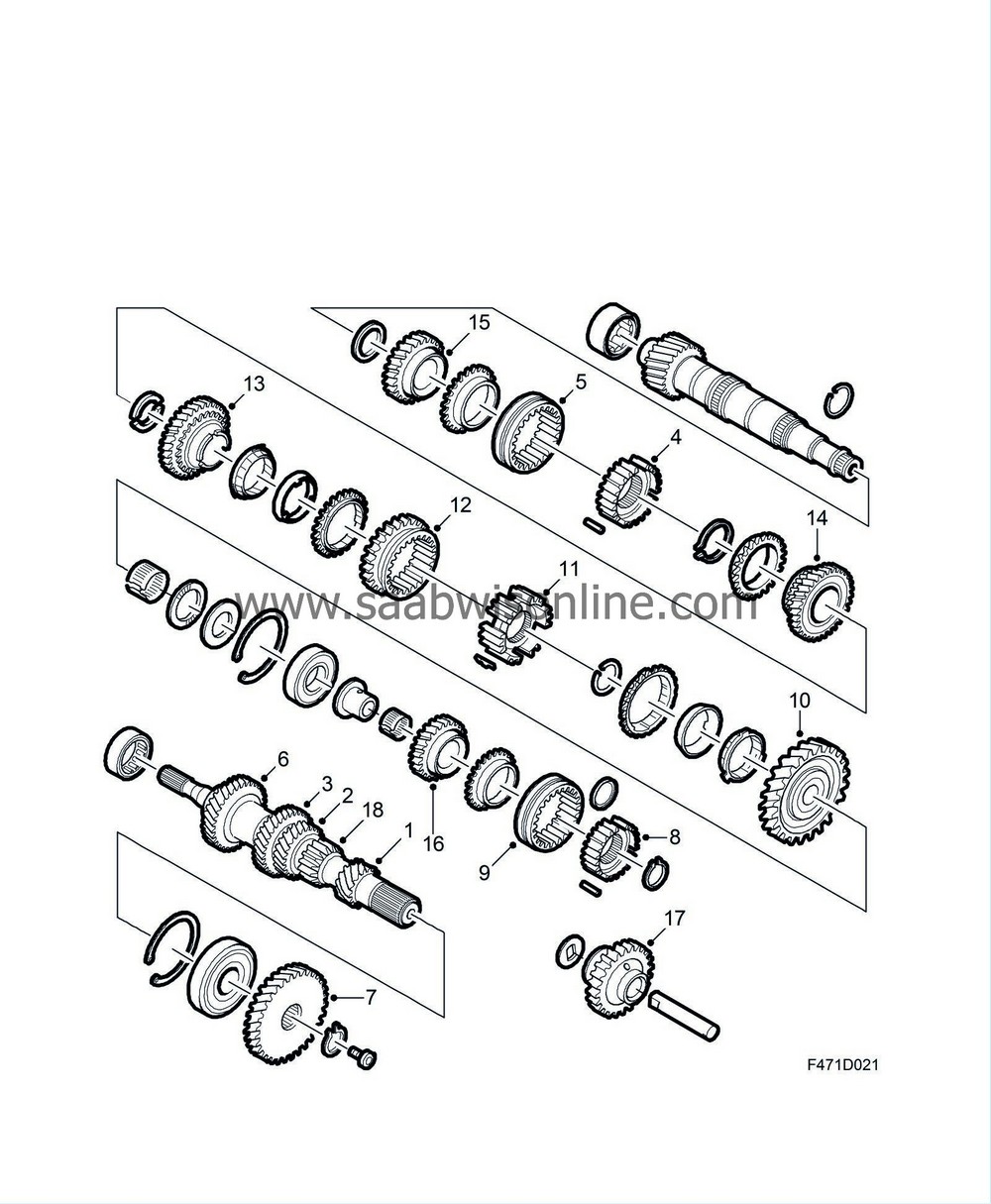
PRE-RELEASE
Detailed description
| Detailed description |
| 1. |
Pinion, 1st gear
|
|
| 2. |
Pinion, 2nd gear
|
|
| 3. |
Pinion, 3rd gear
|
|
| 4. |
Synchromesh hub, 3rd-4th gear
|
|
| 5. |
Synchromesh sleeve, 3rd-4th gear
|
|
| 6. |
Pinion, 4th gear
|
|
| 7. |
Pinion, 5th gear
|
|
| 8. |
Synchromesh hub, 5th gear
|
|
| 9. |
Synchromesh sleeve, 5th gear
|
|
| 10. |
Gear wheel, 1st gear
|
|
| 11. |
Synchromesh hub, 1st-2nd gear
|
|
| 12. |
Synchromesh sleeve, 1st-2nd gear
|
|
| 13. |
Gear wheel, 2nd gear
|
|
| 14. |
Gear wheel, 3rd gear
|
|
| 15. |
Gear wheel, 4th gear
|
|
| 16. |
Gear wheel, 5th gear
|
|
| 17. |
Reverse gear wheel
|
|
| 18. |
Reverse pinion
|
|
The manual gearbox has 5 forward gears, all of which have synchromesh. The gearbox is not fitted with a reverse brake. The gearbox has, relative to its capacity, small rotating masses and thus the inertial energy which must be dissipated at every gear change has been kept to a minimum. Consequently gear changing is easy and smooth and the wear on the synchromesh baulk rings and sleeves is almost negligible.
The baulk rings are fitted to the output shaft. Note that the gears on the input shaft are called a pinions (are driving) whilst the gears on the output shaft are called gear wheels (are driven). All the gear wheels are fitted with needle roller bearings to give high efficiency by minimising friction losses.
In order to improve the synchromesh function the first and second gears are fitted with two baulk rings. The input and output shafts have roller bearings at both ends. Power from the engine is transmitted via the clutch directly to the input shaft.
Transmission
Transmission in 1st gear: In 1st gear power is transmitted from the input shaft via the 1st gear pinion to the 1st gear wheel which is locked to the output shaft by the 1st/2nd synchromesh assembly.Transmission is effected in the same manner for all the forward gears with the respective pinions being located on the input shaft and the respective gear wheels on the output shaft.
Transmission in reverse. This is achieved by means of an extra shaft (reverse idler shaft). A reverse gear wheel, fitted with a bearing, is located on the shaft and is not engaged unless reverse gear is selected. When reverse is selected, this gear wheel is slid into mesh with both the reverse pinion on the input shaft and the 1st/2nd synchromesh sleeve, which incorporates a gear wheel and is locked to the output shaft via the 1st/2nd synchromesh hub. As the power is thus transmitted from the input to the output shaft via a third (idler) gear, the desired reversed rotation is achieved.
Operation
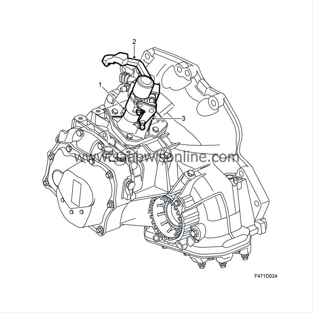
Between the selector lever shaft (1) in the gearbox and the gear lever is a cable and lever arrangement which transfers torque and transverse shearing force from gear lever to selector lever shaft.Two levers are mounted in bearings on the gearcase. One is for rotating the selector lever shaft so that the respective selector fork is correctly positioned and the other is for sliding the selector lever shaft in the appropriate direction in order to move the selector fork and dog. Both selector cables are attached to the levers with ball and socket joints and are routed through grommets in the bulkhead to the gear lever. The use of cables prevents movements and vibrations from the power train being transmitted to the gear lever and body.
| 1. |
Selector shaft
|
|
| 2. |
Gear selector arm, turn
|
|
| 3. |
Selector lever arm, push then pull
|
|
In order to select reverse gear (R), a locking button under the gear lever knob must be lifted. In the neutral position the gear lever, because of spring tensions within the gearbox, strives to take up a position just between 3rd and 4th gear. This helps the driver to sense the position of the gear lever and to avoid incorrect gear selection.
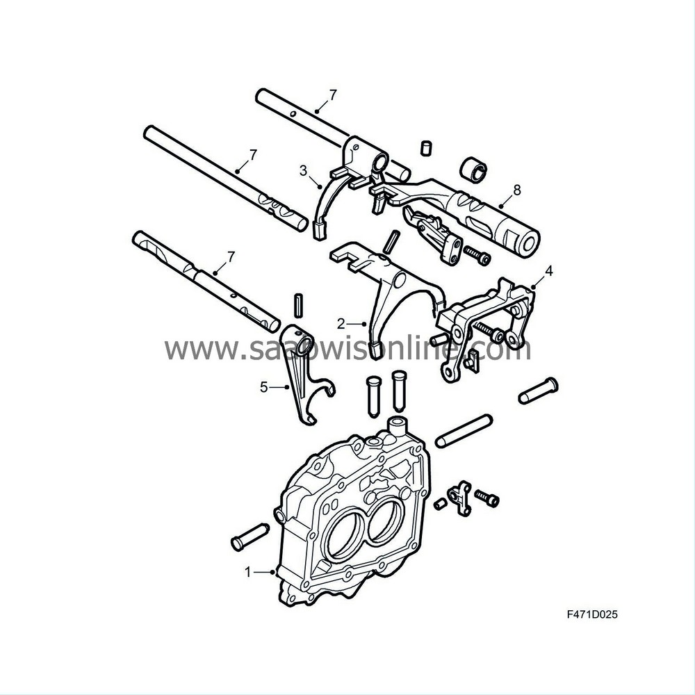
In order to prevent the engagement of more than one gear at a time, the gearbox is fitted with a selector interlock device. This incorporates two locking pins and a catch. One locking pin slides in a track between the reverse and 1st/2nd gear selectors and the other is positioned between the 1st/2nd and 3rd/4th gear selectors. The catch is mounted on the selector rod for the 3rd/4th and 5th gears. When a gear is selected the respective locking pin or catch is slid to a position which prevents the other gear selector components from moving.
| 1. |
Bearing housing
|
|
| 2. |
Selector fork, 1-2
|
|
| 3. |
Selector fork, 3-4
|
|
| 4. |
Selector fork, 5
|
|
| 5. |
Selector fork, reverse
|
|
| 6. |
Catch
|
|
| 7. |
Selector rods
|
|
| 8. |
Selector dog
|
|
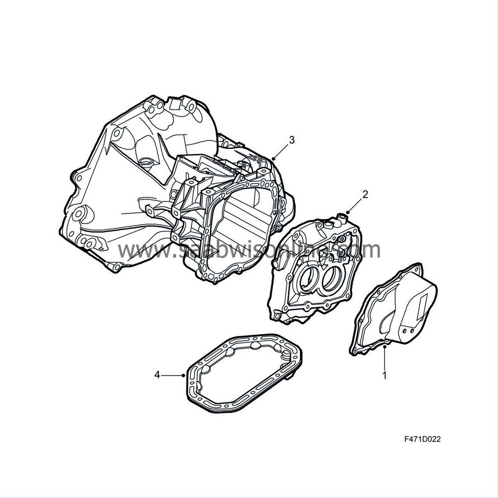
Mating face
| 1. |
End cover
|
|
| 2. |
Bearing housing
|
|
| 3. |
Gearcase and clutch housing
|
|
| 4. |
Differential cover
|
|
The gearbox has a mating face between the gearcase and the bearing housing. There are two covers, one on the bearing housing and one under the differential housing. All the mating faces are sealed with gaskets.
Ventilation and bleeding takes place by means of a hole in a plug fitted in the gear selector cover.
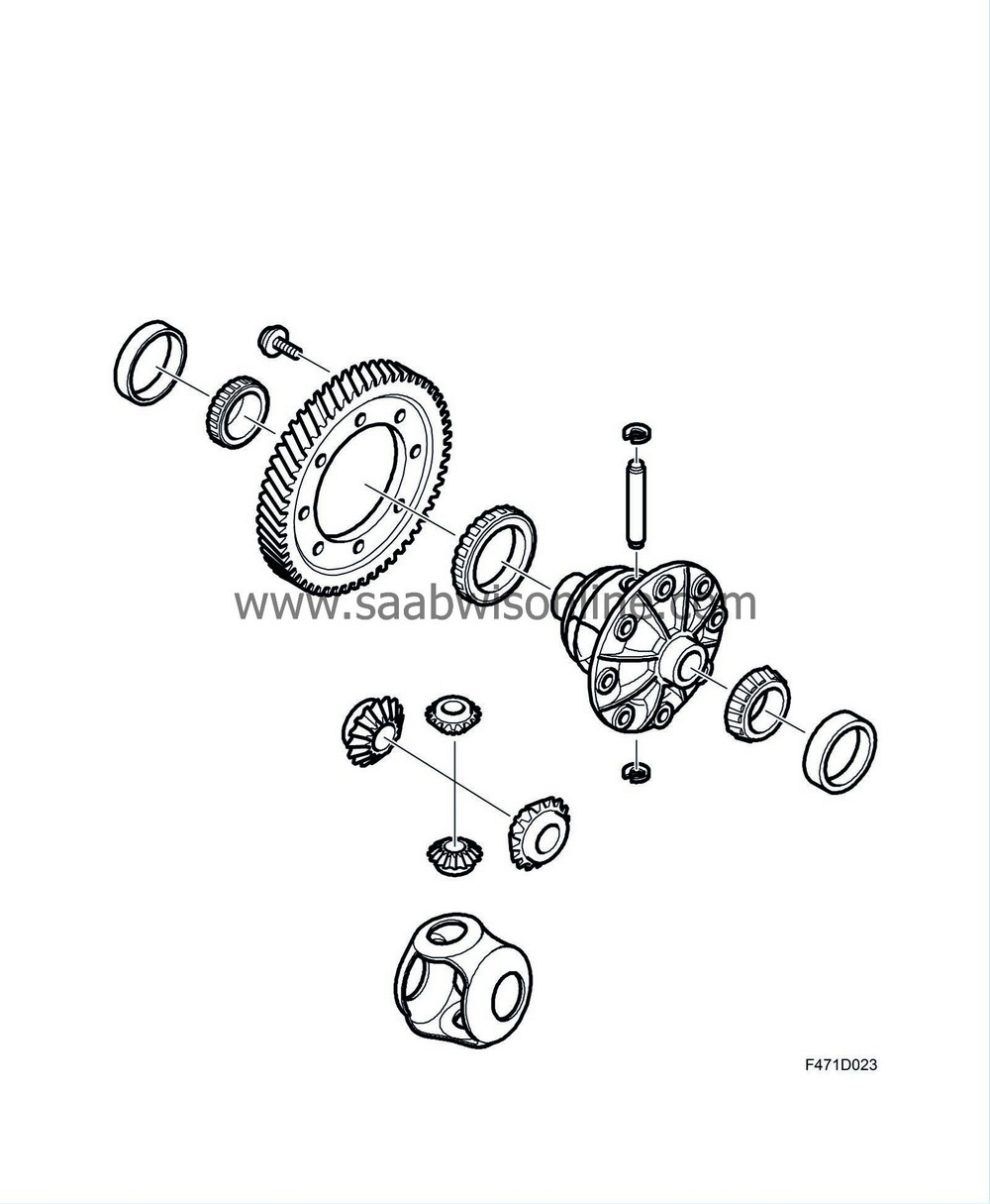
Differential
The function of the differential is to allow the wheel of the car to rotate faster than the inner wheel when cornering. The small differential pinions then rotate around the differential pinion shaft when the larger differential pinions rotate at different speeds and are stationary whilst driving straight ahead when the larger differential pinions rotate at the same speed.Power is transferred from the final drive pinion to the final drive gear which is mounted on the differential housing. From the housing the power is transmitted via the small pinions to the large ones which are attached to inner carriers and intermediate shaft with splined joints. Thence the power is transmitted through the drive shafts to the wheels.

