Power unit, to remove, B207
|
|
Power unit, to remove, B207
|
 Warning
|
|
There is a large number of cables, hoses, wires, etc., that are secured with hard plastic cable ties. After tightening, the loose ends of these cable ties are cut off and may leave more or less sharp edges at fixing points.
|
|
Pay attention to the risk of cuts caused by these sharp ends!
|
|
|
|
|
|
|
1.
|
Place the car on a lift and apply wing covers.
|
|
2.
|
Open the cap on the expansion tank.
|
|
3.
|
Raise the car slightly and remove the front wheels.
|
|
4.
|
Remove the lower spoiler shield. Detach the hose from the headlight washer and unplug and remove the connector.

|
|
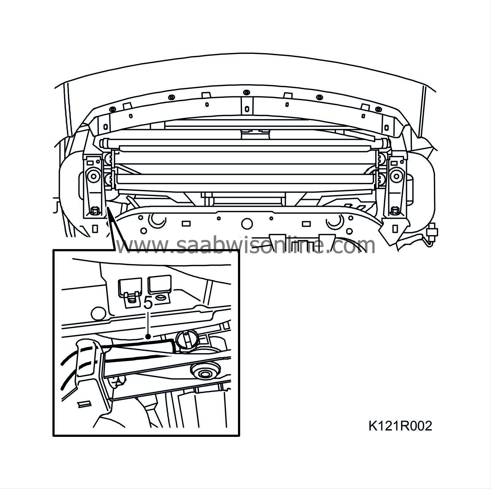
5.
|
Place a receptacle under the car. Connect a hose to the radiator and drain the coolant. Remove the hose and close the cock.
|
|
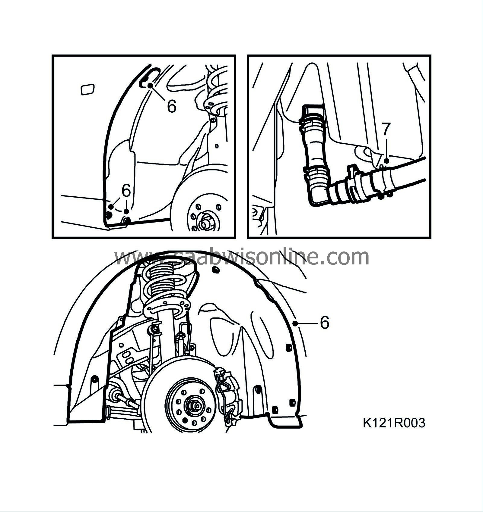
6.
|
Remove the right wing liner and detach the front part of the left wing liner so that the subframe is free.
|
|
7.
|
Detach the headlight washer hose and plug the washer fluid reservoir.
|
|
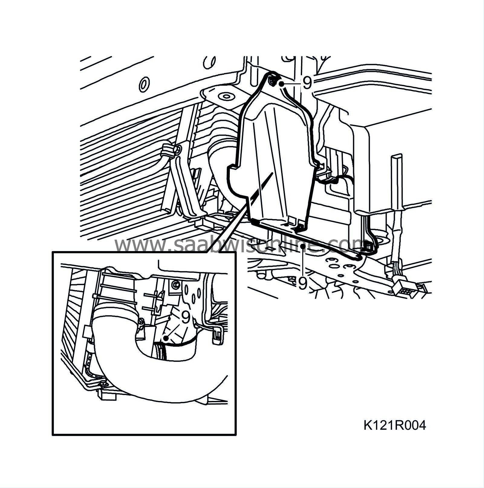
9.
|
Remove the cover on the left side and detach the coolant hose from the radiator.
|
|
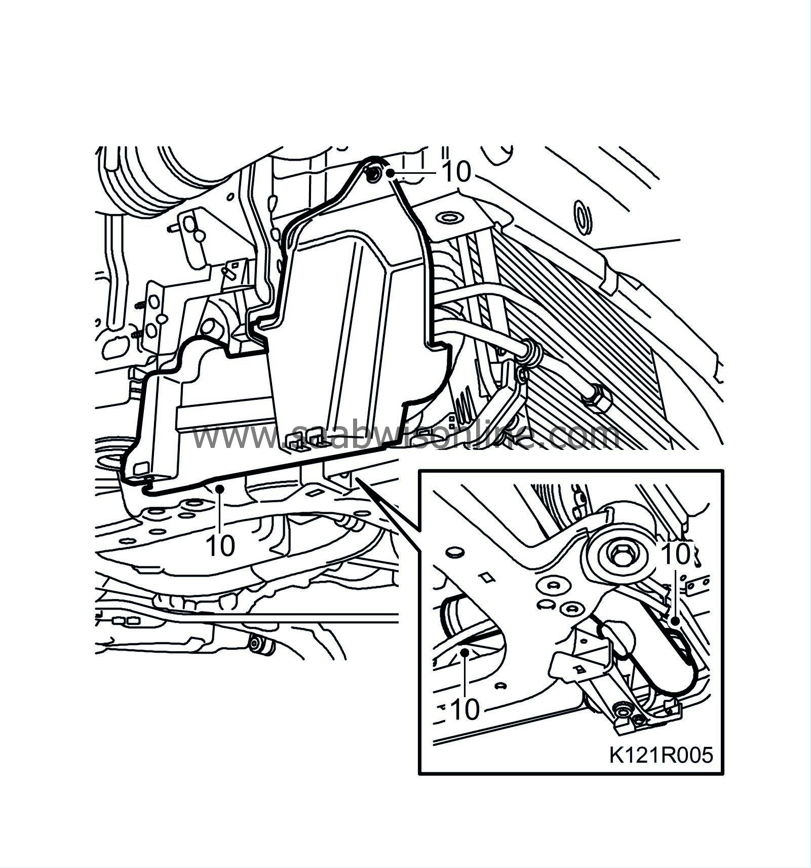
10.
|
Remove the cover on the right-hand side and the hose between the charge air cooler and the charge air pipe.
|
|
11.
|
Lower the car and remove the upper engine cover and the dipstick.

|
|
12.
|
Remove the battery cover.
|
|
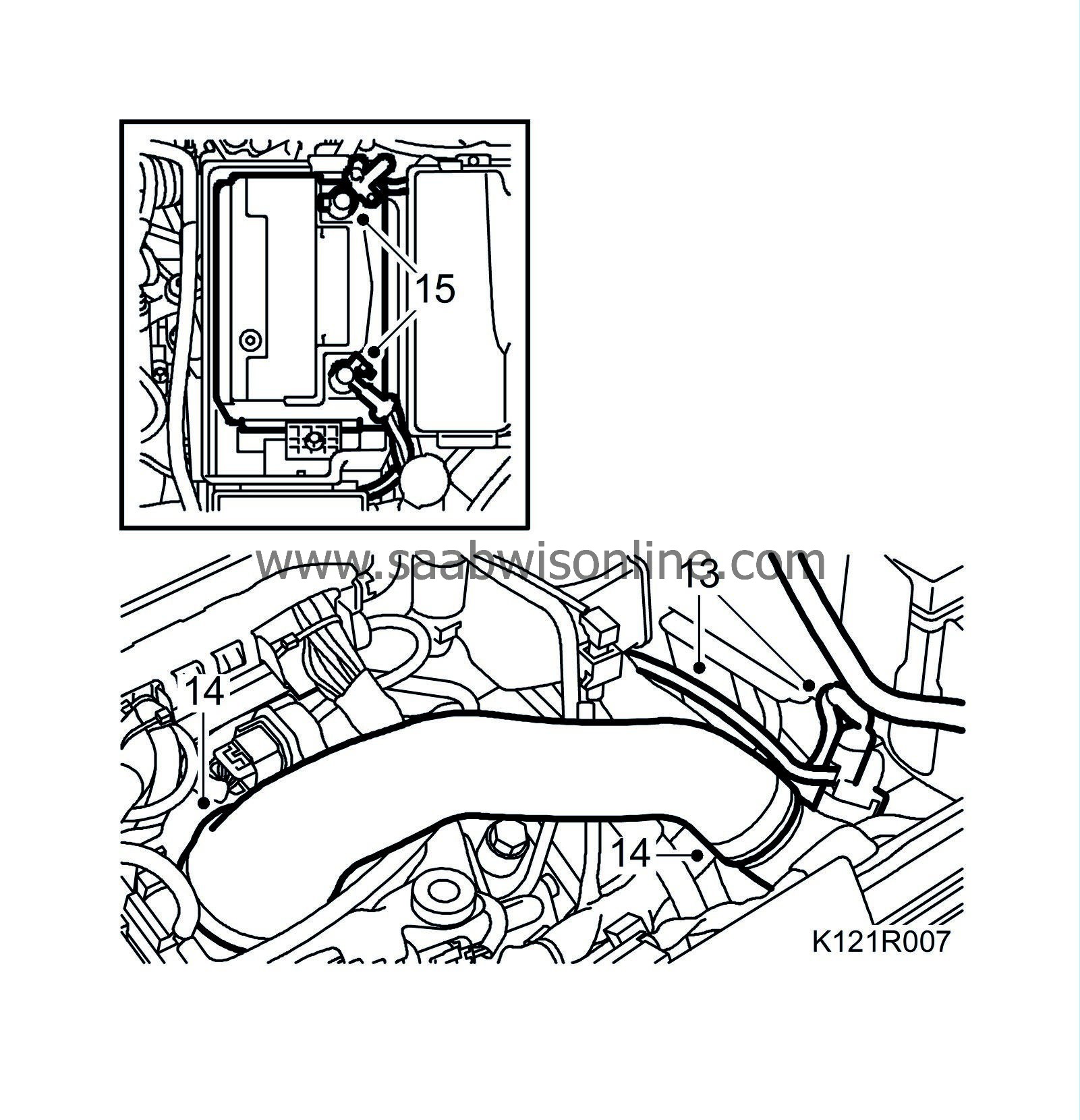
13.
|
Unplug the connector to the pressure/temperature sensor and disconnect the charge air bypass valve hose.
|
|
14.
|
Detach the charge air hose from the throttle body and the charge air pipe.
|
|
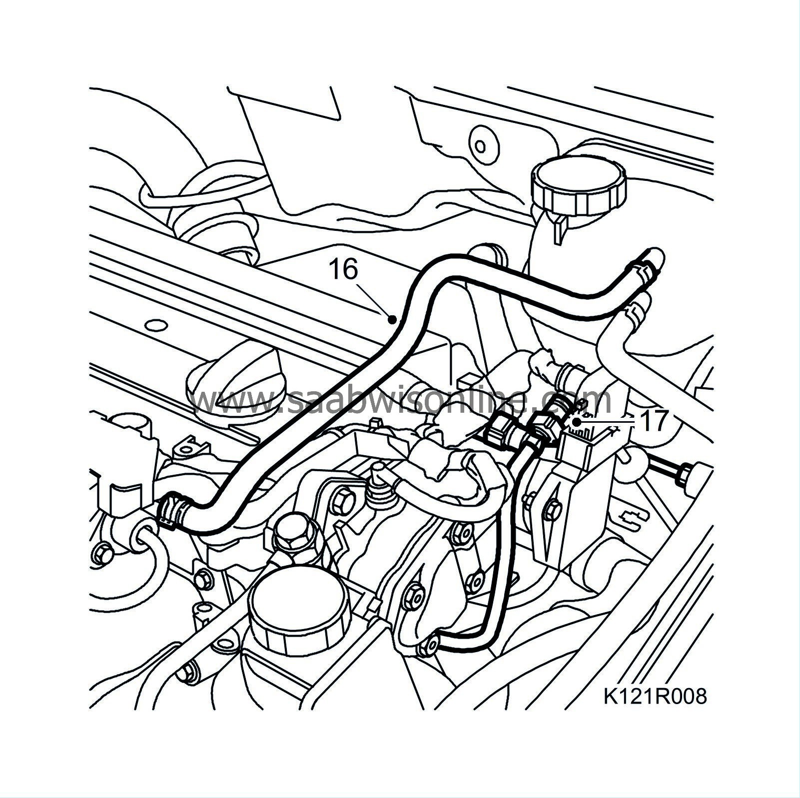
16.
|
Detach the bleeder hose from the engine.
|
|
17.
|
Detach the vacuum hose quick-release coupling from the vacuum pump.
|
|
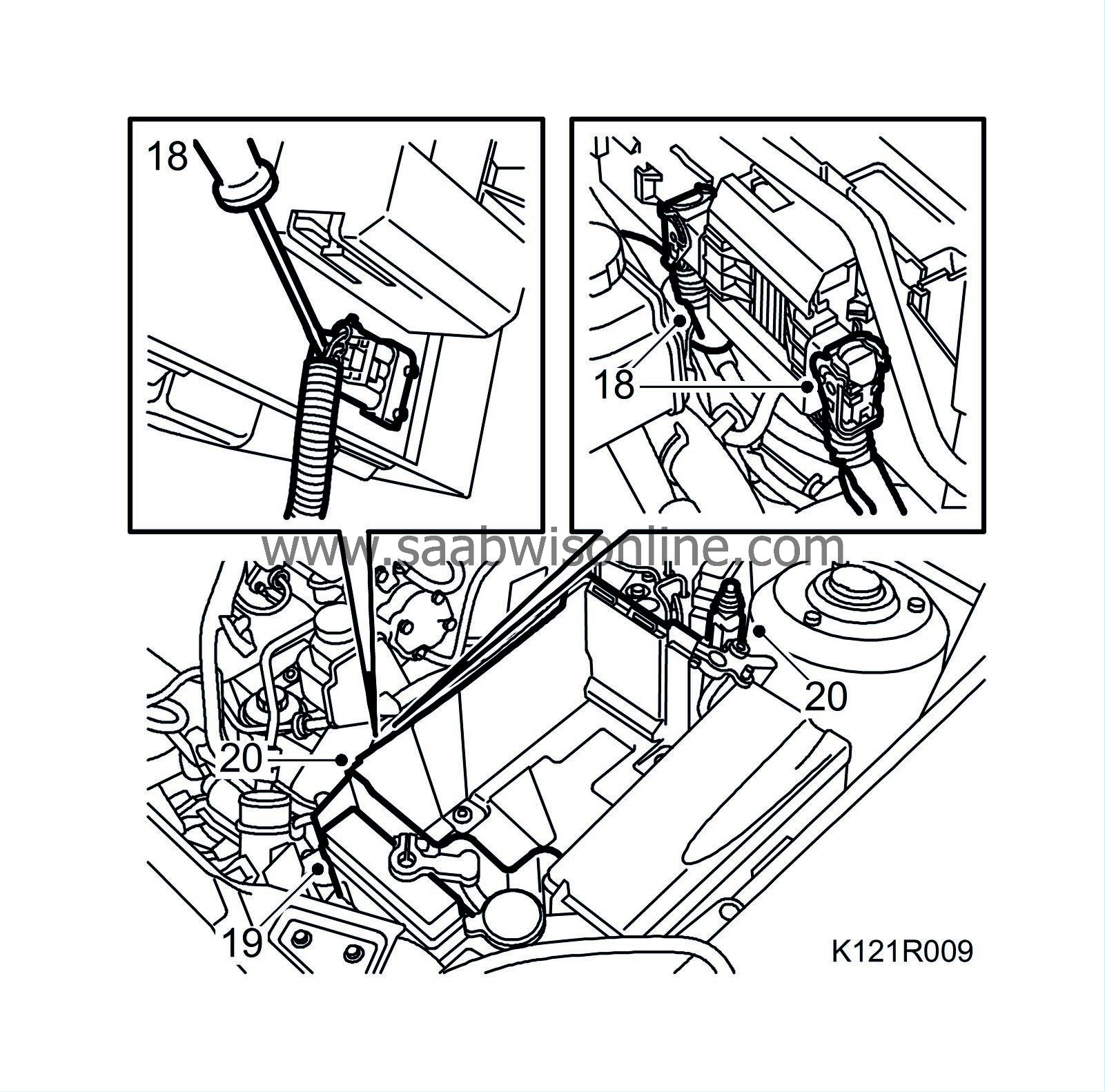
18.
|
Aut:
Unplug the connector to the TCM. Remove the cover with the control module. Unplug the connector under the control module.
|
|
19.
|
Undo the electrical centre in front of the battery tray and move it aside.
|
|
20.
|
Unplug the bonnet switch connector, undo the cable clip and remove the battery tray.
|
|
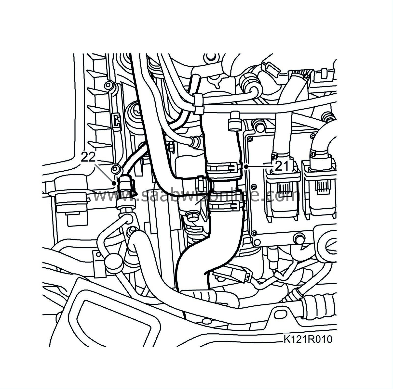
21.
|
Remove the upper radiator hose.
|
|
22.
|
Unplug the connector for the A/C pressure sensor.
|
|
23.
|
Remove the mass air flow sensor connector.

|
|
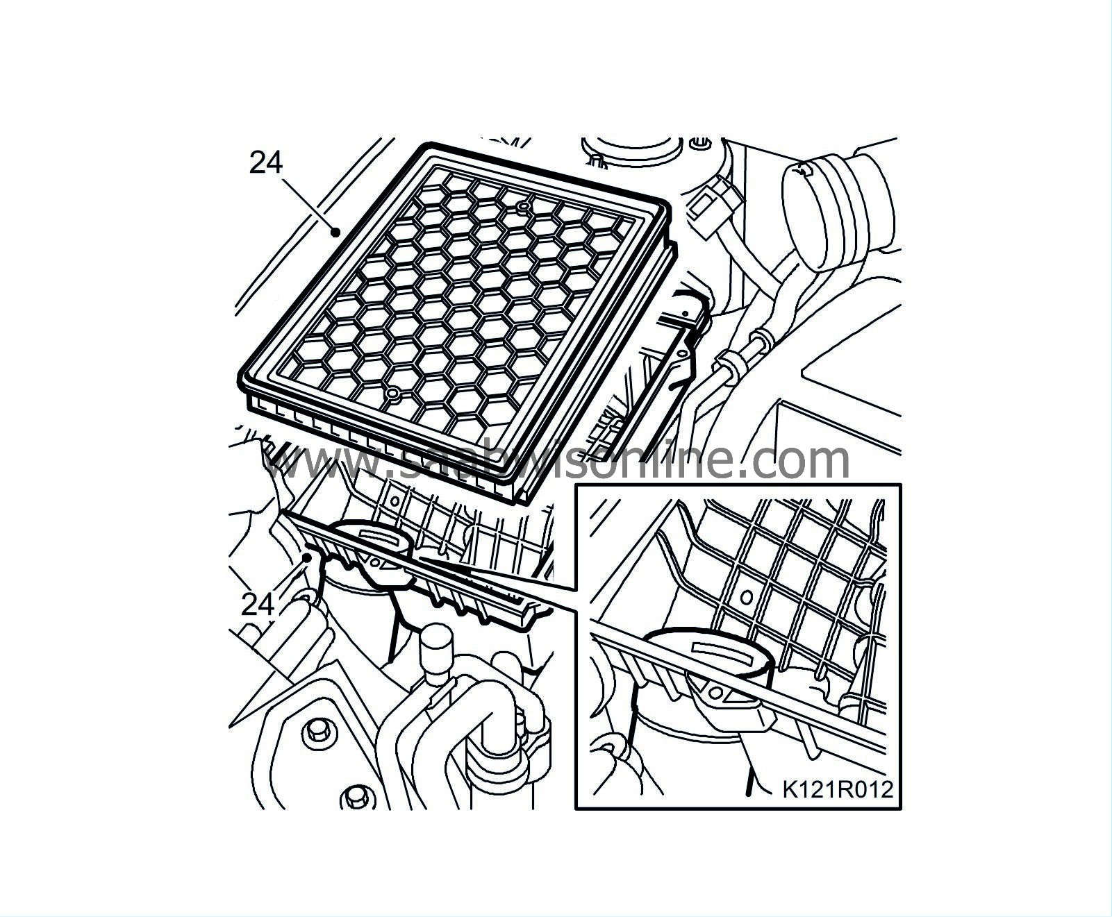
24.
|
Remove the air cleaner cover and the air cleaner. Detach the inlet hose and remove the air cleaner casing.
|
|
26.
|
Remove the cover on the electrical centre and undo the two retaining bolts.
|
|
27.
|
Disconnect the positive cable from the battery.
|
|
28.
|
Undo the retaining bolt on the engine harness connector in the electrical centre.
|
|
29.
|
Remove the engine harness clamp from the body.
|
|
30.
|
Bend up the engine harness and secure it to the engine with e.g. one
83 95 212 Strap
.
|
|
31.
|
Remove the coolant hose from the thermostat housing.

|
|
32.
|
Undo the coolant hose quick-release couplings while trapping any coolant spill, bend aside and secure the hoses to the engine.
|
|
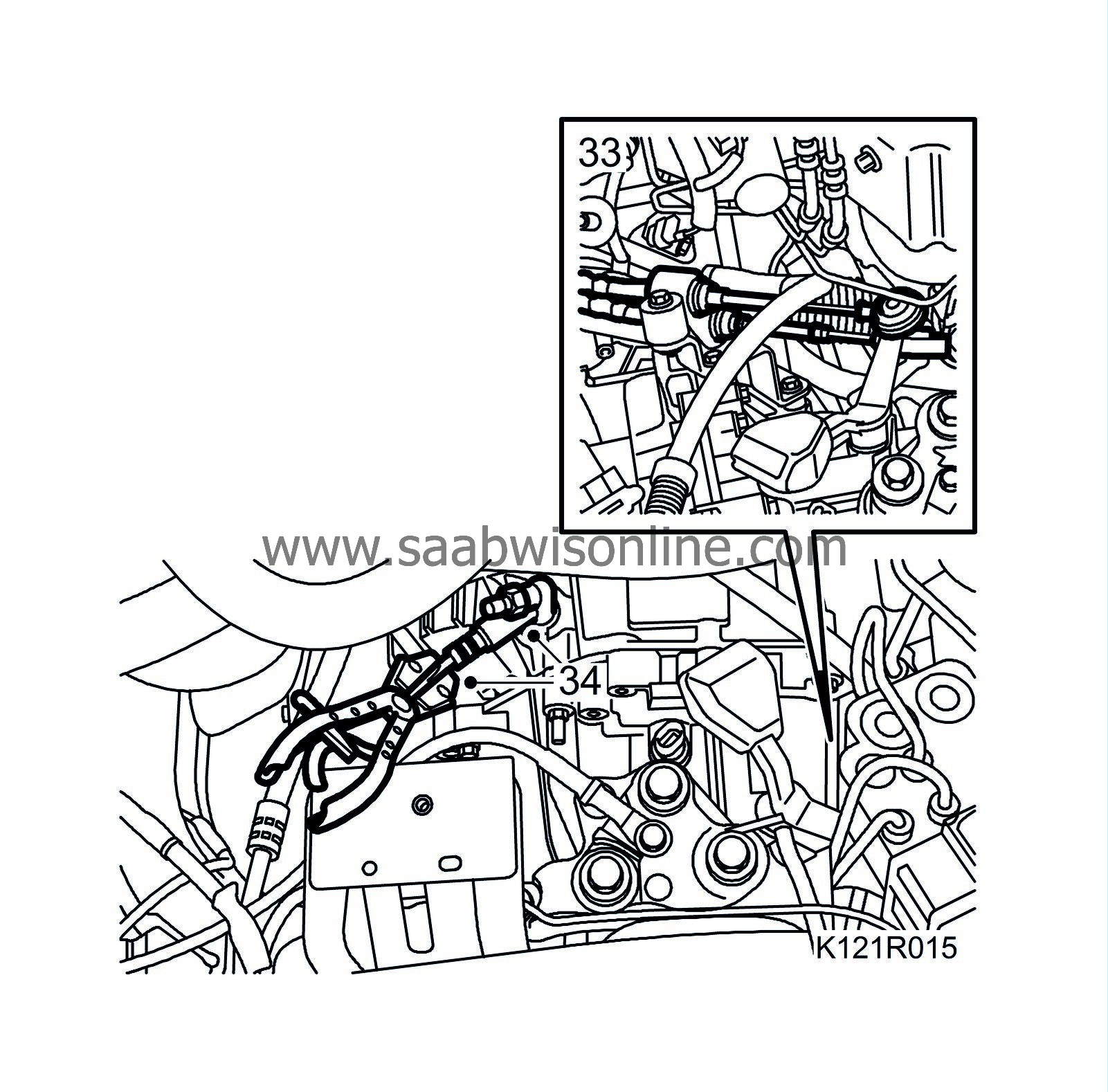
33.
|
Detach the gear cables from the gearbox. Carefully move them aside.
|
|
34.
|
Man:
Fit
30 07 739 Hose pinch-off pliers
to the clutch hose and disconnect the quick coupling from the clutch slave cylinder.
|
Warning
|
|
The work involved in removing the fuel pipe requires working with the vehicle's fuel system. The following points should therefore be heeded in conjunction with these measures:
|
|
• Have a class BE fire extinguisher on hand! Be aware of the risk of sparks, i.e. in connection with electric circuits, short-circuiting, etc.
|
|
• Absolutely No Smoking!
|
|
• Ensure good ventilation! If there is approved ventilation for evacuating fuel fumes then this must be used.
|
|
• Wear protective gloves! Prolonged exposure of the hands to fuel can cause irritation to the skin.
|
|
• Wear protective goggles.
|
|
|
|
|
|
|
|
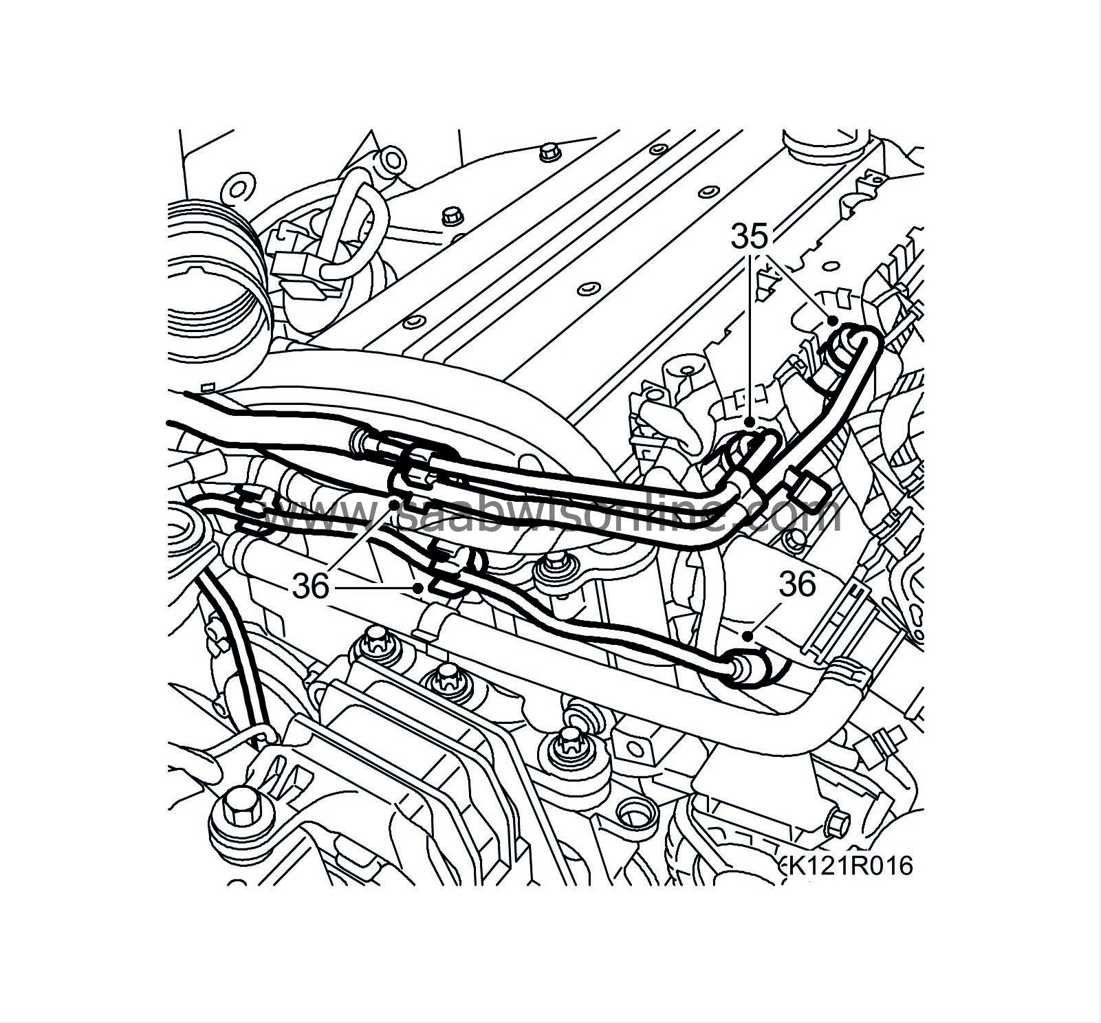
35.
|
Release any pressure in the fuel system by carefully pressing the service valve needle. Collect any fuel spill. Detach both fuel lines from the fuel rail while gripping the lower nut. Plug the fuel lines. Use
82 92 948 Plugs, A/C system assy
.
|
|
36.
|
Disconnect the quick-release coupling for the breather line and detach the fuel lines and bleeder lines from the clips on the camshaft cover. Bend up the breather hose from the intake manifold and place it on the camshaft cover.
|
|
37.
|
Check and adjust the steering wheel and the steering assembly so that they are pointing straight ahead.
|
Warning
|
|
In order to avoid the contact roller for the airbag twisting and breaking the steering wheel must be secured via the steering column lock or by taping it to the panel.
|
|
|
|
|
|
|
|
38.
|
Raise the car and detach the steering shaft from the steering gear.

|
|
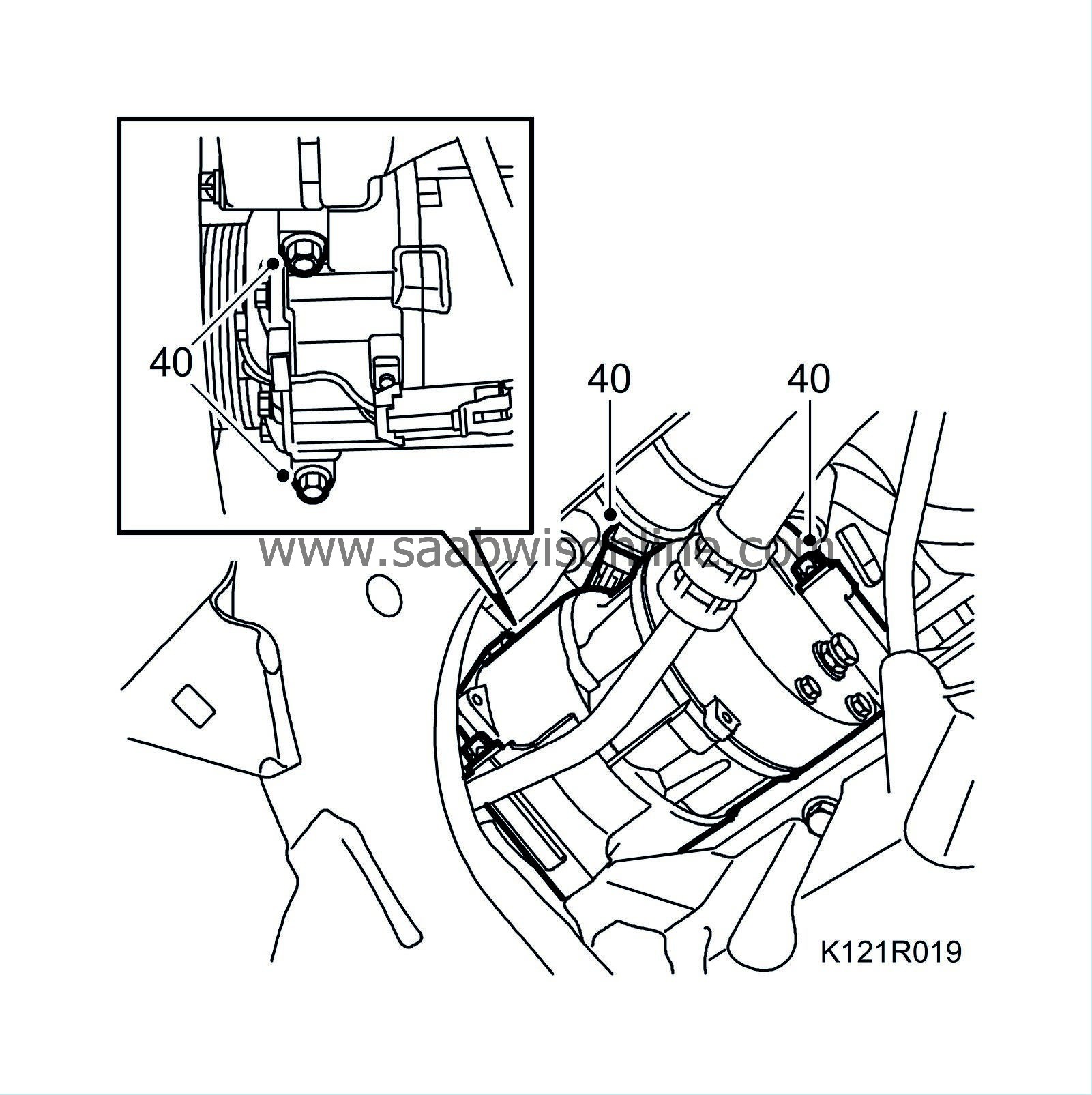
40.
|
Unplug the A/C compressor connector and remove the A/C compressor retaining bolts.
|
|
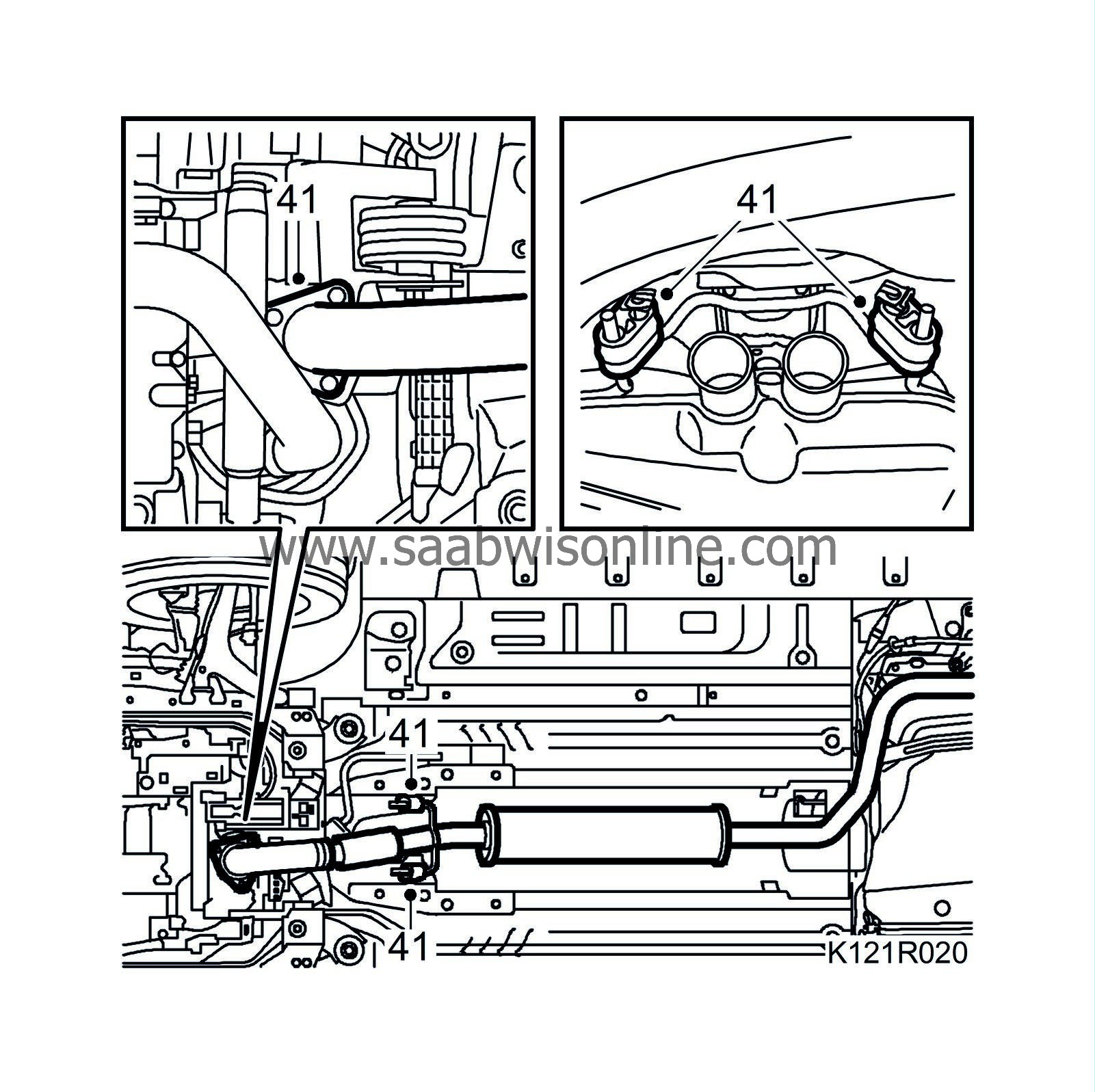
41.
|
Remove the nuts and rubber mountings. Lower the exhaust system assembly.
|
|
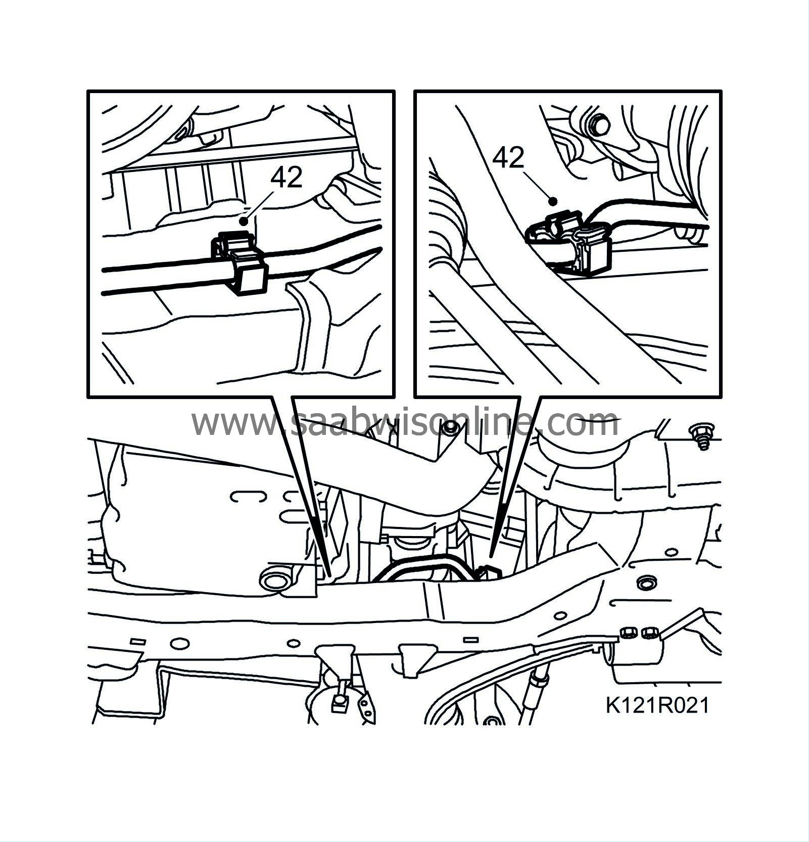
42.
|
Release the clips holding the power steering pipe to the subframe.
|
|
43.
|
Fit the centring tool, engine and subframe, see
Centring tool, engine and subframe
. Adjust the tool approx. 10 mm so that the engine mountings are unloaded slightly.
|
|
45.
|
Attach two
83 95 212 Straps
to the radiator member, lower the strap and wind it an extra turn round the A/C compressor to relieve it.
|
|
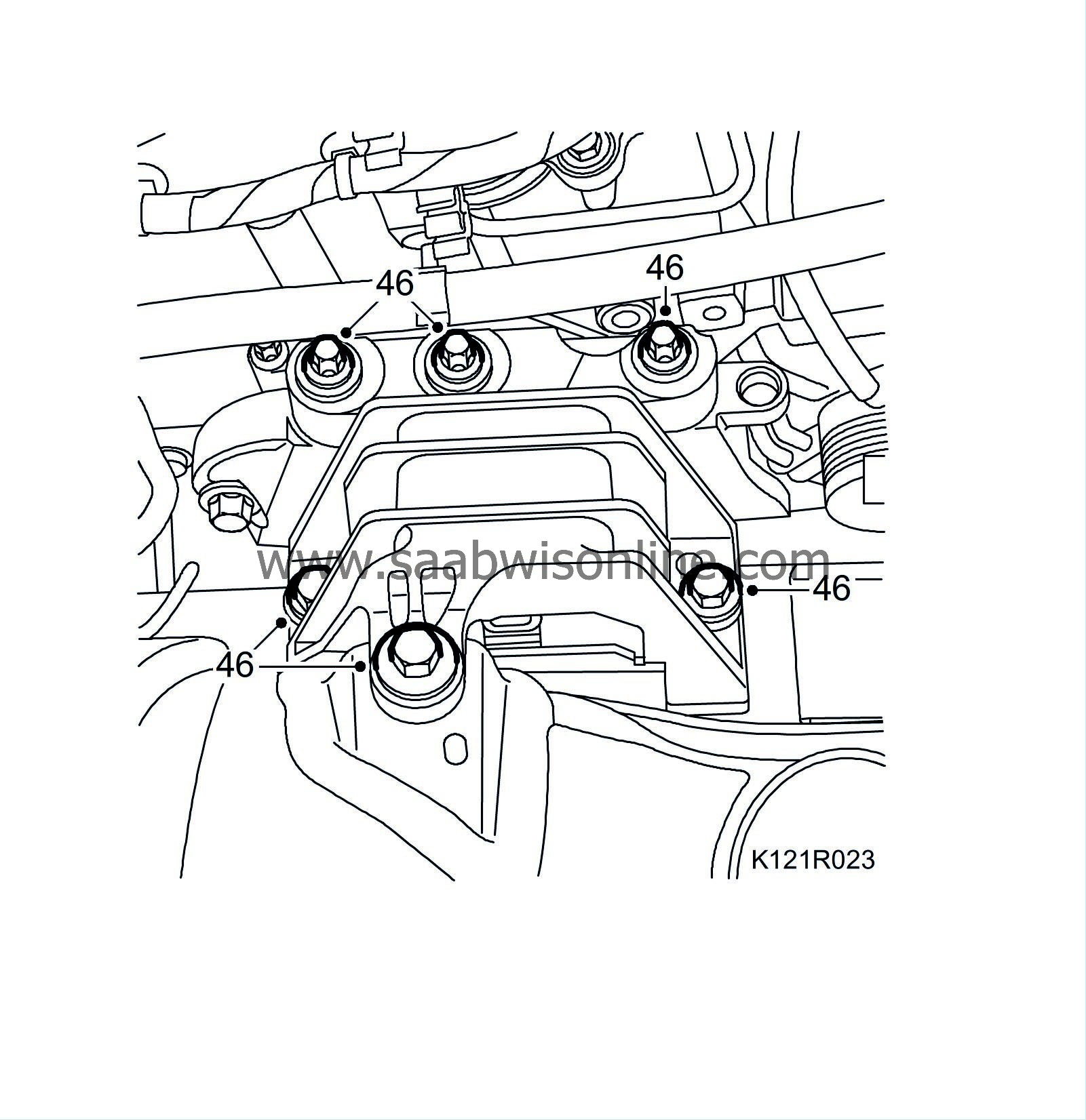
46.
|
Remove the right engine mounting
|
|
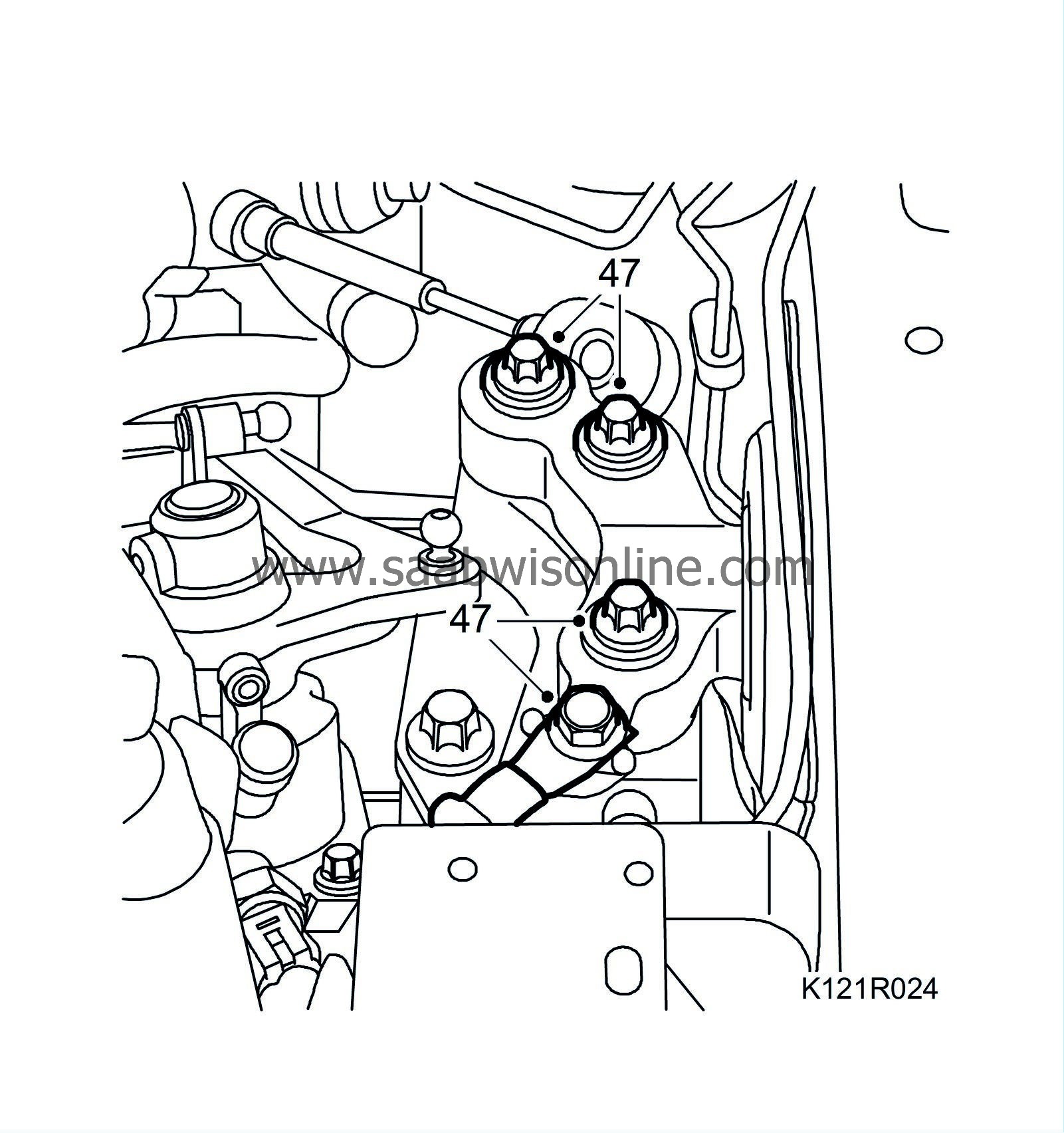
47.
|
Remove the left engine mounting.
|
|
48.
|
Raise the car and undo the drive shaft centre nuts. Detach the drive shafts from the hub. Use
89 96 951 Drive shaft hub puller
or a brass drift and mallet.
|
Warning
|
|
Use protective goggles to protect against flying splinters of metal.
|
|
|
|
|
|
|
|
50.
|
Undo the anti-roll bar's lower links while gripping the flats with a thin spanner.
|
|
51.
|
Undo the lower swivel joints from the steering swivel members and lower the suspension arms.
|
|
52.
|
Undo the drive shafts and move them away.
|
|
53.
|
Unplug the angle sensor connector (option).
|
|
55.
|
Position the trolley lift, raise and guide the locating pins into the subframe reference holes. Adjust the lifting columns with height adjusters
83 95 170 Adapter
so that they make even contact with the subframe. Use the body locating pins to check that the subframe is correctly positioned in relation to the body. See
Centring tool, engine and subframe
.
|
|
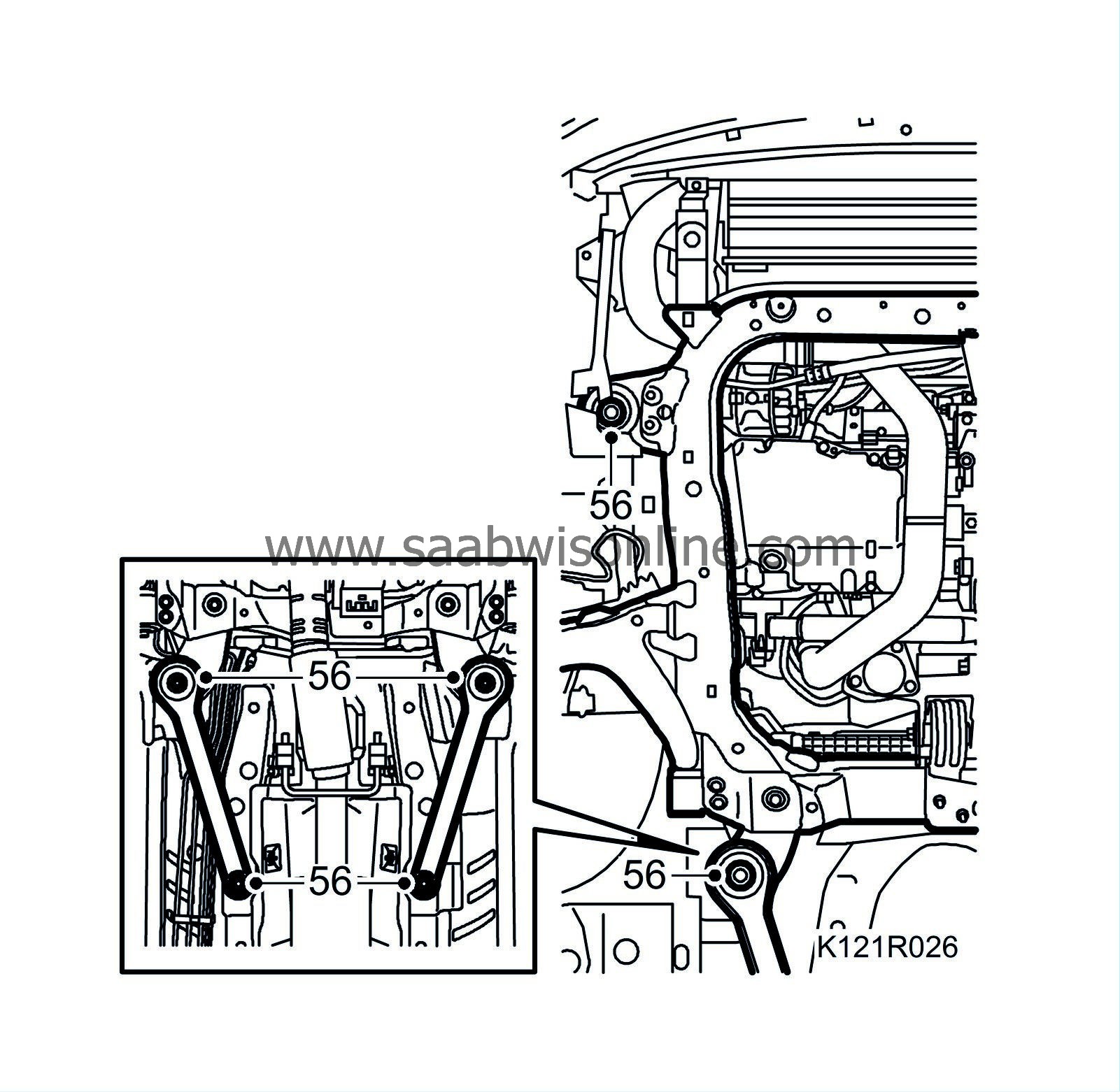
56.
|
Raise the trolley lift slightly for stable contact and undo the subframe bolts in the body.
|
|
57.
|
Carefully lower the power unit on the trolley lift, making sure nothing gets caught or damaged.
|


