PRE-RELEASE
Spare part cylinder block, removing, B207, 4WD
| Spare part cylinder block, removing, B207, 4WD |
| To remove |
| 1. |
Place the car on a lift.
|
|
| 2. |
Place a receptacle under the car. Wear protective gloves. Remove the plug (A) and drain the gearbox oil. Fit the plug.
Tightening torque, automatic transmission 45 Nm (33 lbf ft) Tightening torque, manual gearbox 50 Nm (37 lbf ft)
|
|||||||||||||||||
| 3. |
Remove the drain plug (A) and drain the engine oil. Fit the plug with a new O-ring.
Tightening torque 25 Nm (18 lbf ft) 
|
|
| 4. |
Remove the engine assembly, see
Power unit removal, 4WD
.
|
|
| 5. |
Leave the power train on the trolley lift.
|
|
| 6. |
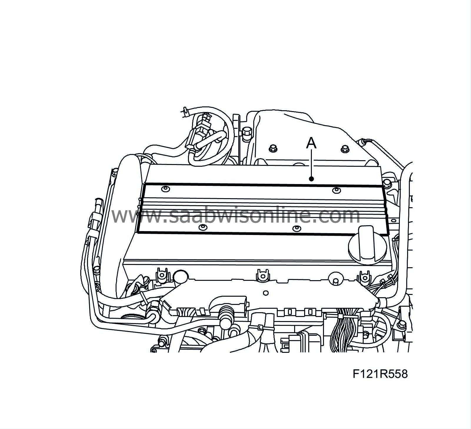
Remove the cover (A) over the spark plugs.
|
||||||||||
| 7. |
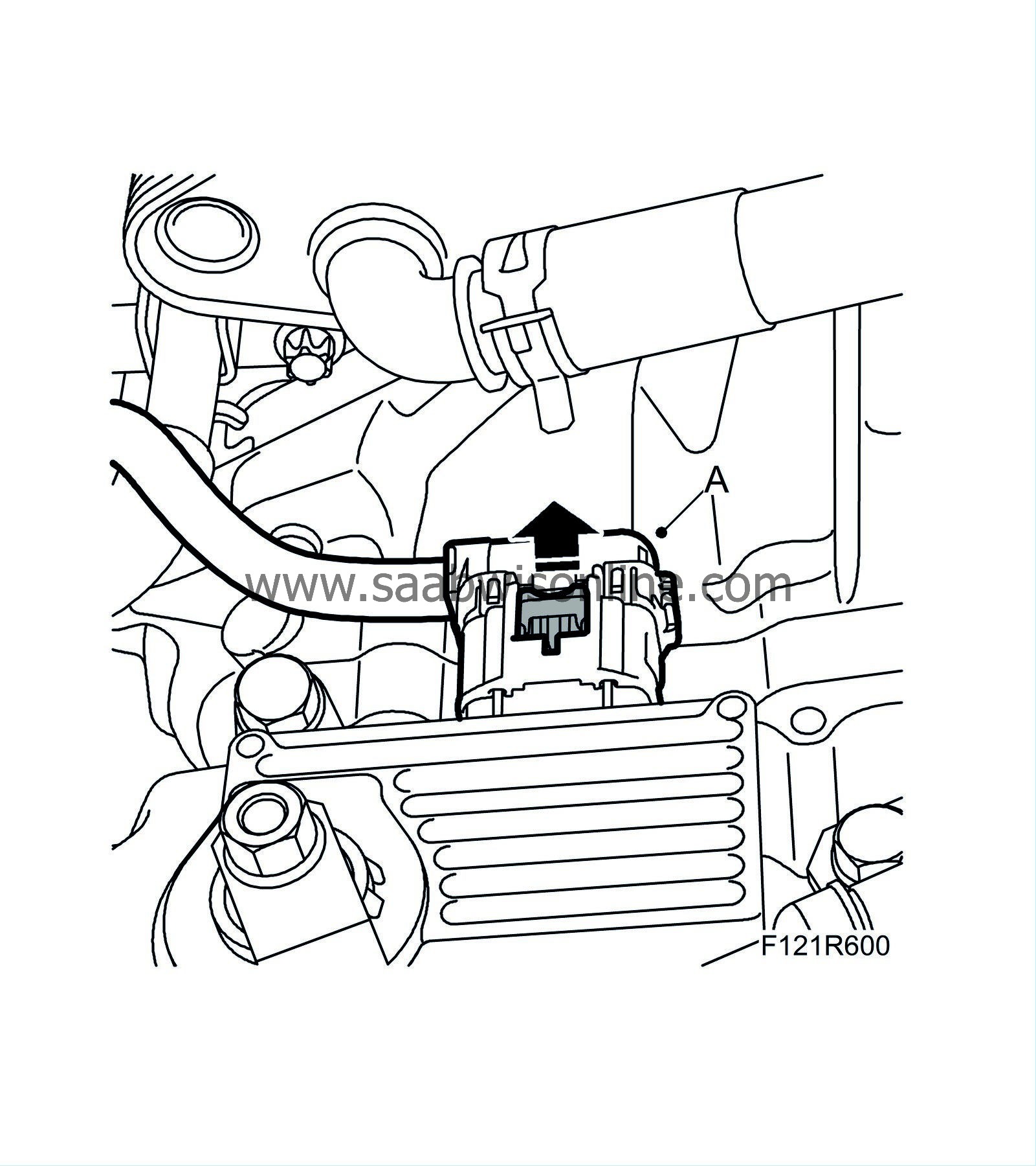
Unplug the control module connector. (A)
|
|
| 8. |
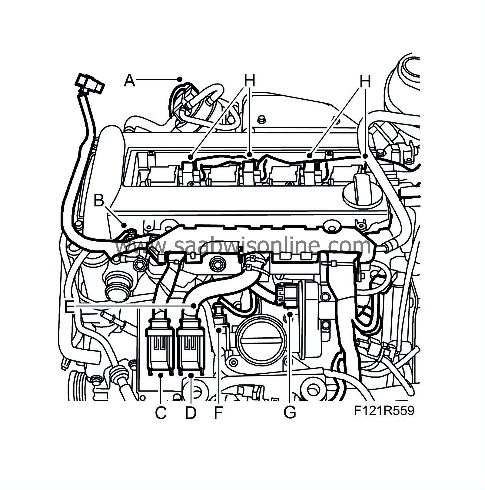
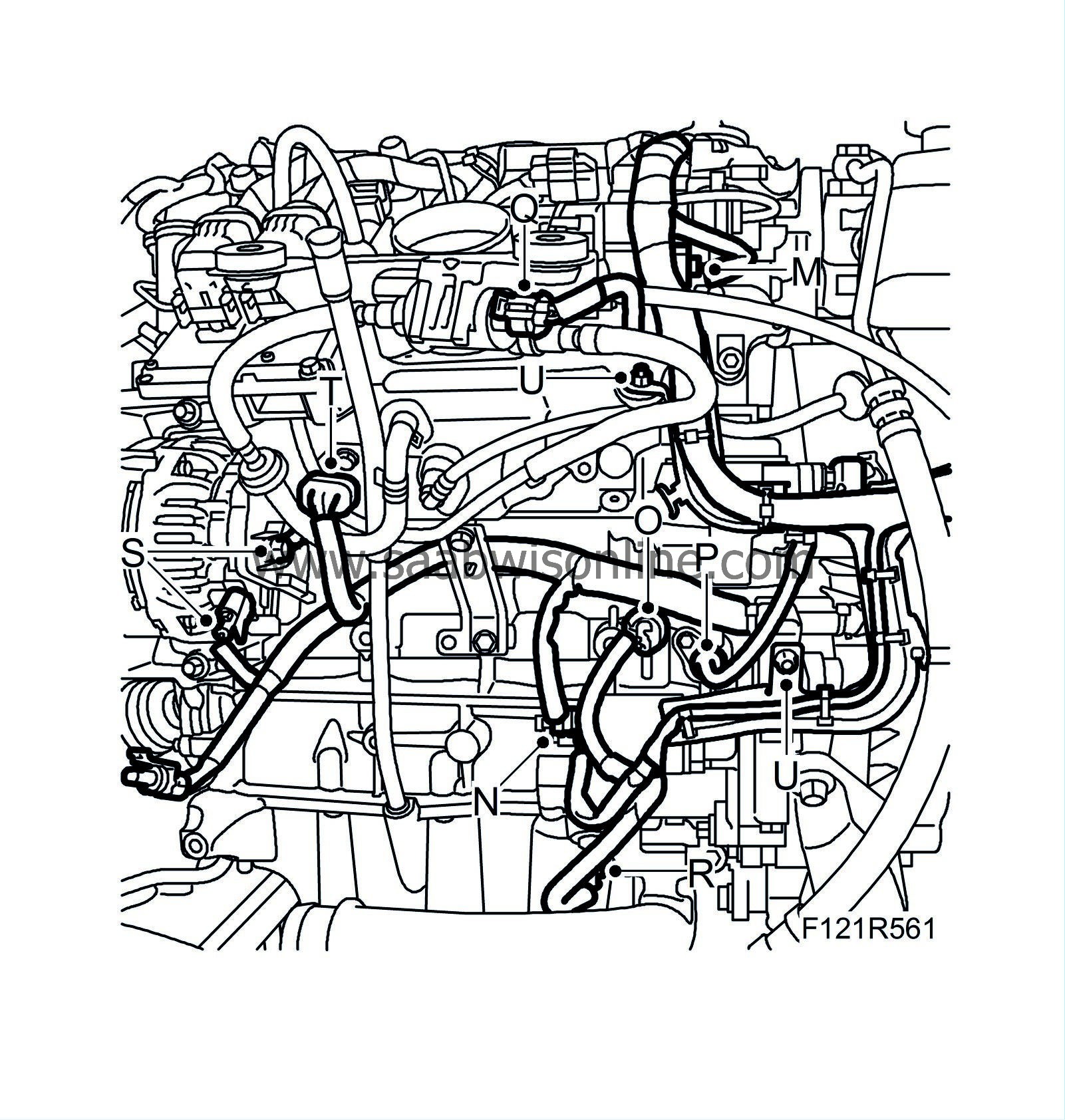
Remove the engine wiring harness using the following method:
|
|
| • |
Unplug the connector from the charge air solenoid valve (A).
|
| • |
Unplug the connector from the coolant temperature sensor (B).
|
| • |
Unplug the engine control module connector (C).
|
| • |
Unplug the engine control module connector (D).
|
| • |
Detach grounding point G7 (E).
|
| • |
Unplug the bypass valve connector (F).
|
| • |
Unplug the throttle body connector (G).
|
| • |
Unplug the 4 ignition coil connectors (H).
|
| • |
Unplug the connector from the ionization detection module (I).

|
| • |
Unplug the front heated oxygen sensor connector (J).
|
| • |
Unplug the rear heated oxygen sensor connector (K).
|
| • |
Unplug the connector of the servo pump pressure sensor (L).
|
| • |
Unplug the connector from the intake manifold pressure sensor (M).
|
| • |
Detach the starter motor switches (N).
|
| • |
Detach the oil pressure switch (O).
|
| • |
Unplug the crankshaft position sensor connector (P).
|
| • |
Unplug the EVAP canister purge valve connector (Q).
|
| • |
Unplug the oil level sensor connector (R).
|
| • |
Unplug the alternator connector (S).
|
| • |
Detach connector H8-9 (T).
|
| • |
Remove the wiring harness retaining bolts. Pull out the wiring harness and lift it aside (U).
|
| 9. |
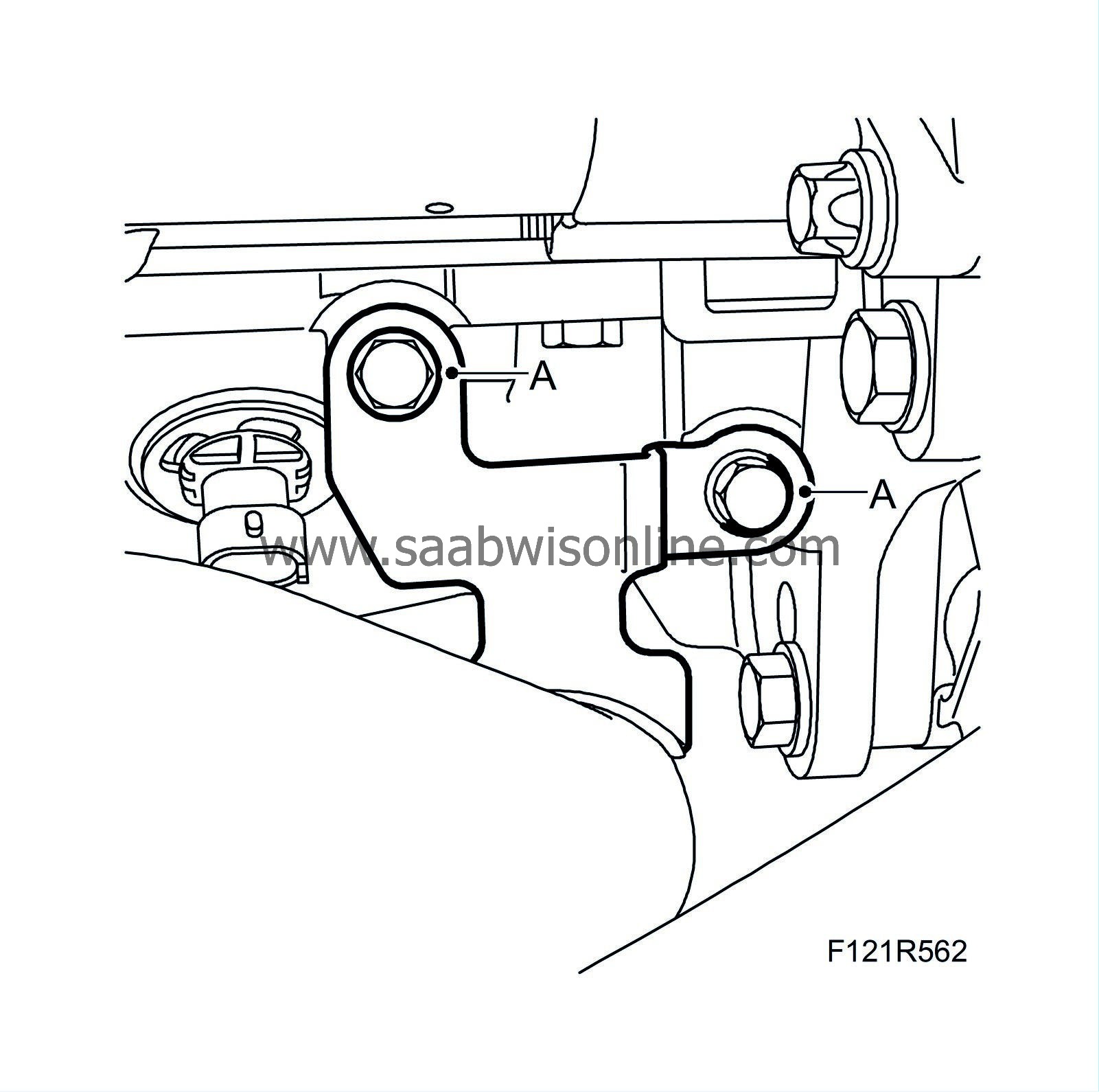
Remove the bolts (A) securing the lower charge air pipe.
|
|
| 10. |
Remove the heat shield (A) and charge air pipe (B).

|
|
| 11. |
Remove the turbocharger heat shield (A).

|
|
| 12. |
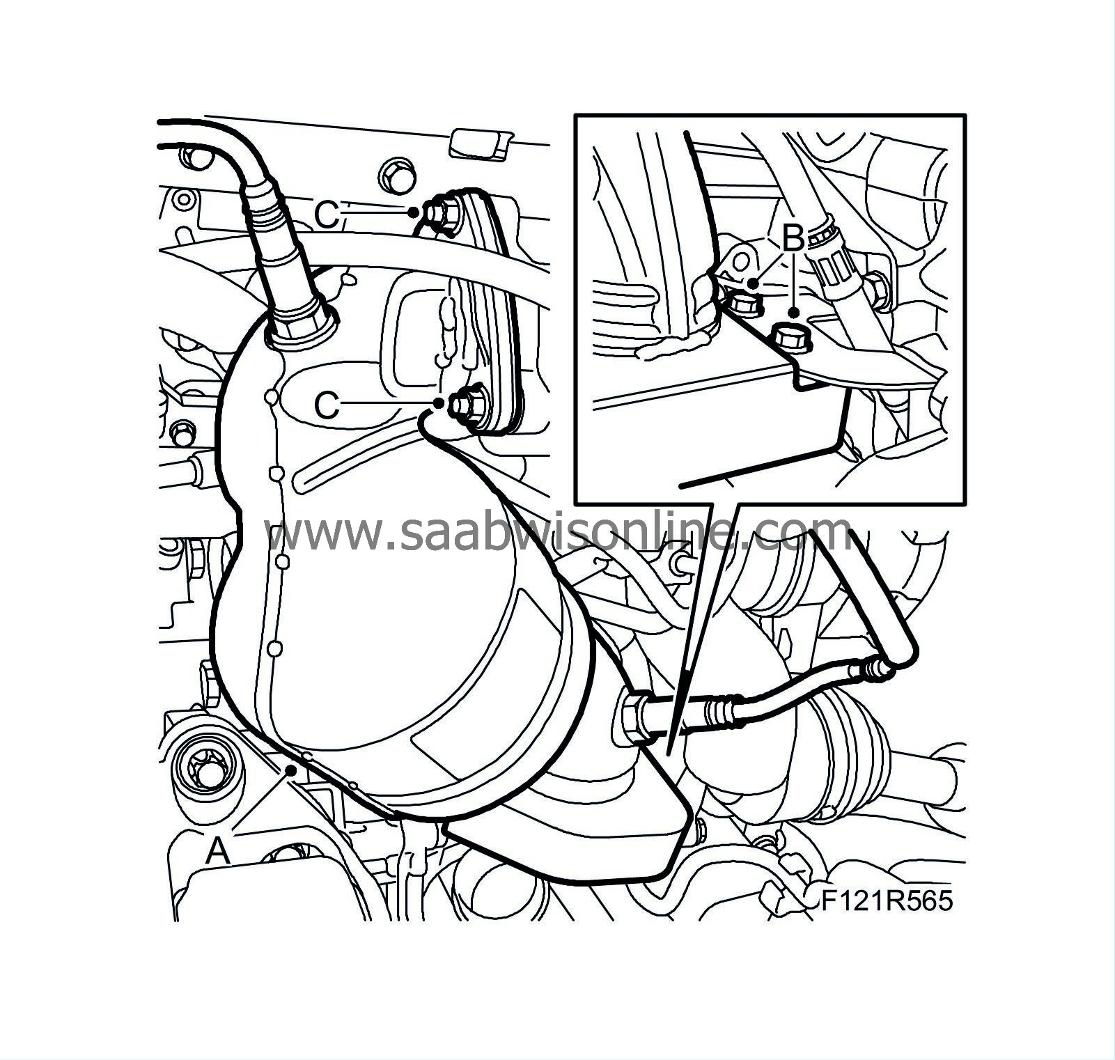
Unplug the heated oxygen sensor connectors and lower the cables carefully.
|
|
| 14. |
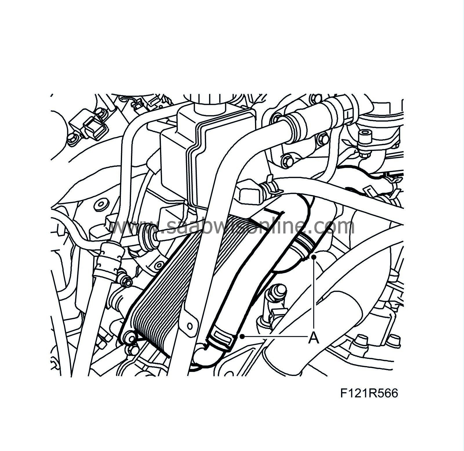
Detach the hoses (A) from the water-cooled oil cooler.
|
|
| 15. |
Remove the turbocharger coolant pipes (A).

|
|
| 16. |
Detach the thermostat housing (B) and pipe (C). Allow the hoses to remain on the thermostat housing.
|
|
| 17. |
RH side
: Tap out the drive shaft from the intermediate shaft with a brass drift and mallet. Lift out the drive shaft.

|
|
| 18. |
Remove the starter motor (A).

|
|
| 19. |
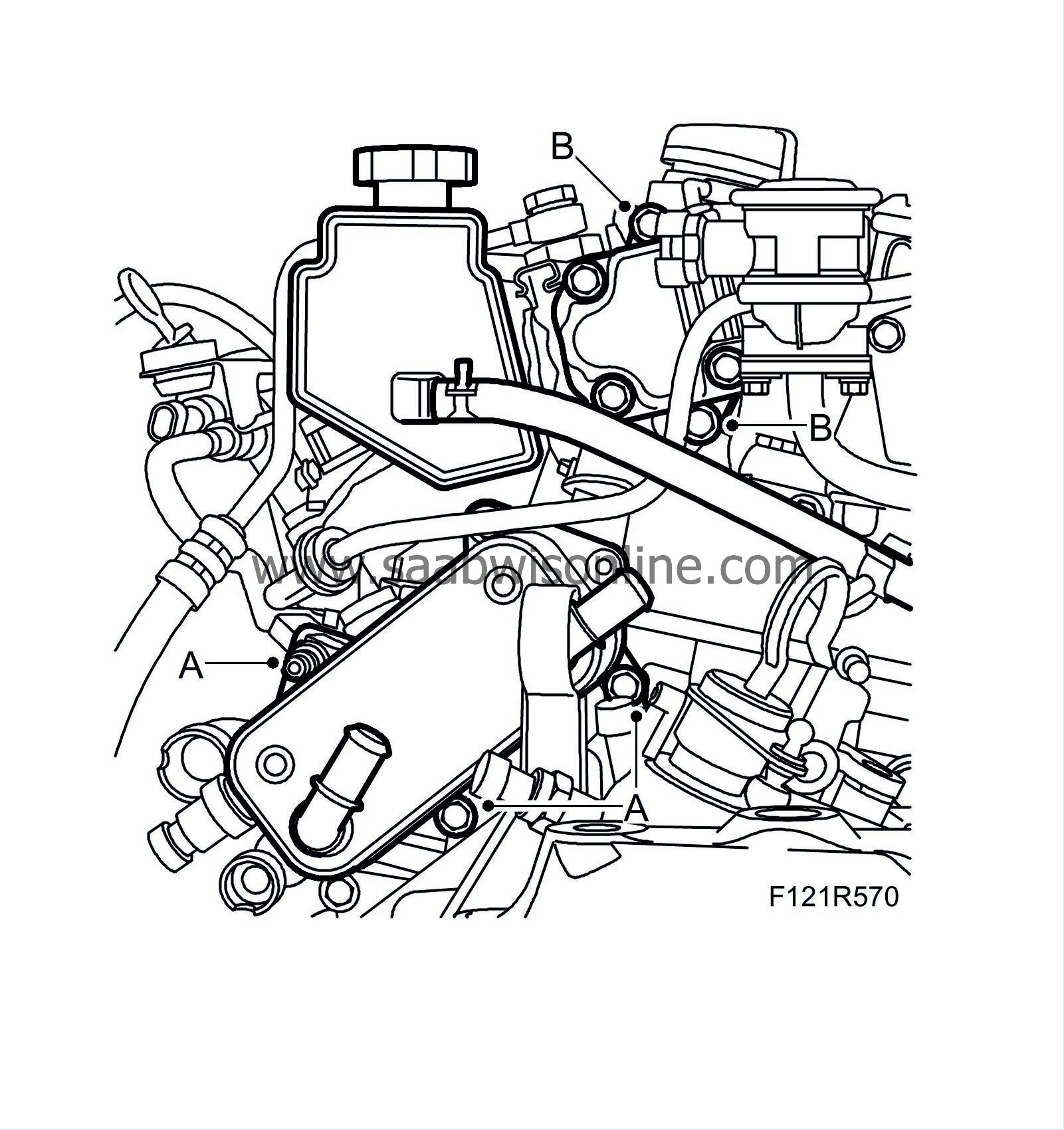
Remove the water-cooled oil cooler (A).
|
|
| 20. |
Remove the power steering pump (B) from the cylinder head and move it aside.
|
|
| 21. |
Aut
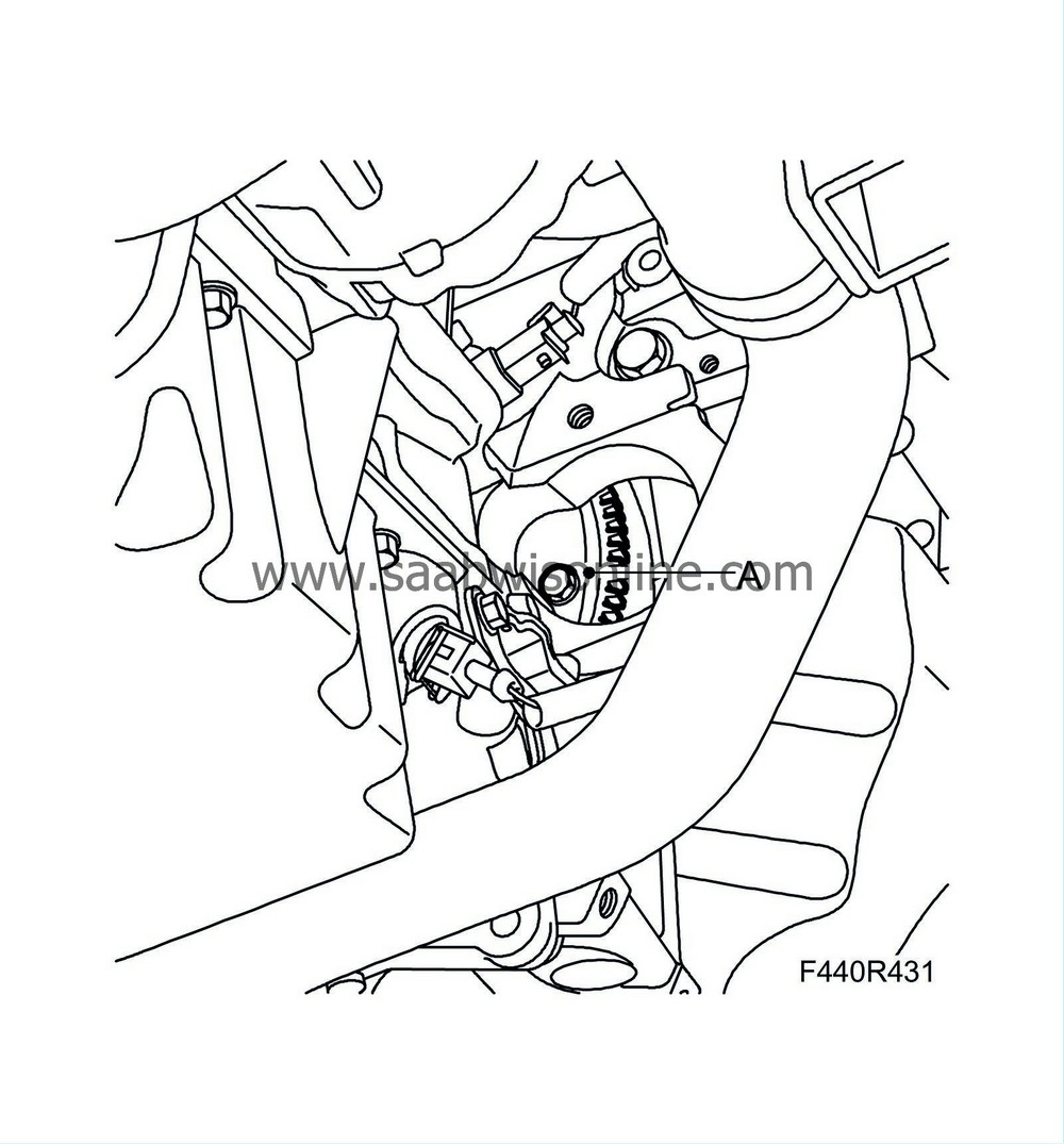
: Remove the 6 bolts (A) securing the torque converter to the driver plate. Rotate the crankshaft clockwise on the pulley centre bolts.
|
|
| 22. |
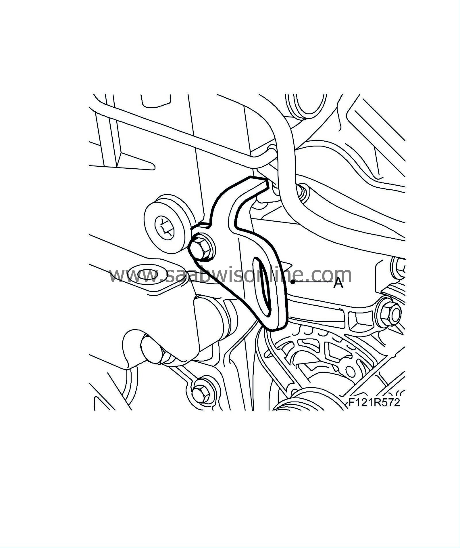
Fit 83 96 178 Lifting eyes, B207 (A).

|
|
| 23. |
Secure the engine with an engine lift.
|
|
| 24. |
Remove the bolts from the front torque arm.
|
|
| 25. |
Remove the bolts from the rear torque arm.
|
|
| 26. |
Raise the engine.
|
|
| 27. |
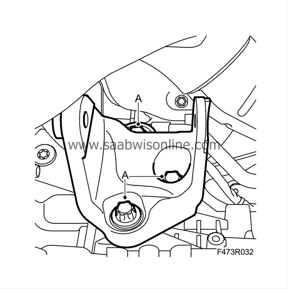
Remove the rear torque arm bracket (A).
|
|
| 28. |
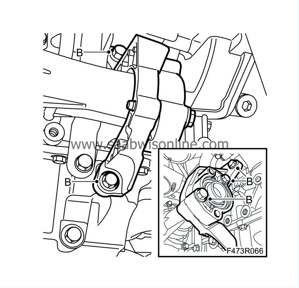
Remove the support bracket (B) from the transfer case.
|
|
| 29. |
Remove the transfer case bolts (C).
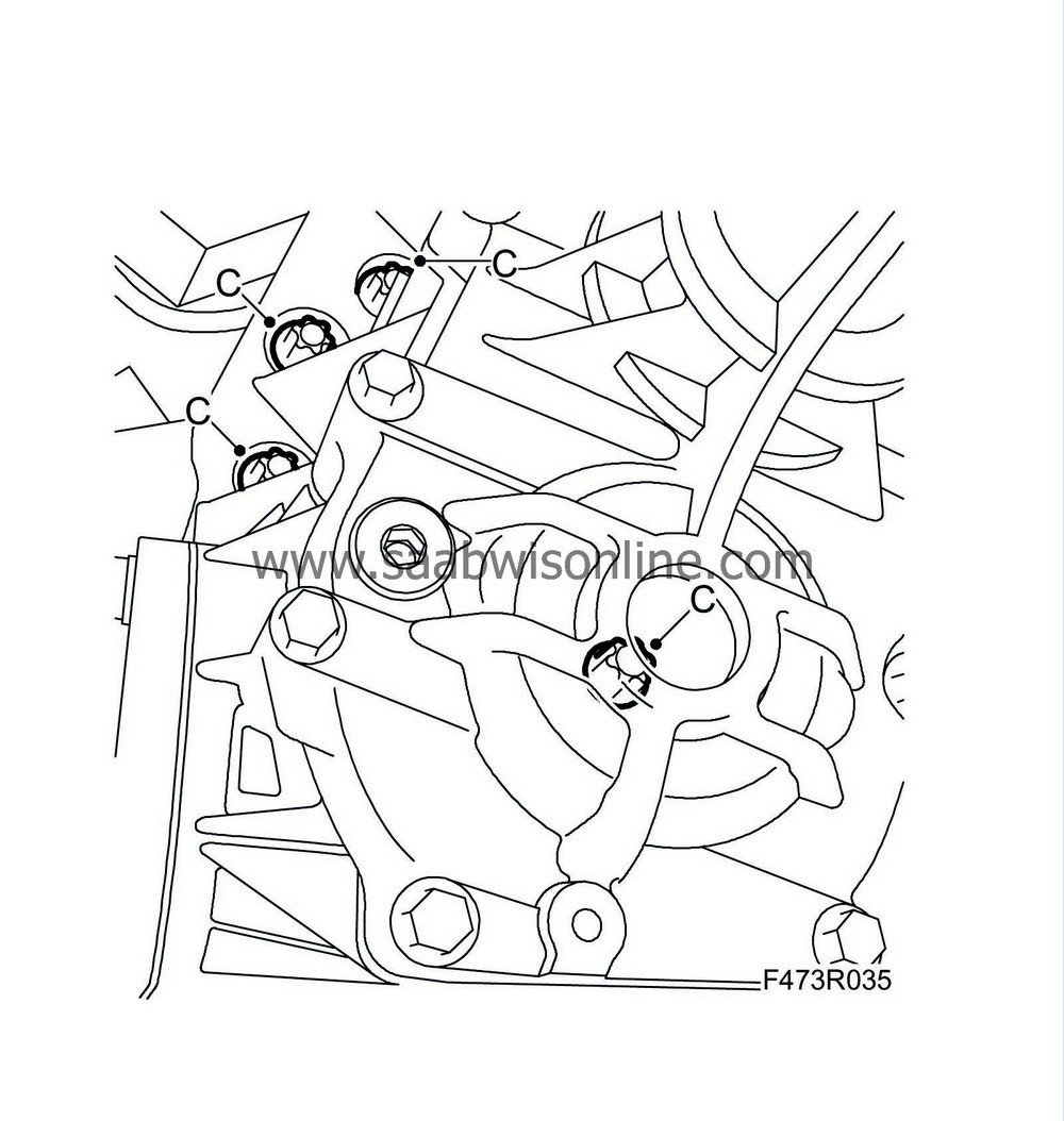
|
|
| 30. |
Remove the transfer case.
|
|
| 31. |
Aut:
Pull out the gearbox approx. 10 mm.
|
|
| 32. |
Aut:
Remove the plug, press the torque converter toward the gearbox and fit
87 92 574 Holder
to hold the torque converter in place while the gearbox is removed.
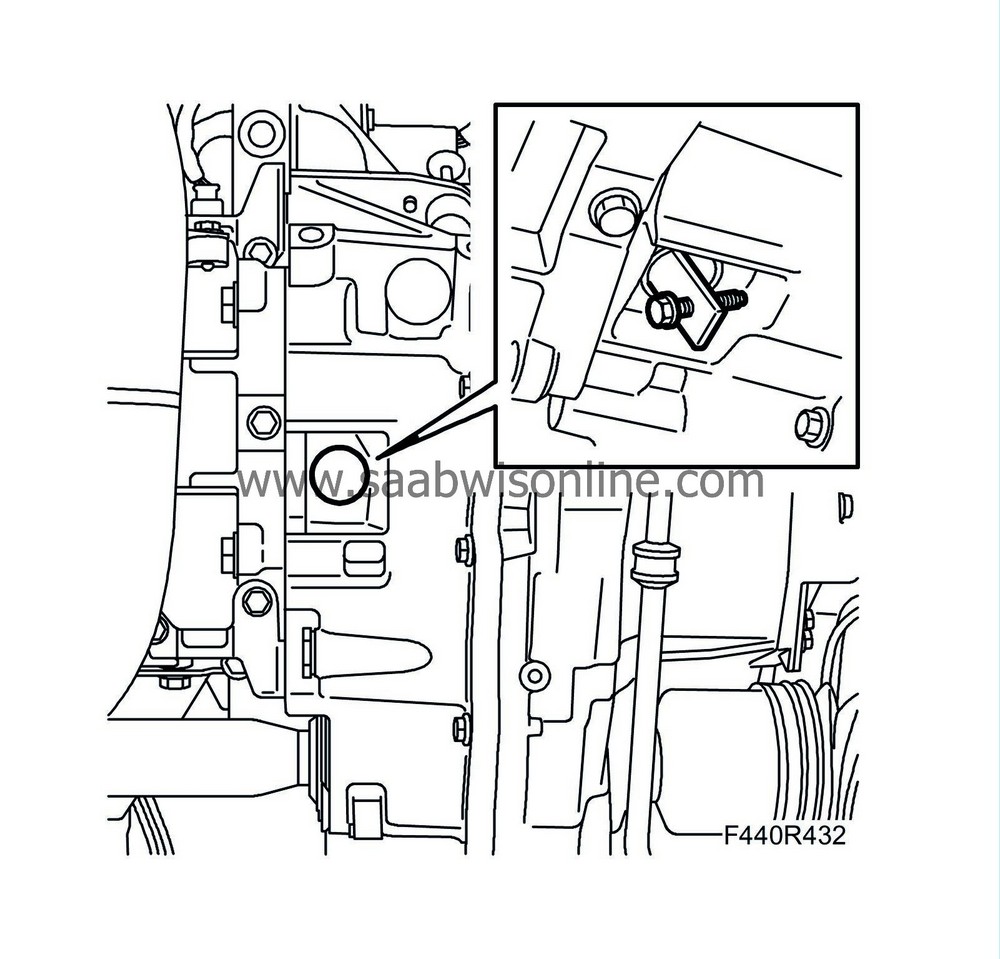
|
|
| 33. |
Remove the lower retaining bolts (A) of the gearbox.
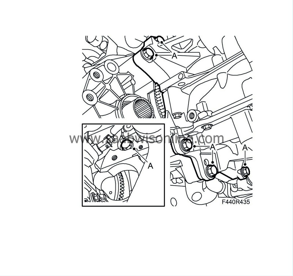
|
|
| 34. |
Carefully lower the engine onto a pallet.
|
|
| 35. |
Remove the upper retaining bolts (A) of the gearbox.
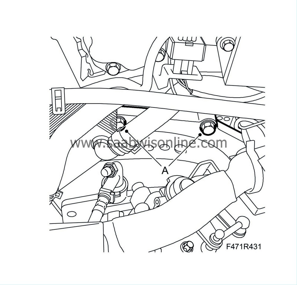
|
|
| 36. |
Fit
87 92 442 Lifting cable
to the gearbox and raise the gearbox slightly. Remove the gearbox from the engine.
|
|
| 37. |
Lift up the engine and fit
83 94 751 Holder, engine
. Fit the engine to the floor stand
78 74 878 Floor stand
.
|
|
| 38. |
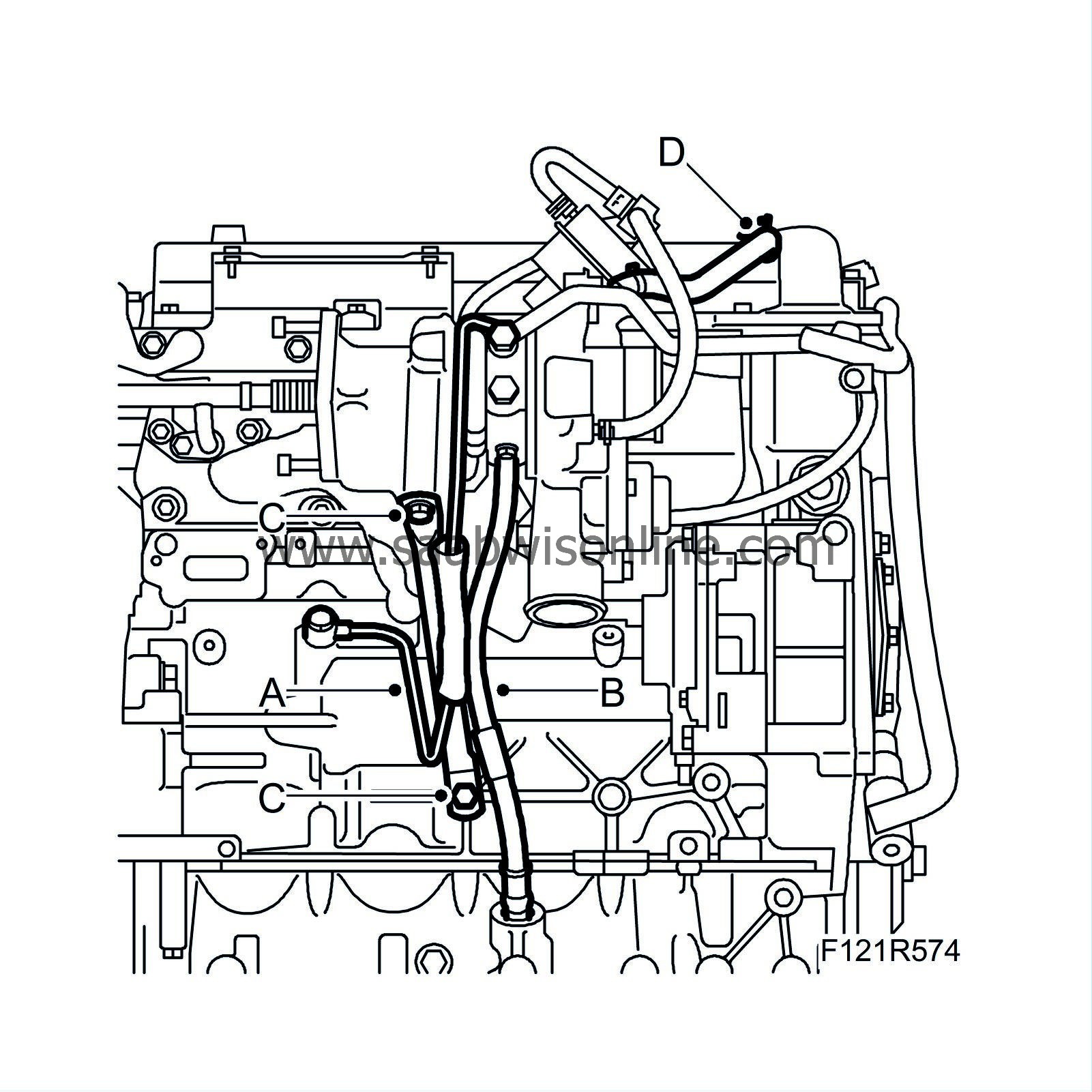
Remove the turbocharger oil delivery pipe (A).
|
|
| 39. |
Remove the turbocharger oil return pipe (B).
|
|
| 40. |
Remove the lower turbocharger attachment bracket (C).
|
|
| 41. |
Detach the crankcase ventilation hose (D) from the camshaft cover.
|
|
| 42. |
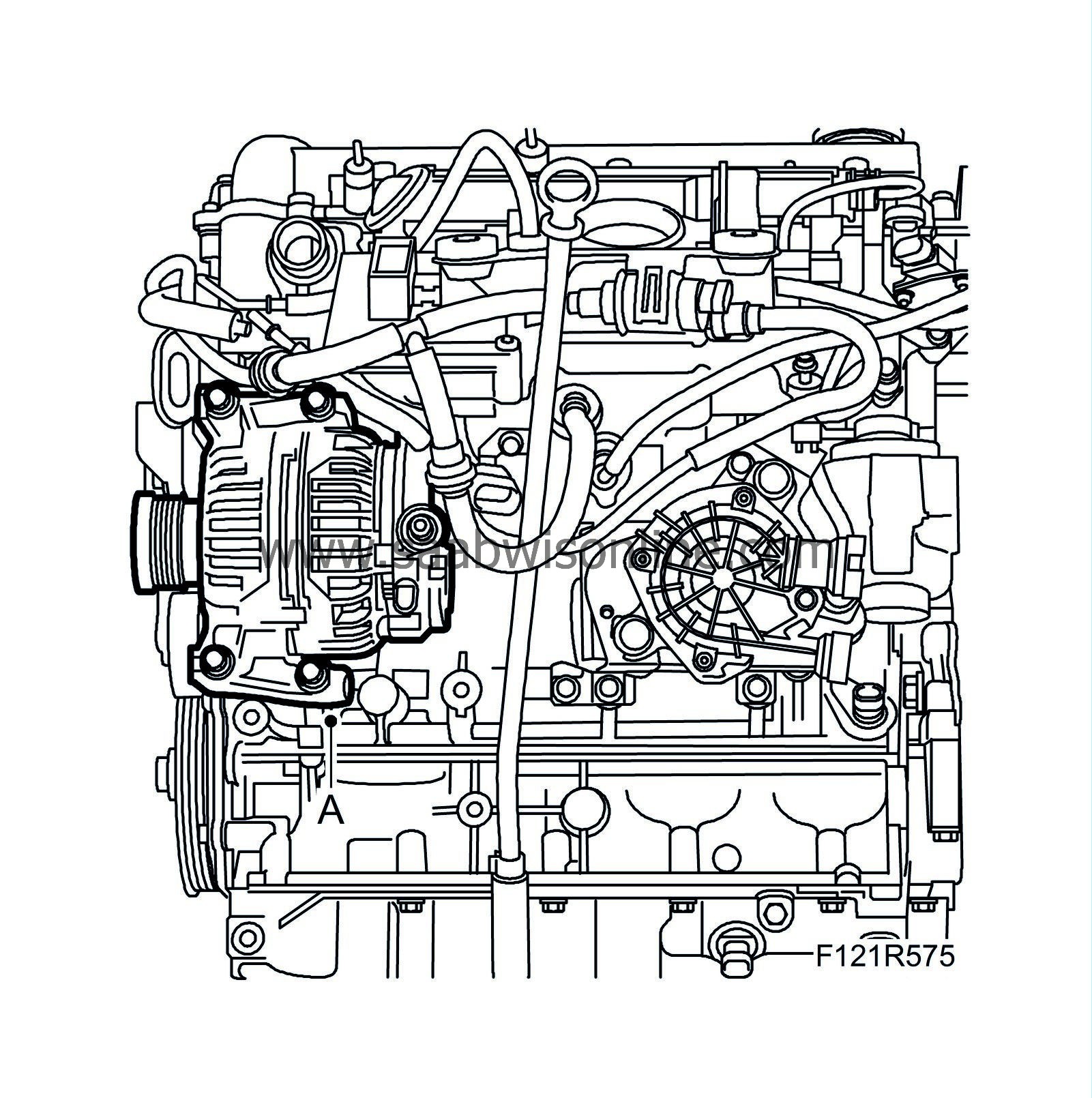
Remove the alternator (A).
|
|
| 43. |
Remove the lower intake manifold attachment bracket (A).

|
|
| 44. |
Remove the crankshaft position sensor (B).
|
|
| 45. |
Remove the bolt (C) from the dipstick tube.
|
|
| 46. |
Fit
83 94 868 Flywheel locking attachment
to secure the flywheel.
|
|
| 47. |
Man
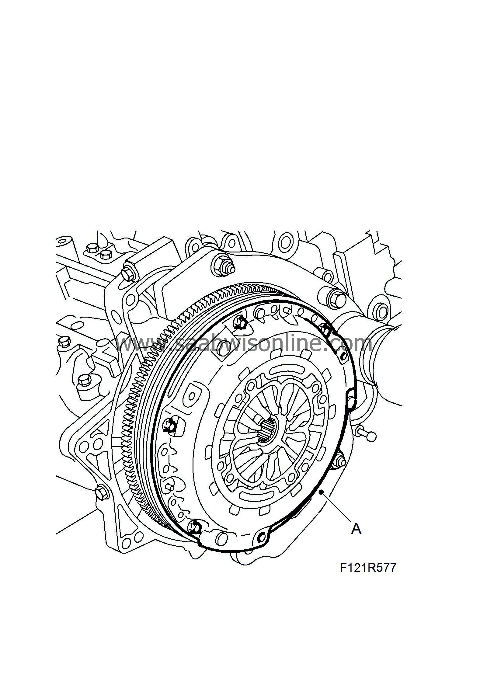
: Remove the bolts holding the pressure plate (A) and remove the clutch and driven plate hub.
|
|
| 48. |
Man:
Remove the flywheel (A).
Aut : Remove the driver plate. 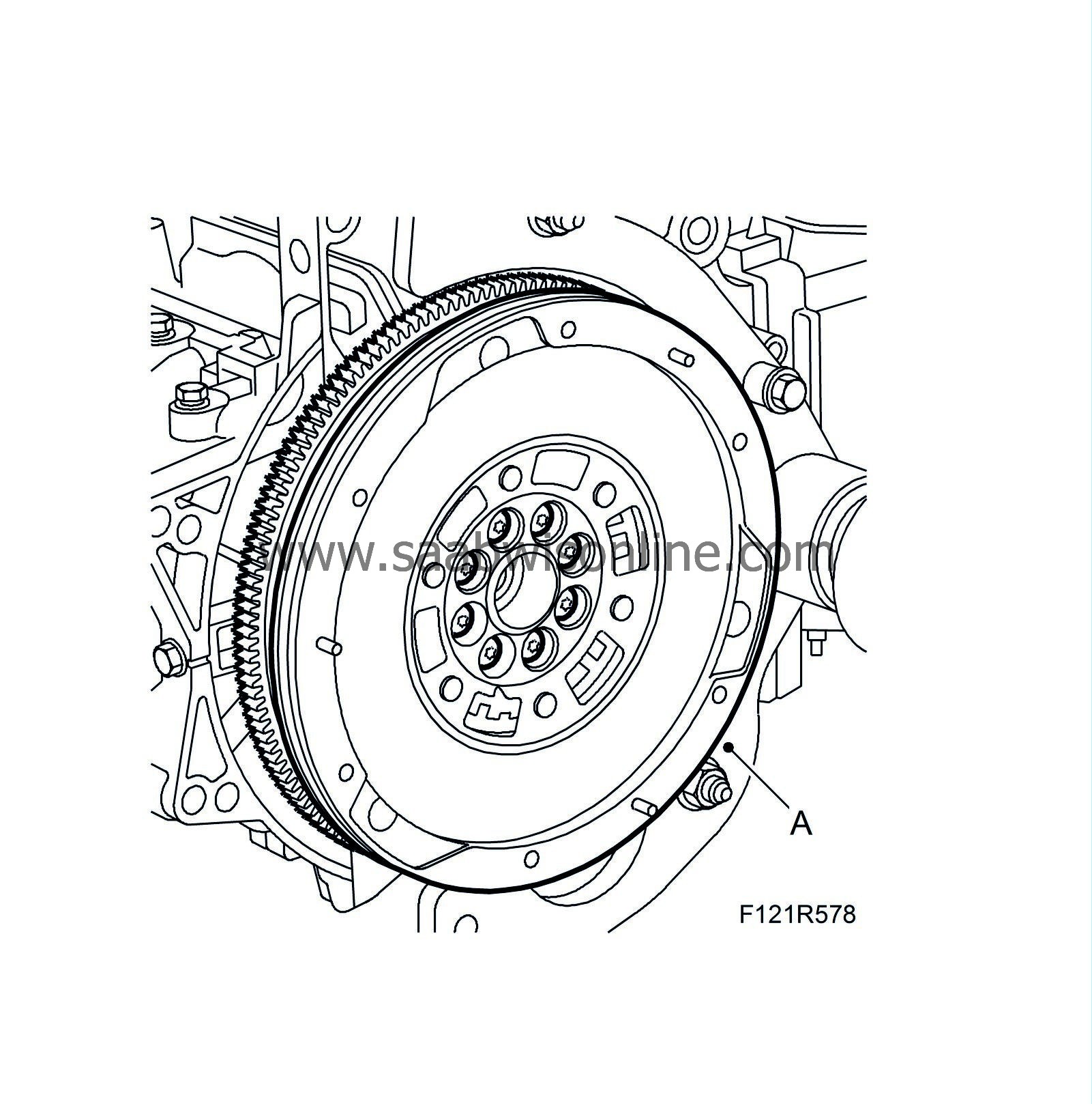
|
|
| 49. |
Remove
83 94 868 Flywheel locking attachment
.
|
|
| 50. |
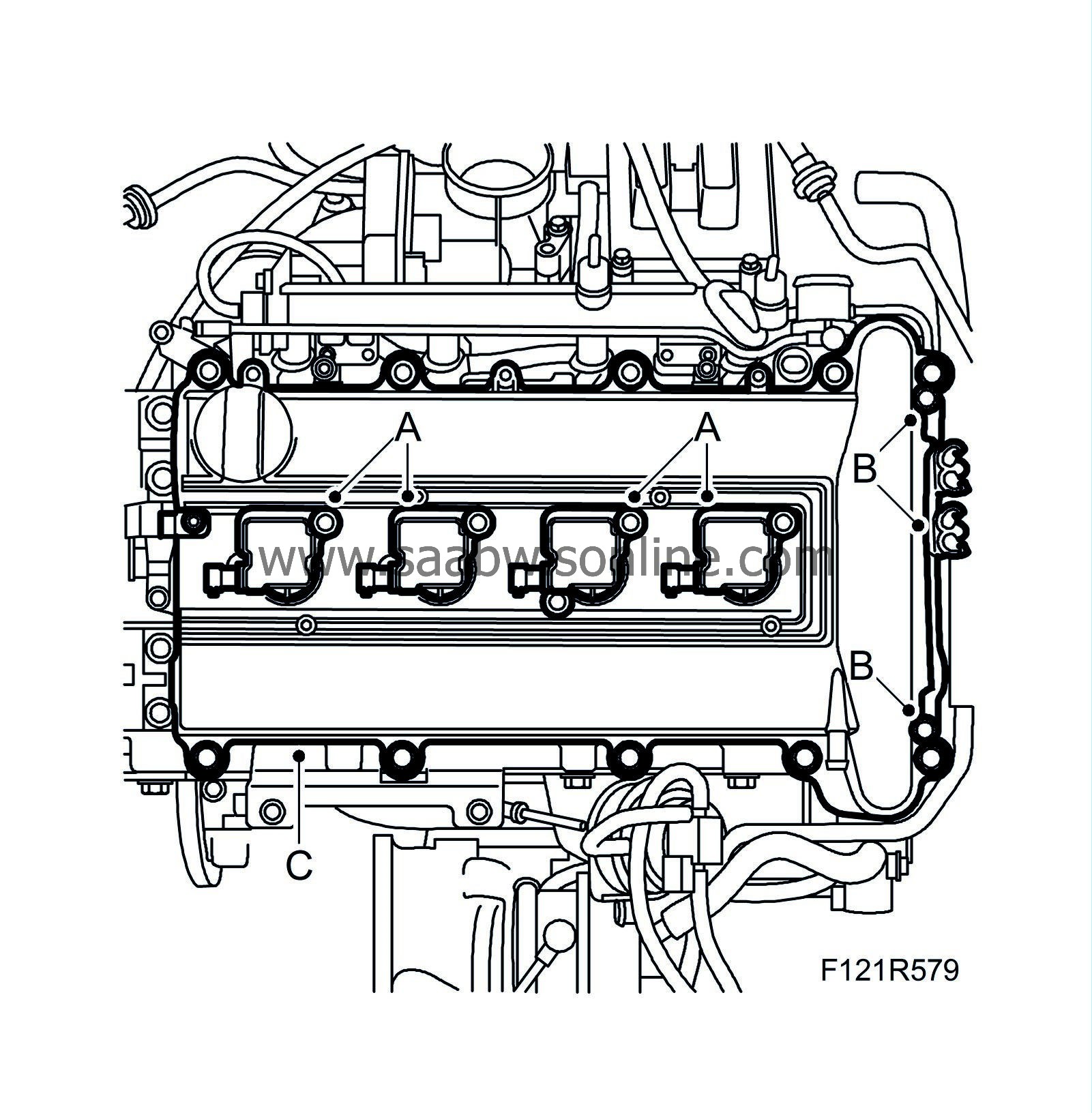
Remove the ignition coils (A).
|
|
| 51. |
Remove the bracket (B).
|
|
| 52. |
Remove the camshaft cover (C).
|
|
| 53. |
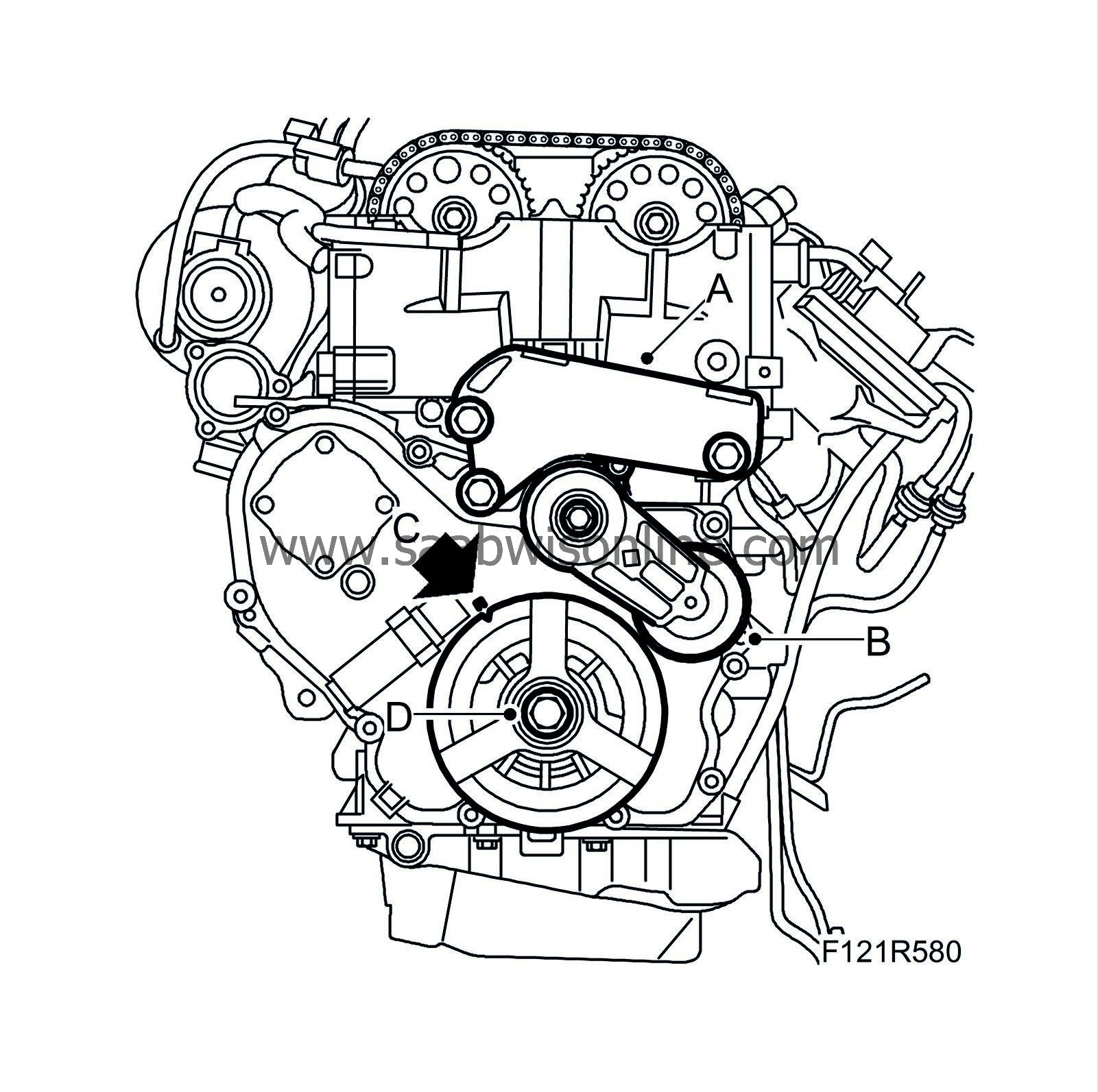
Remove the engine mounting bracket (A).
|
|
| 54. |
Remove the belt tensioner (B).
|
|
| 55. |
Zero the crankshaft (C). Remove the crankshaft pulley (D) using
83 95 360 Holding tool, crankshaft pulley
(handle only) and
83 96 210 Holding tool, crankshaft pulley, B207
.
|
|
| 56. |
Remove the timing cover (A) and gasket.

|
|
| 57. |
Remove the crankshaft seal.
|
|
| 58. |
Remove the timing chain tensioner (B).
|
|
| 59. |
Remove the plug (C) from the cylinder head.
|
|
| 60. |
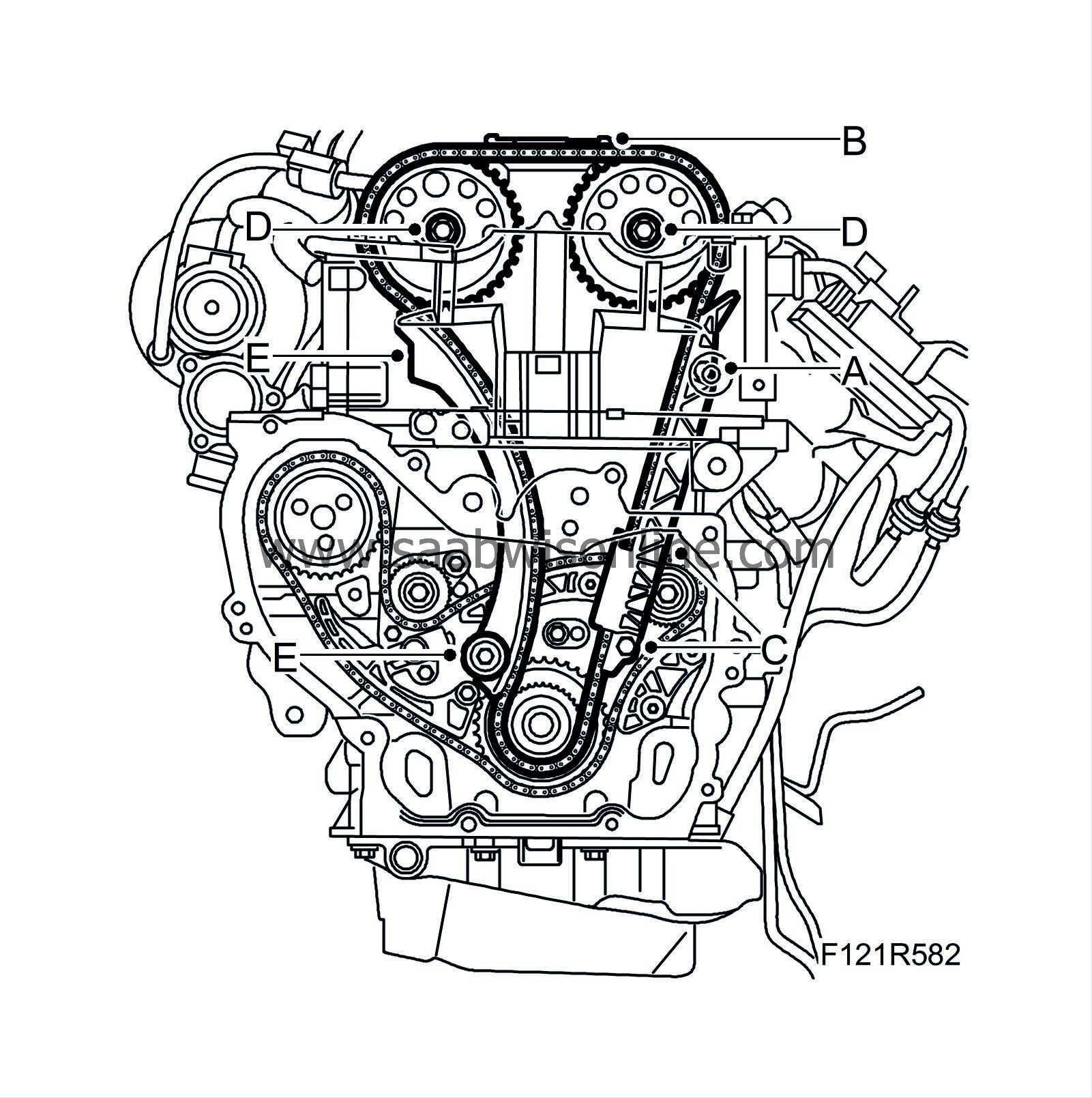
Remove the upper bolt (A) from the chain guide near the intake side.
|
|
| 61. |
Remove the upper timing chain guide rail (B).
|
|
| 62. |
Remove the lower chain guide bolt (C). Pull the chain guide down. Detach the lower section of the chain.
|
|
| 63. |
Remove the camshaft sprockets (C). Use a wrench to grip the camshaft flats when the bolts are loosened. Lift up the chain.
|
|
| 64. |
Remove the tensioner guide (E) by lifting it up. Inspect the condition of the guide. Replace if necessary.
|
|
| 65. |
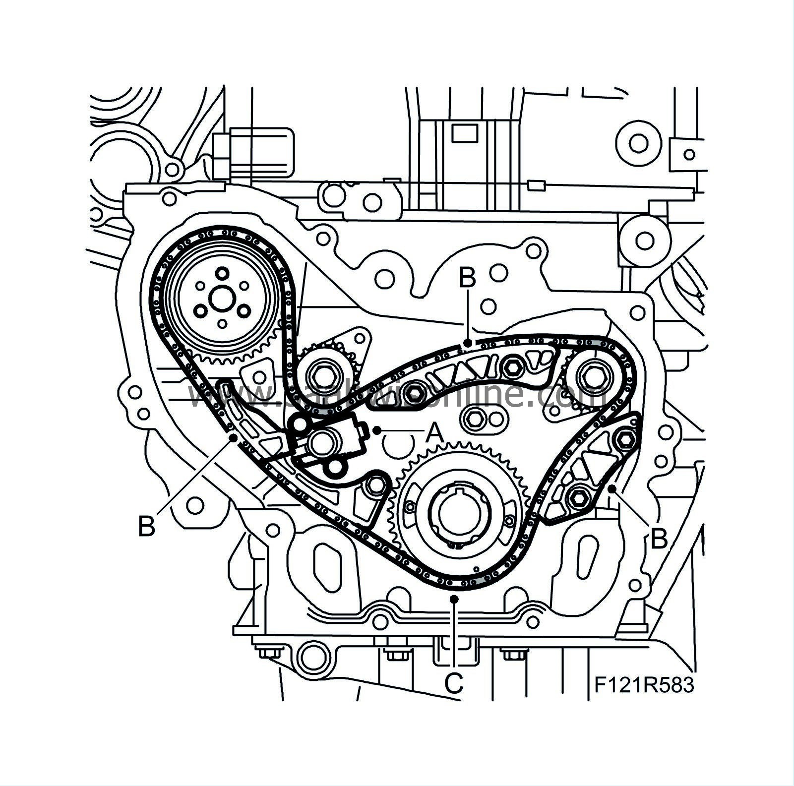
Remove the balancer shaft chain tensioner (A).
|
|
| 66. |
Remove the balancer shaft chain guide bars (B).
|
|
| 67. |
Remove the balancer shaft chain, sprocket and wedge (C).
|
|
| 68. |
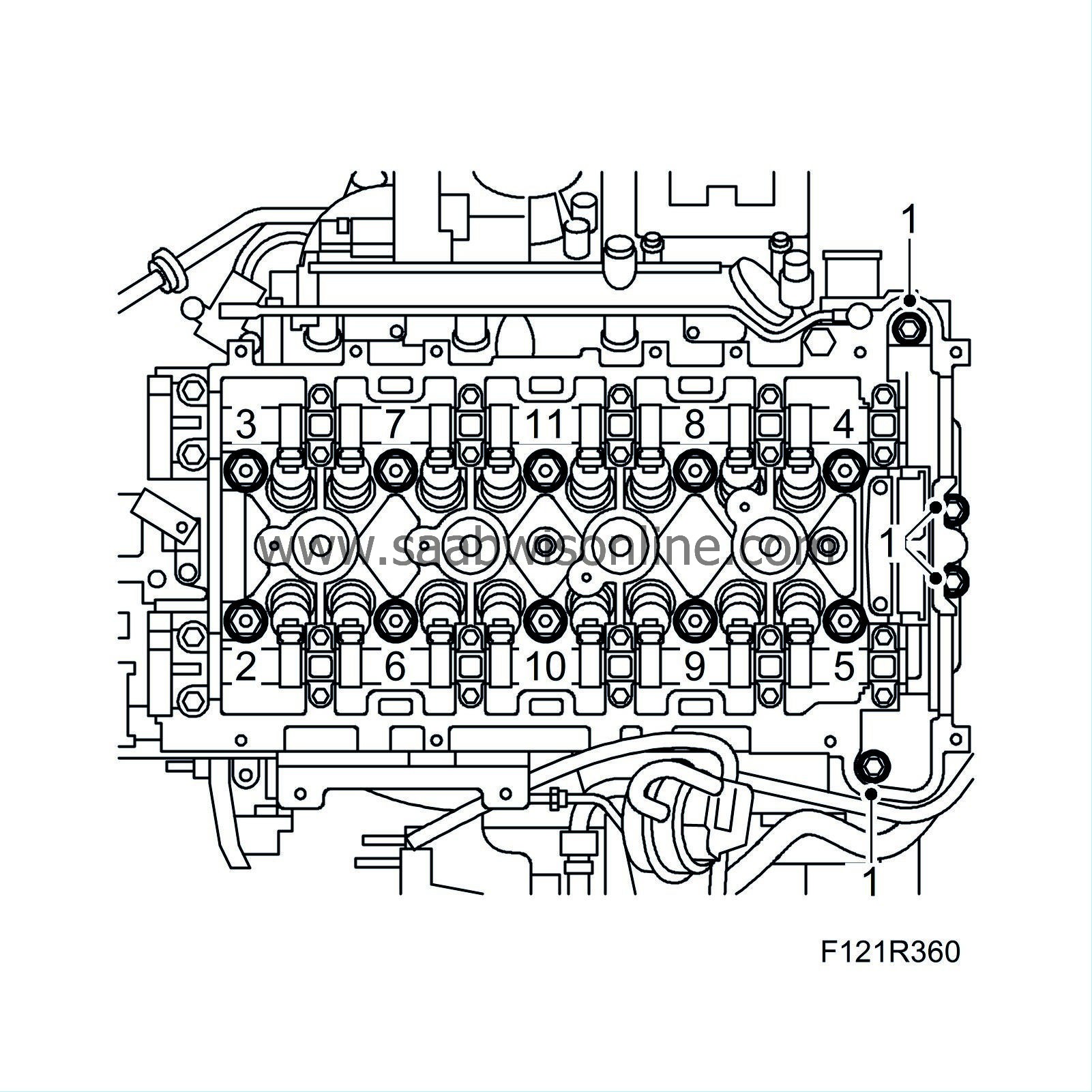
Remove the cylinder head in the order shown in the illustration.
|
|
| 69. |
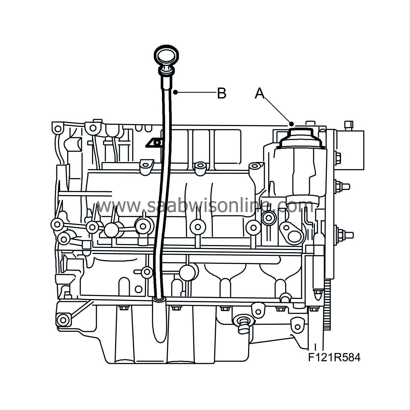
Remove the oil filter cover (A).
|
|
| 70. |
Remove the dipstick tube (B).
|
|
| 71. |
Lift down the cylinder block from
78 74 878 Floor stand
and remove
83 94 751 Holder, engine
.
|
|

 Warning
