Test readings, control module connections, SID
|
|
Test readings, control module connections, SID
|
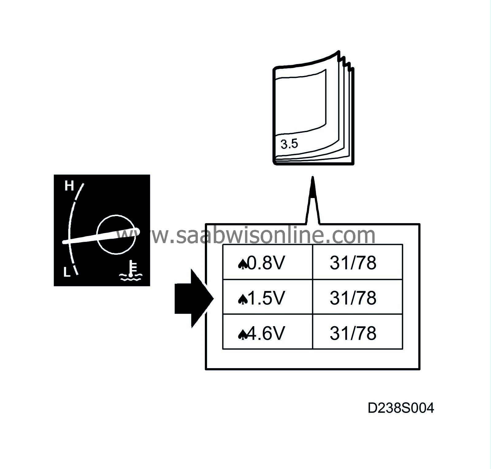
Values and instructions for measuring SID unit voltage levels are found under each section heading.
|
•
|
Note the test conditions and use common sense when assessing test results.
|
|
•
|
The test readings presented are with the ignition in position ON unless otherwise specified.
|
|
•
|
First check that the control module has a power supply and is grounded.
|
|
•
|
Then check all sensor inputs and signals from other systems.
|
|
•
|
Lastly, check the control module outputs. Remember, the readings do not say anything about whether or not the actuator is in working order.
|
|
•
|
If any reading is not OK, consult the wiring diagram to trace the leads, connectors or components which should be checked more thoroughly.
|
|
•
|
The specified test readings refer to those obtained with a calibrated Fluke 88/97.
|
|
•
|
Test readings % (+) and ms (+) show the signal's pulse ratio and pulse width. A test instrument with pulse ratio and pulse width measurement must be used. The sign (+) indicates a positive trigger pulse, TRIG+.
|
>= greater than; <= less than; ~= alternating current
A pin with no additional comments has no pin connection (LP: LOGIC PROBE P= select pulse; p= visible pulses)
|
Pin No.
|
Cable colour
|
Component/function
|
In/Out
|
Test conditions
|
Across
|
Test reading
|
See
|
|
20
|
BU/RD
|
Parking heater / Auxiliary heater
|
Out
|
Activated
|
20-1
|
0 V
|

|
|
|
|
|
|
Not activated
|
20-1
|
B+
|
|


