Power train, to remove, 4WD
|
|
Power train, to remove, 4WD
|
 Warning
|
|
A large number of hoses, cables, etc., are secured with cable ties. After tightening, the ties are cut off and leave more or less sharp edges at the fastening point. Watch out for the risk of cuts due to these sharp ends on the cable ties!
|
|
|
|
|
|
|
1.
|
Place the car on a lift and apply wing covers.
|
Warning
|
|
The cooling system is under pressure. Hot coolant and steam can escape.
|
|
- Open the cap slowly to release the pressure.
|
|
- Carelessness can cause eye and burn injuries
|
|
|
|
|
|
|
|
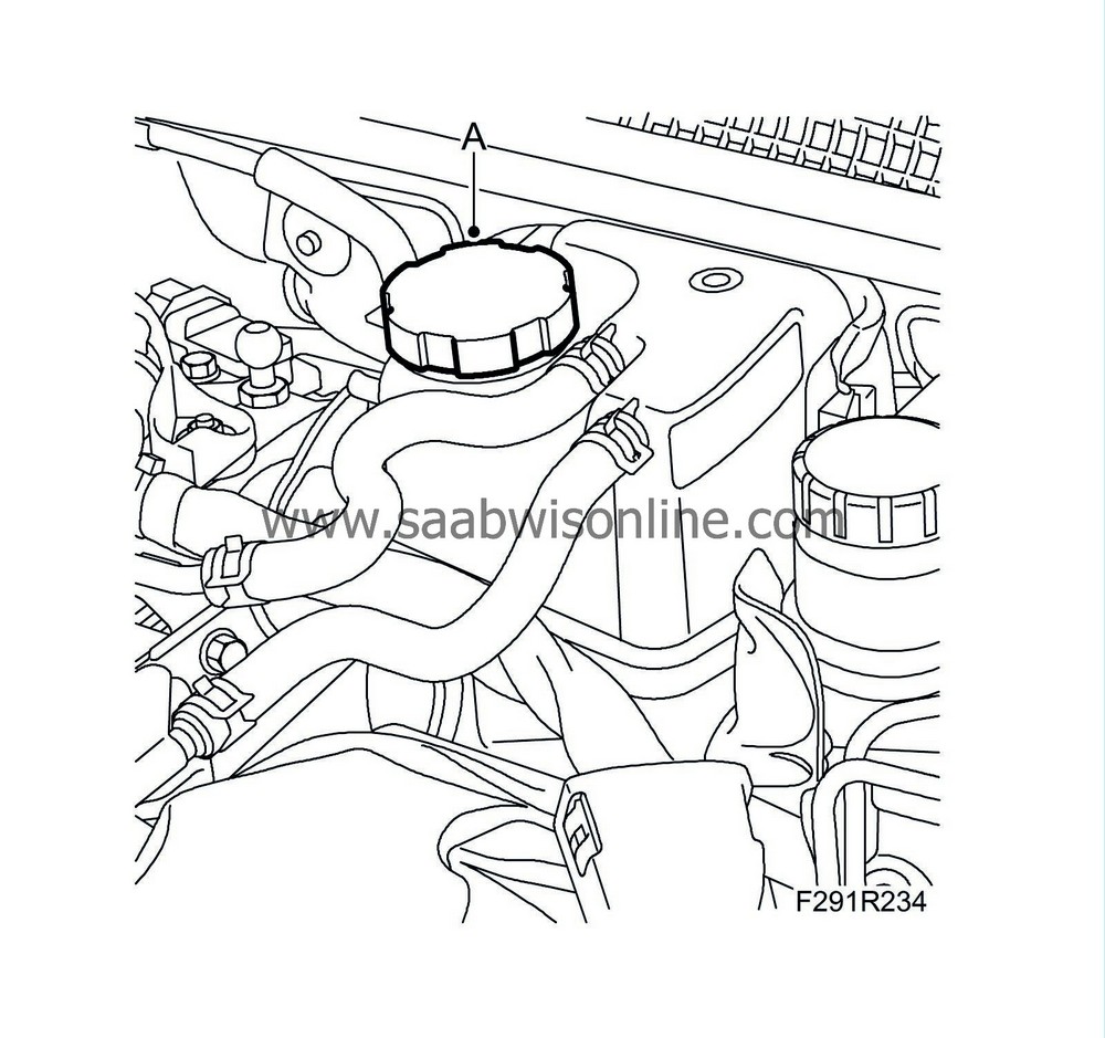
2.
|
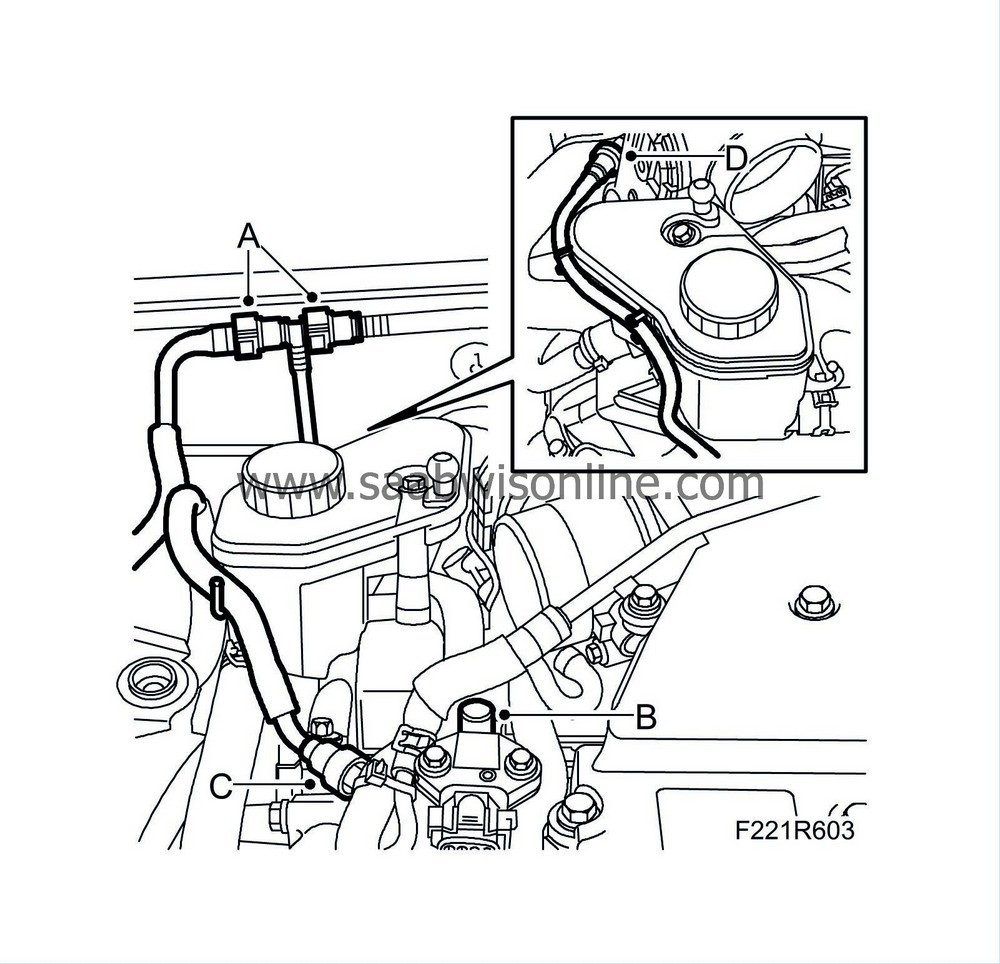
Take the cap (A) off the expansion tank to release any pressure.
|
|
3.
|
Remove the battery cover and disconnect the negative cable.
|
|
4.
|
Raise the car slightly and remove the front wheels.
|
|
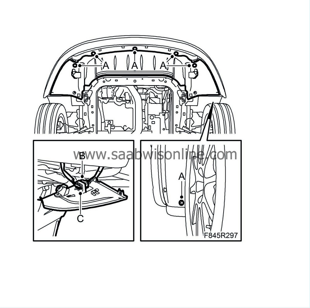
5.
|
Remove the spoiler shield bolts (A). Unplug the connector (B) and remove the other connector (C).
|
|
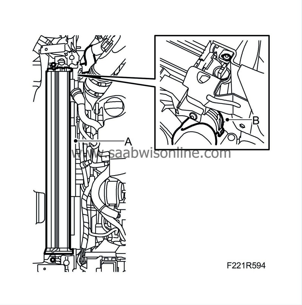
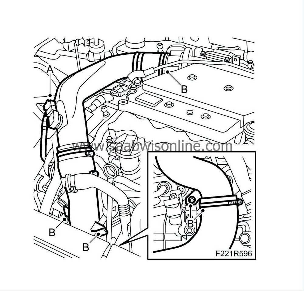
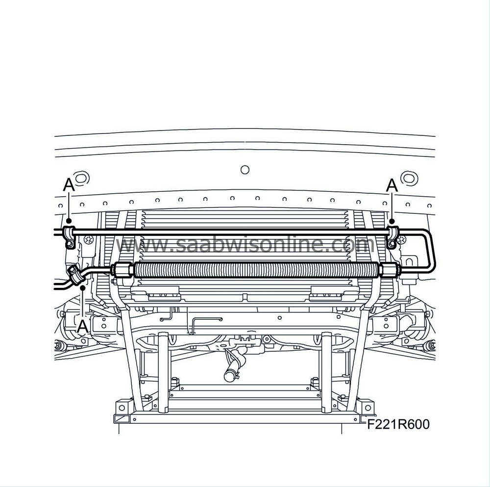
6.
|
Position a container under the car, connect a hose (A) to the radiator (B) and drain the coolant.

|
|
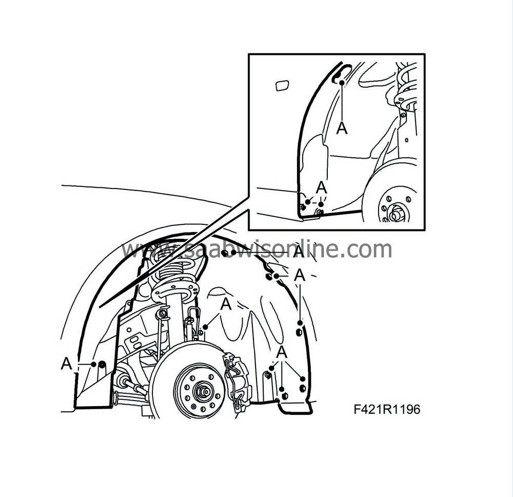
7.
|
Remove the right wing liner (A) and detach the front part of the left wing liner.
|
|
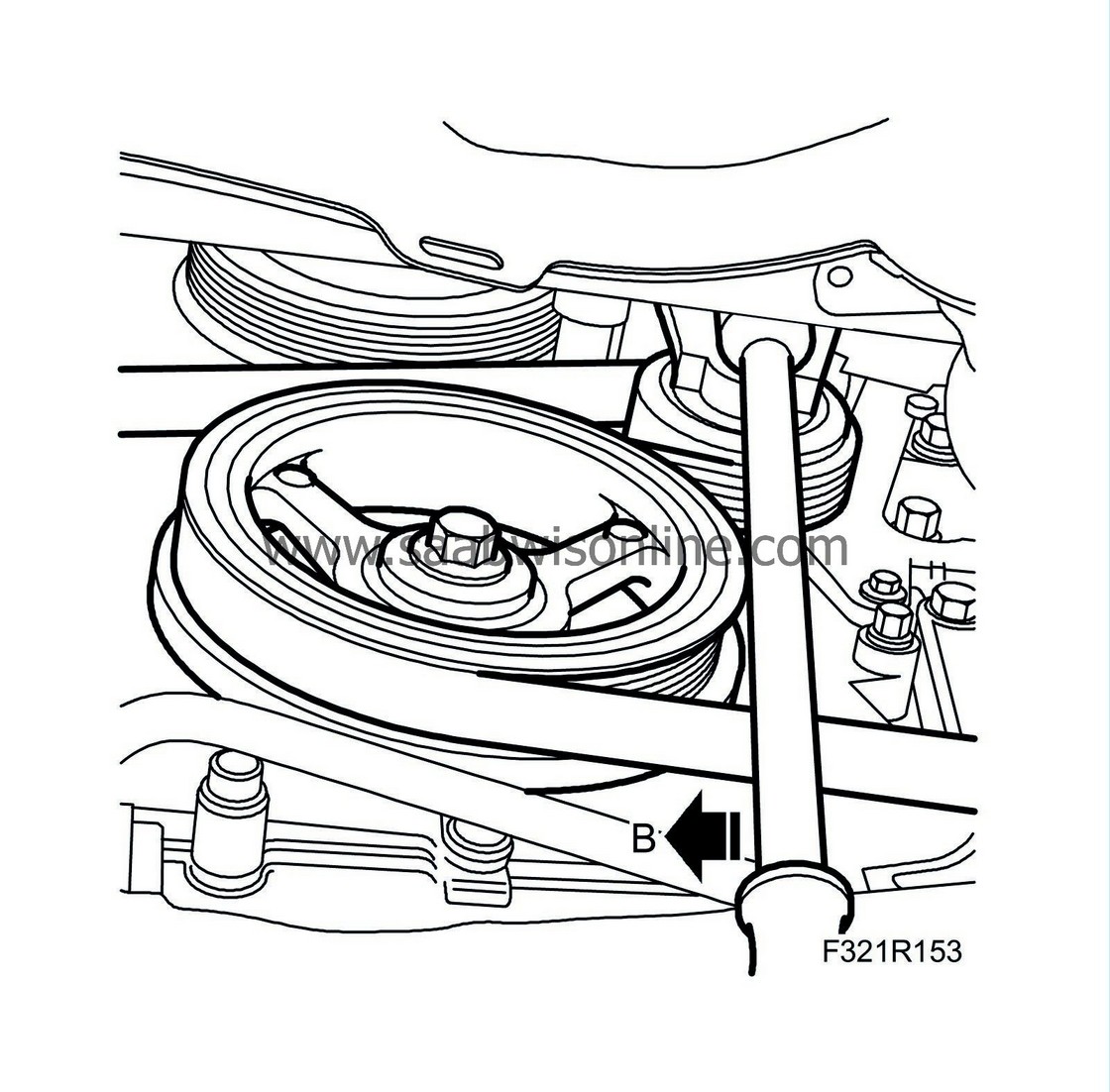
8.
|
Unload the belt tensioner. Use a ¼" puller (B) and remove the drive belt from the AC compressor pulley.
|
|
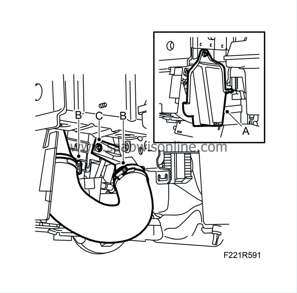
10.
|
Remove the cover (A) on the left-hand side.
|
|
11.
|
Remove the charge air hose (B) between the charge air pipe and the charge air cooler and remove the lower charge air pipe bracket (C) from the fan cowling.
|
|
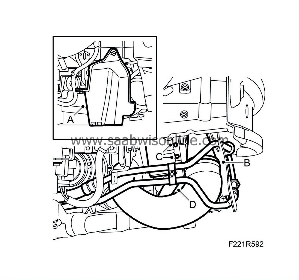
12.
|
Remove the cover (A) on the right-hand side.
|
|
13.
|
Detach the hose (B) from the charge air cooler.
|
|
14.
|
Remove the dryer filter bolts (C) from the radiator.
|
|
15.
|
Detach the oil cooler's coolant hose (B) from the radiator.
|
|
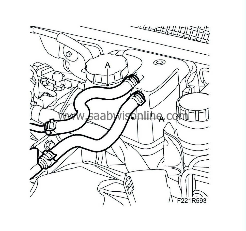
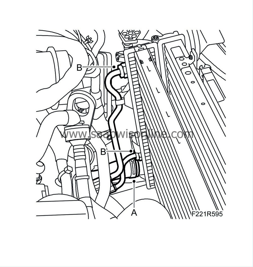
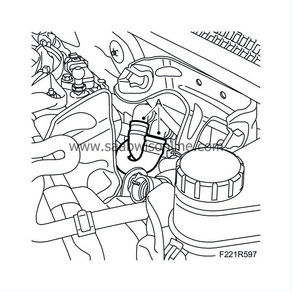
17.
|
Lower the car and detach the breather hoses (A) from the coolant reservoir.
|
|
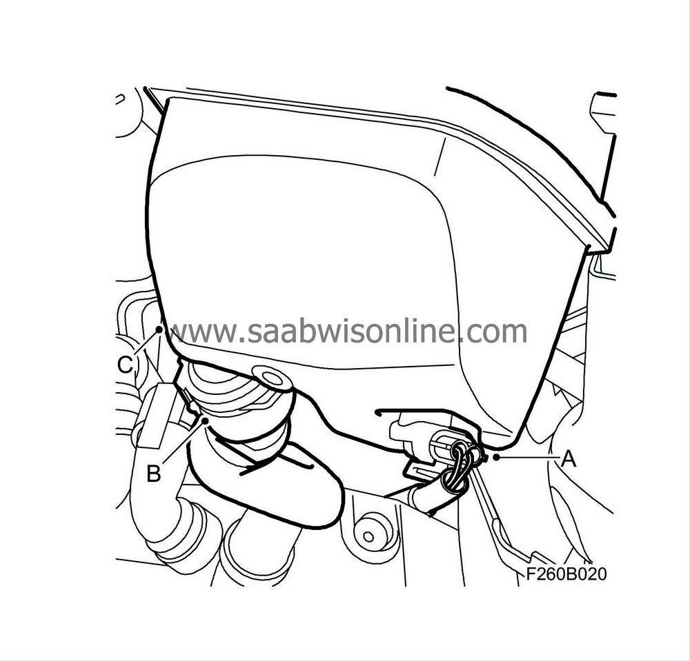
18.
|
Bend up the coolant reservoir and unplug the level sensor connector (A) and the quick coupling of the hose (B). Move aside the coolant reservoir (C).
|
|
19.
|
Remove the upper engine cover.
|
|
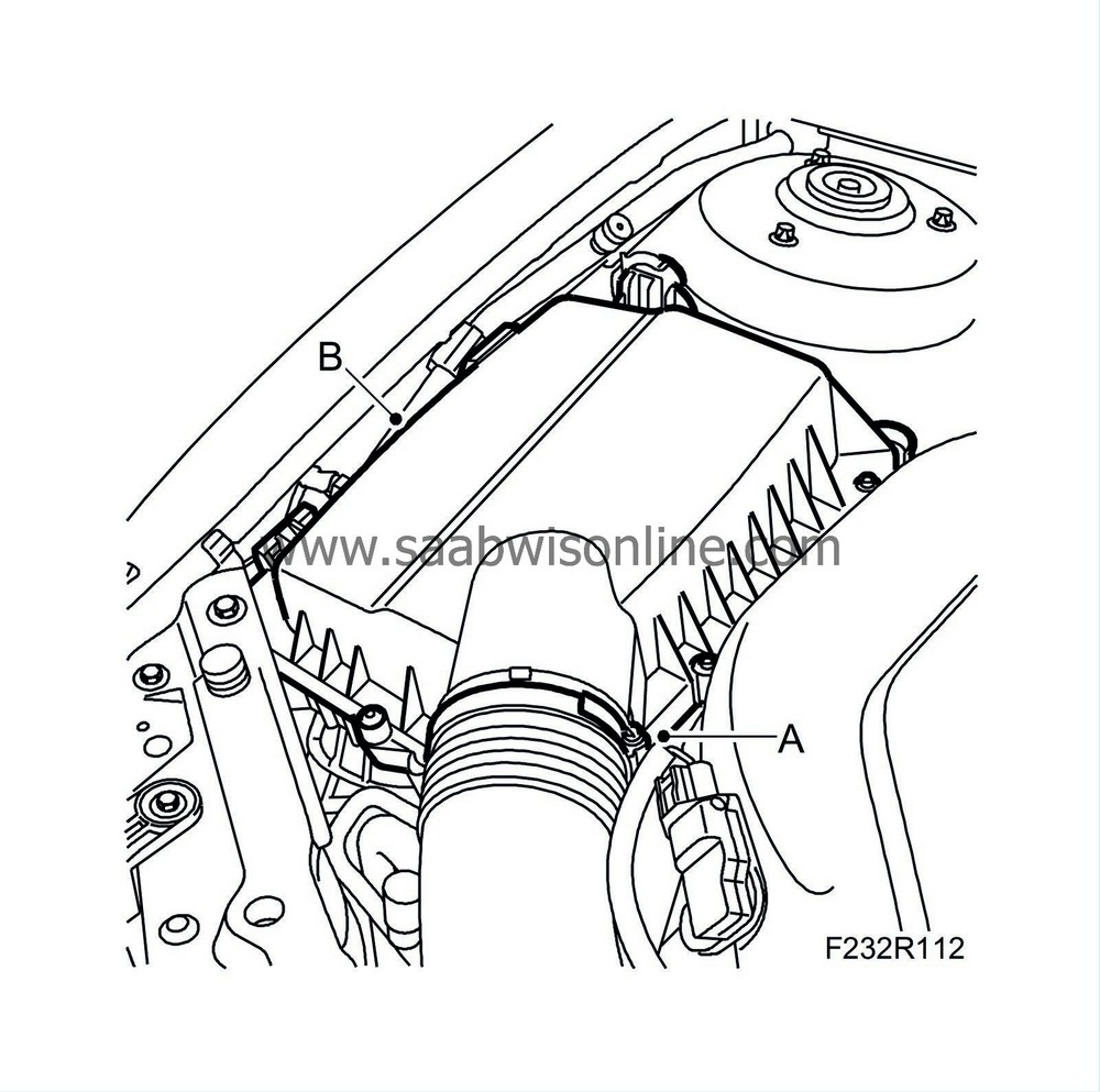
21.
|
Undo the pipe from the air cleaner casing cover (A) and remove the cover (B).
|
Important
|
|
When removing the air cleaner casing cover, be careful not to damage the brake vacuum pump sensor.
|
|
|
|
|
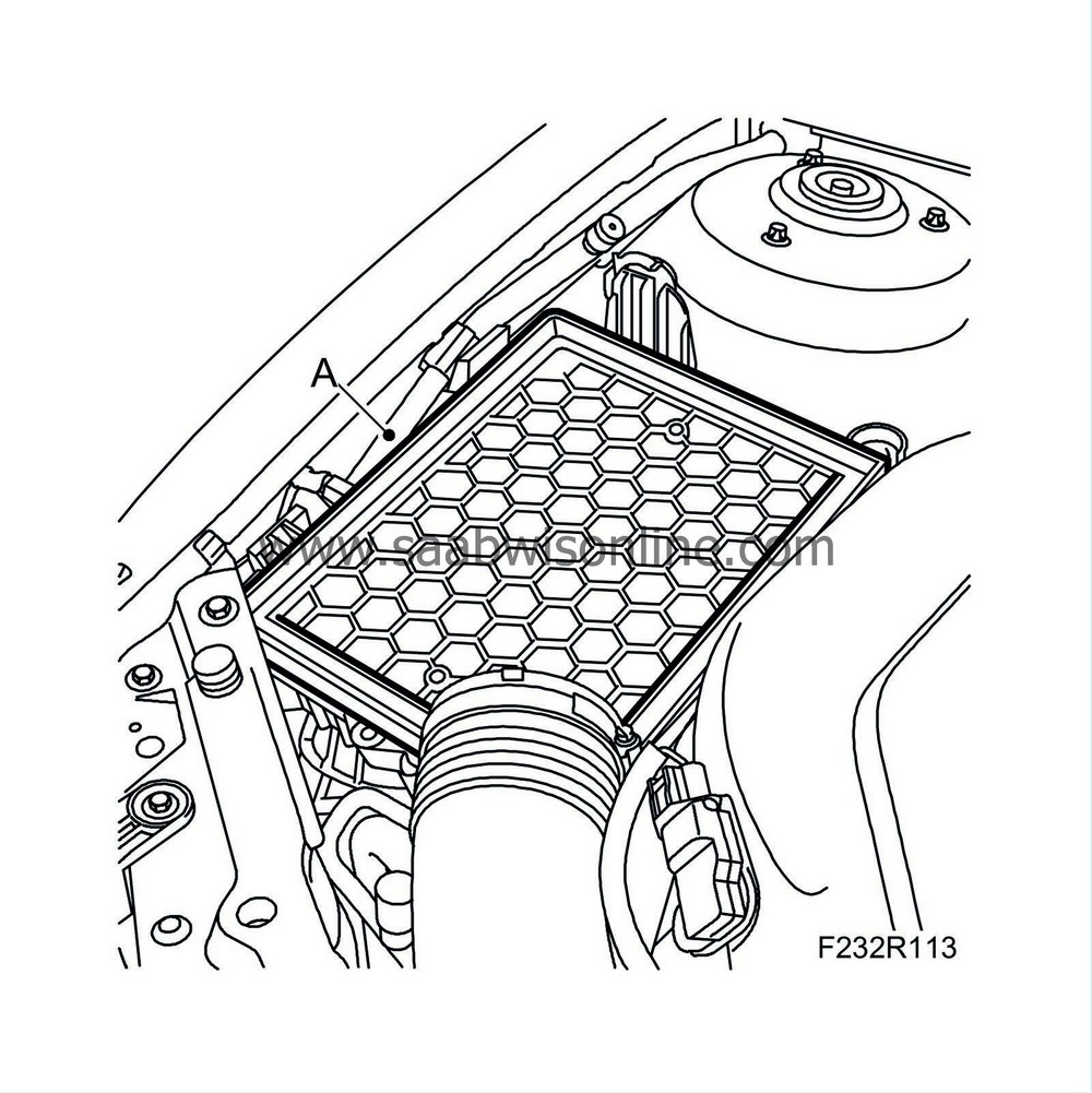
22.
|
Remove the filter element (A).
|
|
23.
|
Remove the air cleaner casing lower section. Press out the intake manifold so that it becomes loose before the air cleaner casing is lifted out.
|
|
24.
|
Remove the cover (A) over the radiator assembly.
|
|
25.
|
Detach the upper radiator hose (B) from the engine.
|
|
26.
|
Place a receptacle under the radiator and remove the lower radiator hose (A).
Aut:
Detach the oil pipes of the radiator (B) using 87 92 806 Removal tool, automatic transmission oil pipes. Plug the pipes.
|
|
27.
|
Detach the boost pressure sensor connector (688) (A).
|
|
28.
|
Remove the charge air pipe (B) between the throttle body and charge air cooler.
|
|
29.
|
Remove the coolant connections (A) from the radiator assembly.
|
|
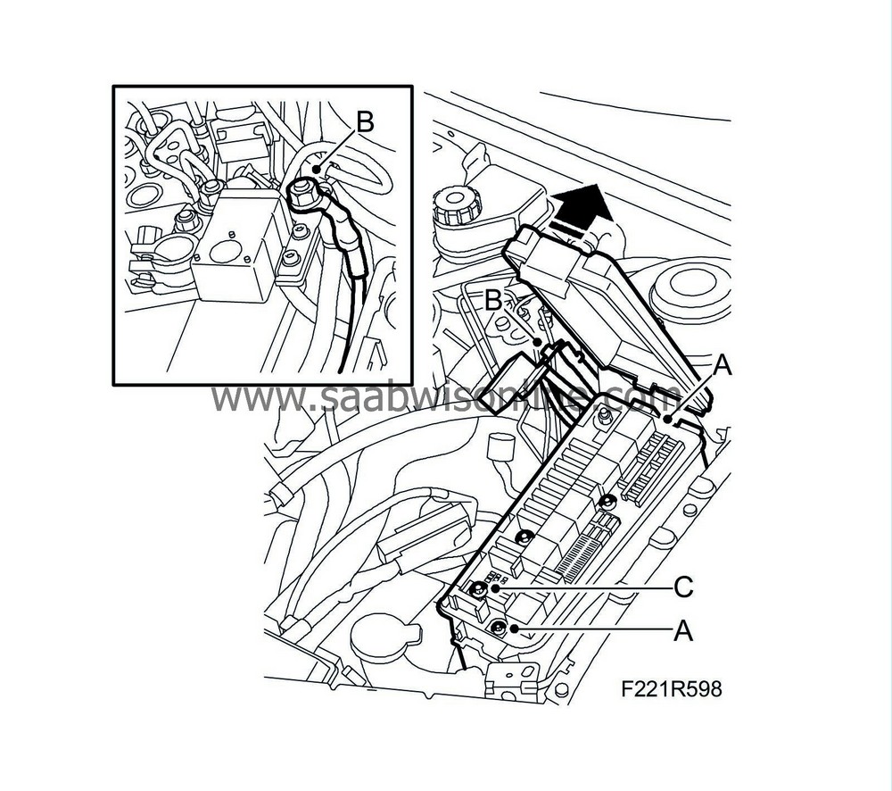
30.
|
Remove the cover on the main fuse box and undo the two retaining screws (A).
|
|
31.
|
Disconnect the positive cable (B) from the positive battery terminal.
|
|
32.
|
Undo the retaining screw on the engine harness connector(C) in the main fuse box.
|
|
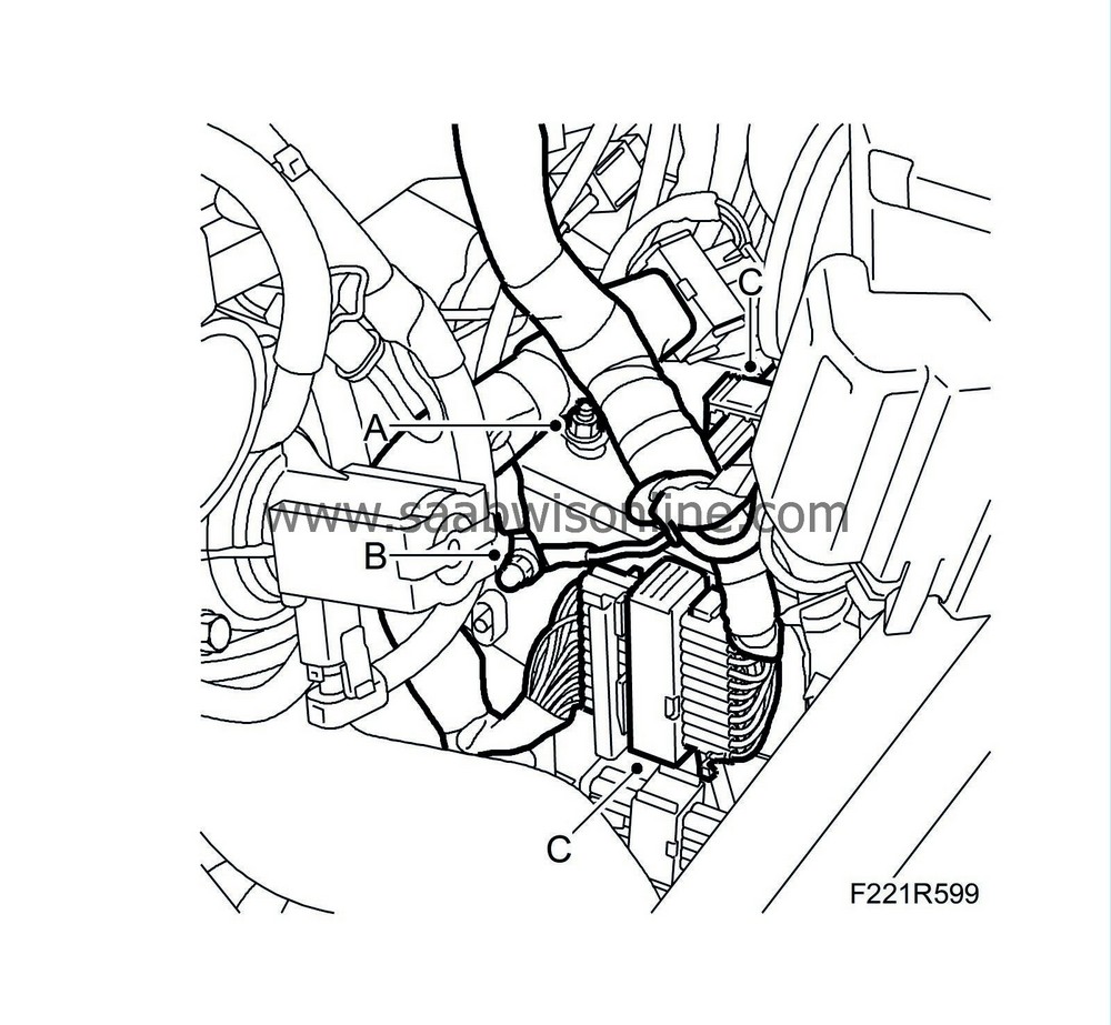
33.
|
Remove the engine harness clamp (A) from the body and detach the ground cables (B).
|
|
34.
|
Unplug the two connectors (C) on the structural member.
|
|
35.
|
Move the engine harness up and secure it to the engine with a cable tie or the like.
|
|
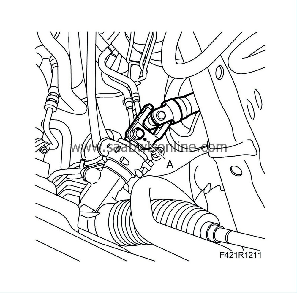
37.
|
Detach the steering shaft (A) from the steering gear.
|
|
38.
|
Detach the power steering pipes (A) from the radiator assembly.
|
|
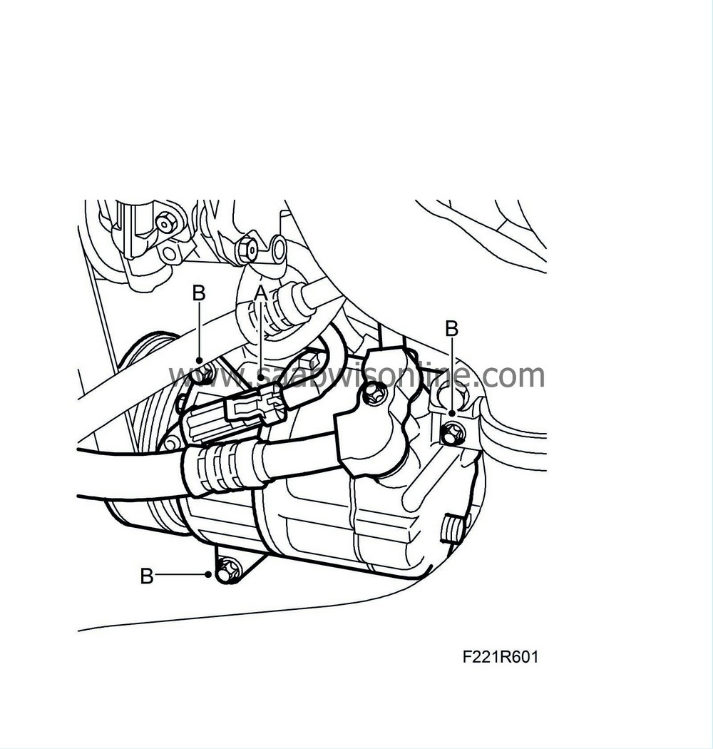
39.
|
Unplug the A/C compressor connector (A) and remove the A/C compressor retaining bolts (B).
|
|
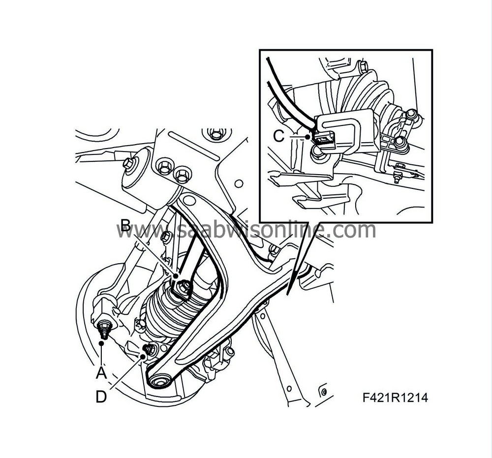
42.
|
Undo the nuts (A) and detach the outer steering links from the steering swivel members using
87 91 287 Puller, 150 mm
.
|
|
43.
|
Undo the lower anti-roll bar links (B) while gripping the flats with a thin spanner.
|
|
44.
|
Certain cars:
Unplug the connector (C) of the headlamp angle sensor and detach the cable from the subframe.
|
|
45.
|
Undo the lower swivel joints (D) from the steering swivel members and pivot down the suspension arms.
|
|
47.
|
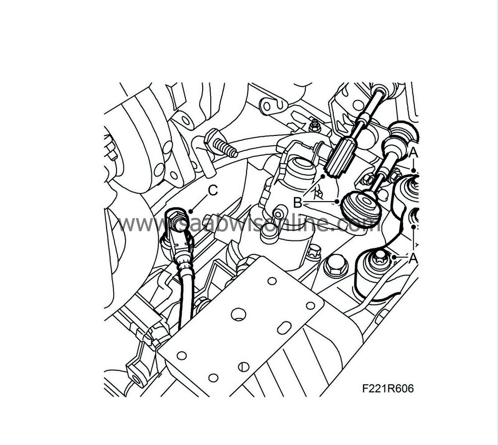
Detach the brake servo vacuum pipe (A) and move it aside.
|
|
48.
|
Relieve excess pressure in the fuel system by carefully pressing on the needle of the service valve (B). Catch any fuel spill. Detach the fuel line (C) from the fuel rail. Plug the fuel lines using
82 92 948 Plugs, A/C system, kit
.
|
|
49.
|
Release the quick coupling (D) of the breather line and move it aside.
|
|
50.
|
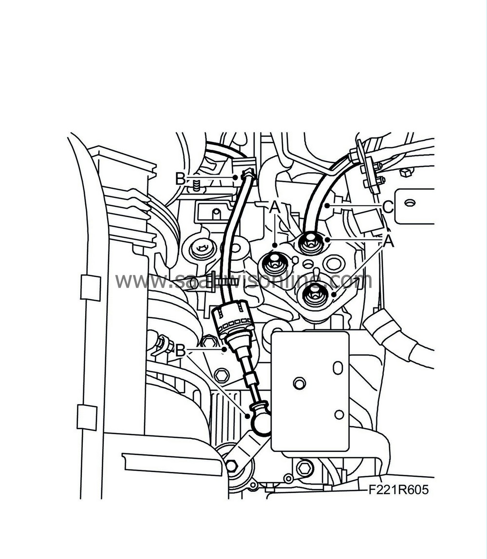
Remove the right engine mounting (A).

|
|
51.
|
Aut:
Remove the left engine mounting (A).
|
|
52.
|
Aut:
Detach the gear cable (B) from the gearbox; carefully move it aside and secure it to a brake pipe with a cable tie. Detach the breather hose (C) of the automatic transmission.
|
|
53.
|
Man:
Remove the left engine mounting (A).
|
|
54.
|
Man:
Remove the gear cables (B) from the gearbox; carefully move them aside and secure them to a brake pipe with a cable tie.
|
|
55.
|
Man:
Fit 30 07 739 Hose pinch-off pliers and remove the quick coupling (C) from the clutch slave cylinder.
|
|
56.
|
Place the radiator member back in position.
|
|
57.
|
Fit 2
83 95 212 Strap
in the radiator member in order to secure the radiator assembly. Insert one strap around the radiator assembly. Insert the other and wrap an extra loop around the A/C compressor in order to relieve the load. Place a cardboard disc or the like between the A/C compressor and the radiator as support.
|
|
58.
|
Place
83 96 152 Centring tool, power train
(KM 6313) on the trolley lift. Make sure the adjuster screws on the height adjusters, part no. 83 95 170, are in their lowest position. See Centring tool, engine and subframe.
|
|
59.
|
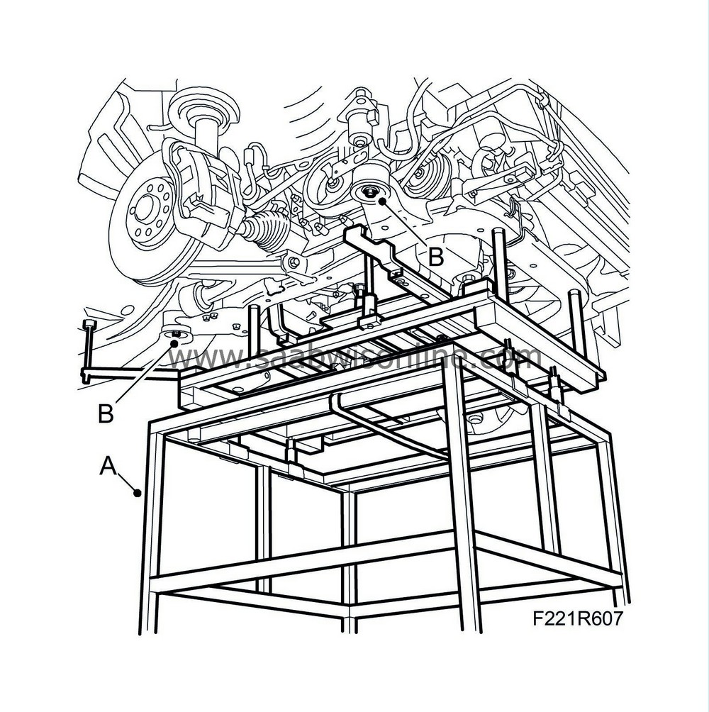
Position the trolley lift; raise and insert the guide pins in the subframe reference holes. Adjust the lifting pillars with the height adjusters, part no. 83 95 170, so that they rest evenly on the subframe. Check with the body guide pins that the subframe is positioned correctly in relation to the body (A). See Engine and subframe centring tool.
|
|
60.
|
Raise the trolley lift slightly to provide steady contact. Undo the rear bolts of the subframe stay and move the stay aside. Remove the subframe bolts (B) from the body.
|
|
61.
|
Carefully low the power train using the trolley lift. Detach the lower spindle joints from the steering swivel members and move aside the suspension arms. Make sure that nothing catches or gets damaged.
|


