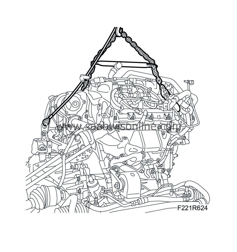
Replacing the engine (power unit on the subframe), 4WD
|
|
Replacing the engine (power unit on the subframe), 4WD
|
|
1.
|
Drain the oil from the engine and the fluid from the gearbox.
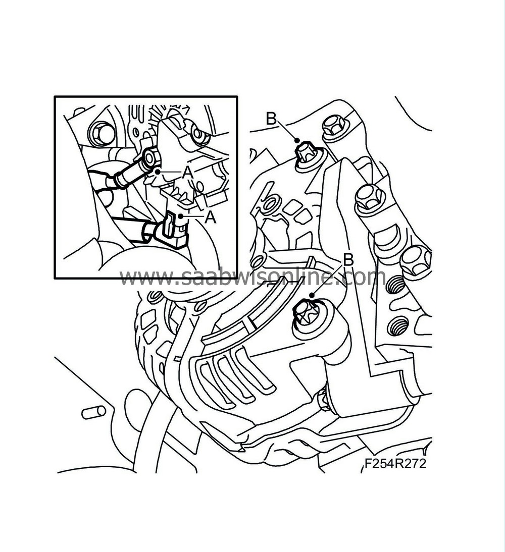
Disconnect the electrical connections of the alternator (A).
|
|
2.
|
Remove the alternator retaining bolts (B).
|
|
3.
|
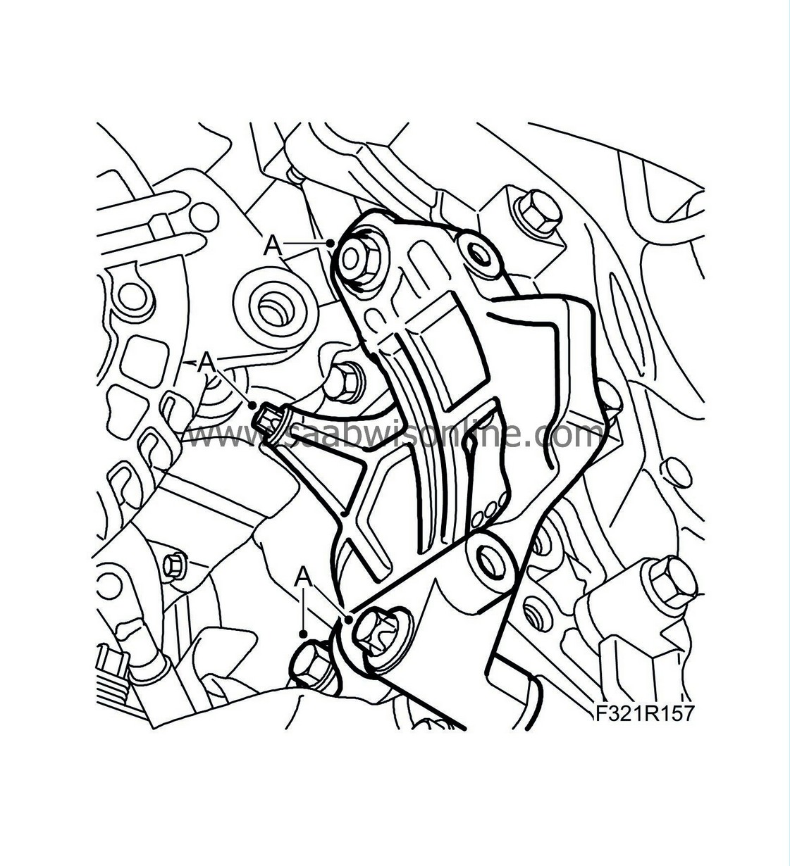
Remove the alternator bracket (A).
|
|
4.
|
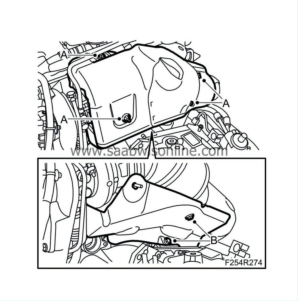
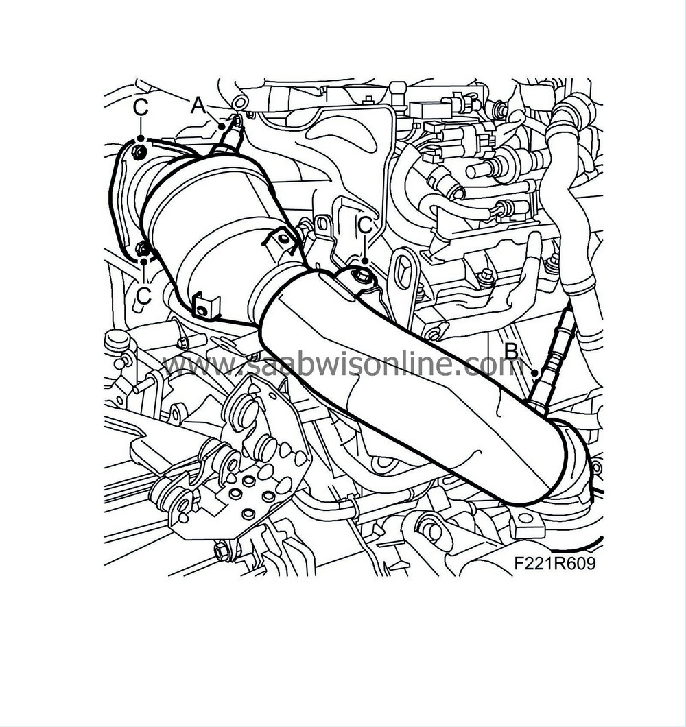
Remove the heat shield from the turbocharger A(A) and catalytic converter (B).
|
|
5.
|
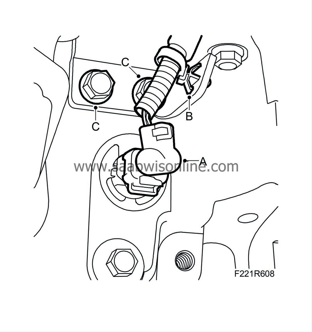
Unplug the oil level sensor connector (A) and undo its clips (B).
|
|
6.
|
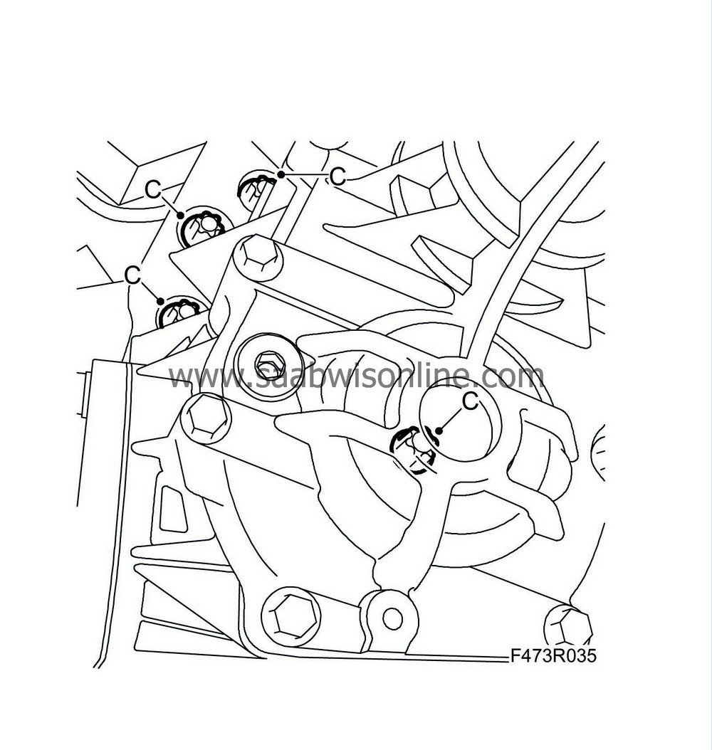
Remove the bolts (C) of the catalytic converter's lower bracket.
|
|
7.
|
Unplug the connectors of the heated oxygen sensors.
|
|
8.
|
Detach the upper oxygen sensor (A) and the lower (B) one from the catalytic converter.
|
|
9.
|
Remove the catalytic converter with bracket (C).
|
|
10.
|
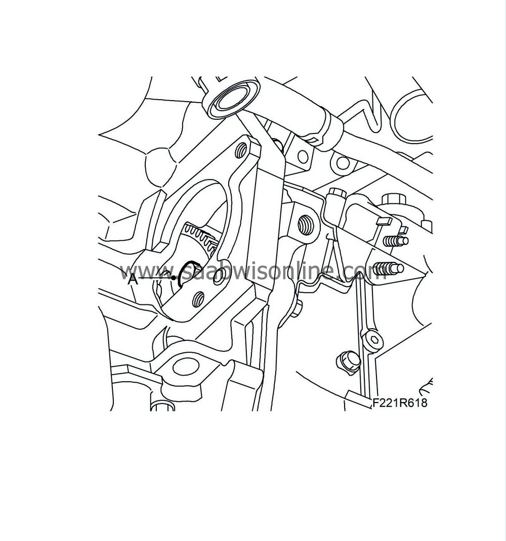
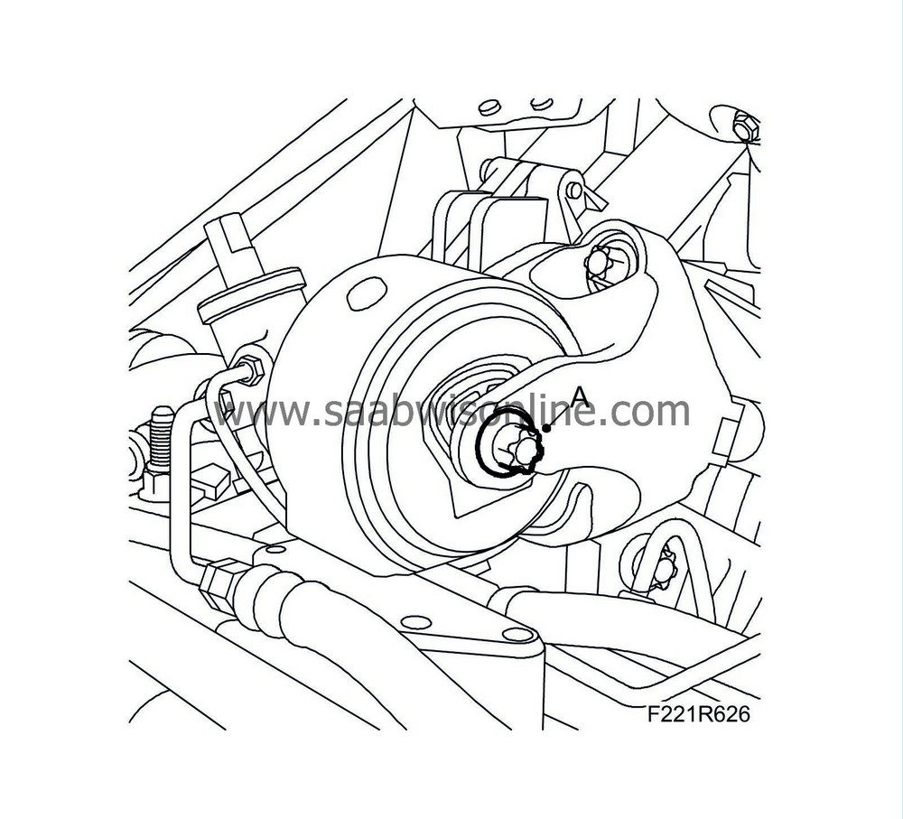
Tap the drive shaft (A) out of the transfer case using a brass drift and mallet. Have a second mechanic help to keep the drive shaft horizontal.
 Warning
|
|
Use protective goggles to protect against flying splinters of metal.
|
|
|
|
|
|
|
|
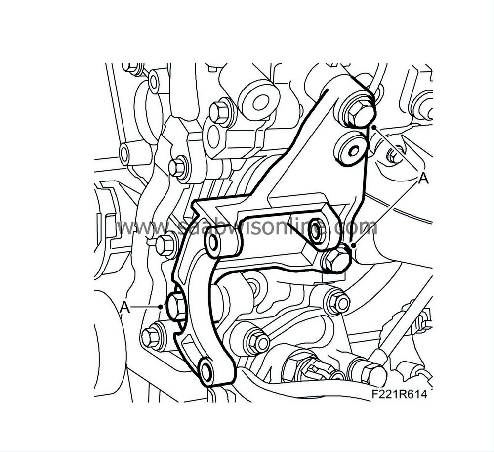
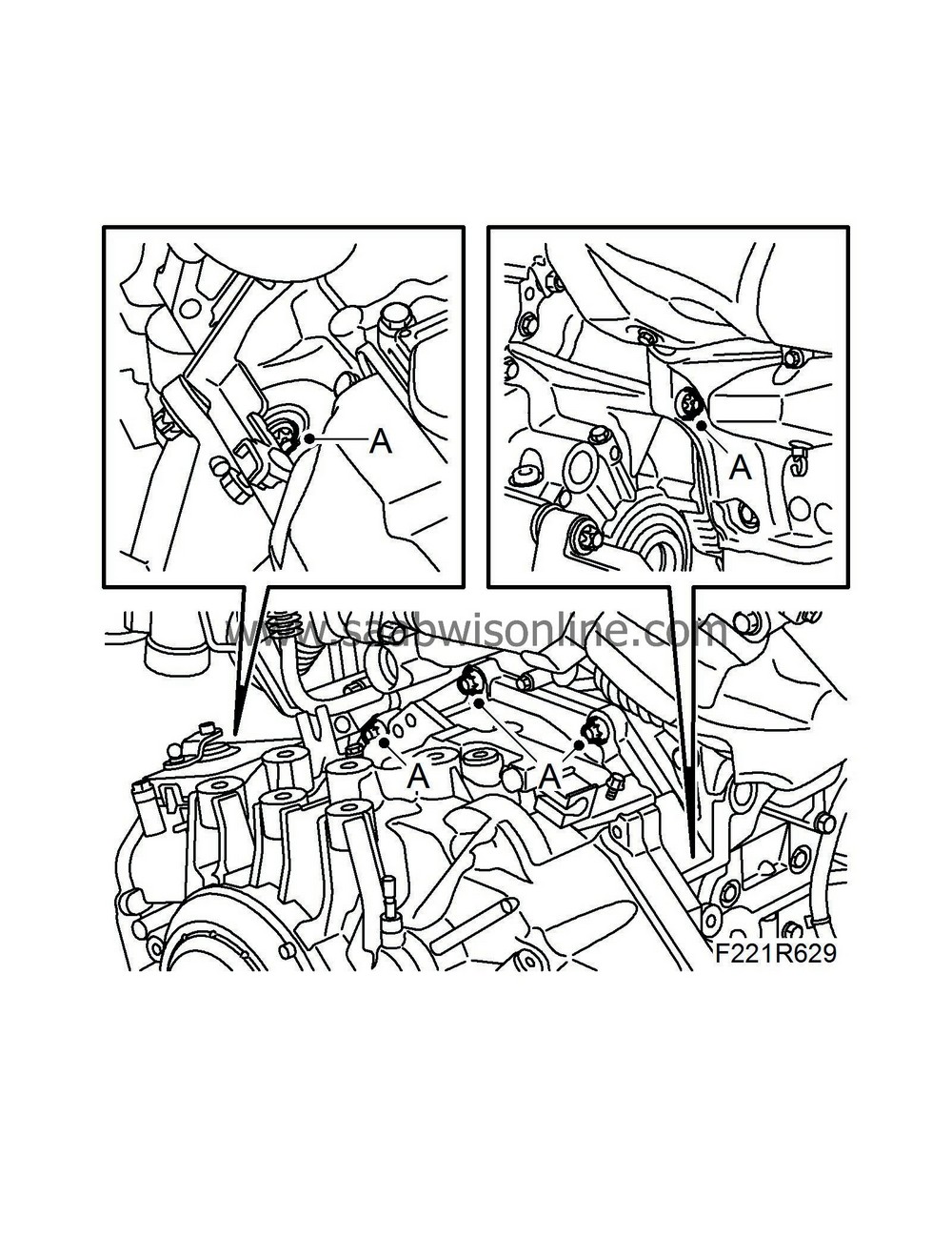
11.
|
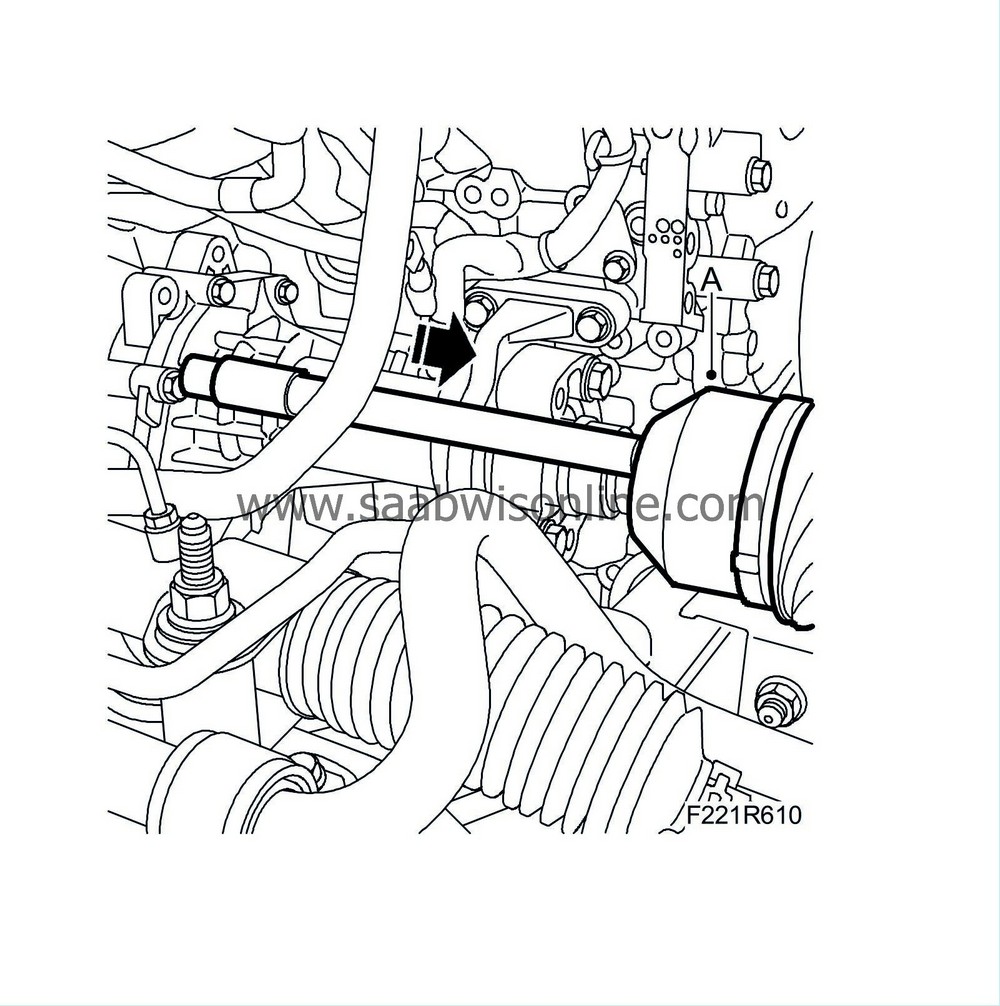
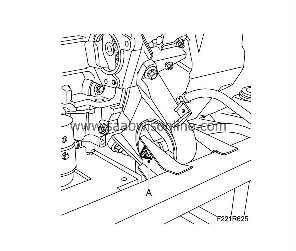
Remove the engine mounting (A) from the engine.
|
|
12.
|
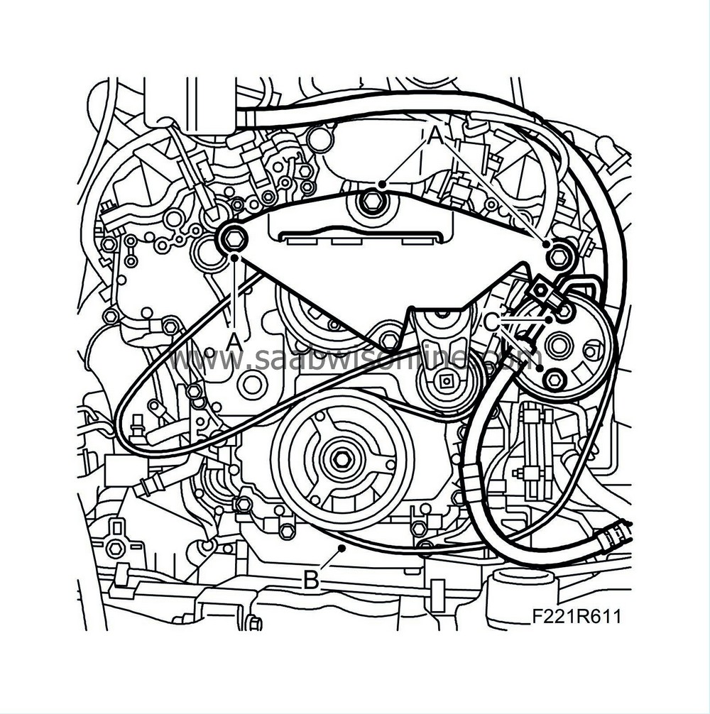
Remove the drive belt (B).
|
|
13.
|
Remove the power steering pump (C). Let the servo hoses remain on the pump.
|
|
14.
|
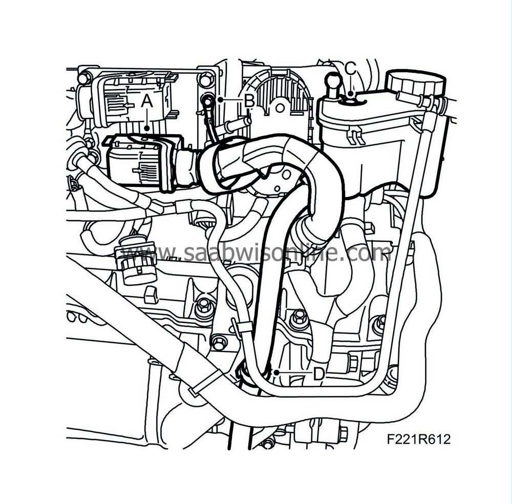
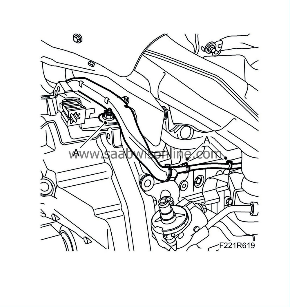
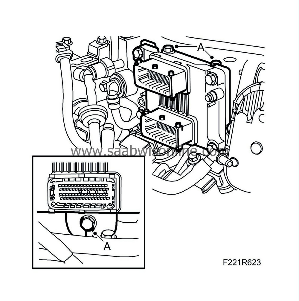
Unplug the control module connector (A) and disconnect the ground cable (B).
|
|
15.
|
Remove the power steering fluid reservoir (C) and the servo hose clips (D).
|
|
16.
|
Remove the A/C bracket and the turbocharger delivery pipe bracket (A).

|
|
17.
|
Remove the power steering pump bracket (A).
|
|
18.
|
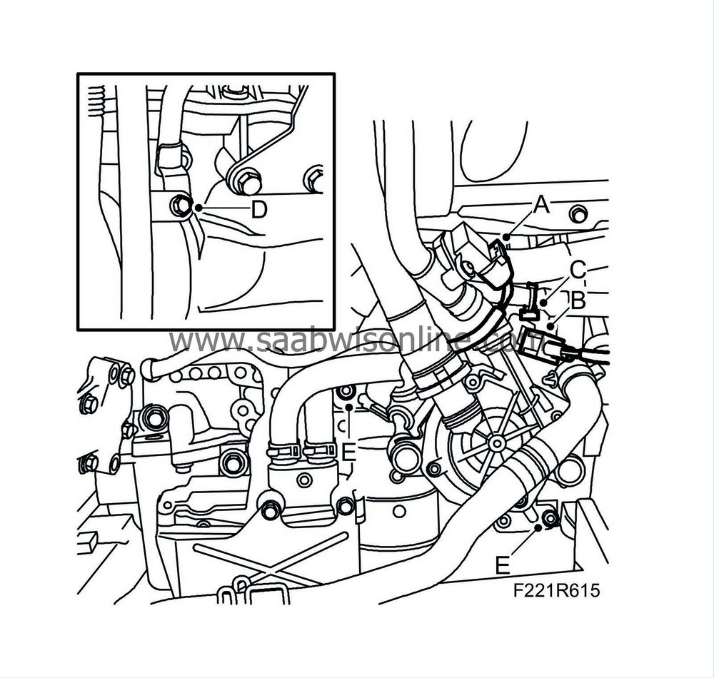
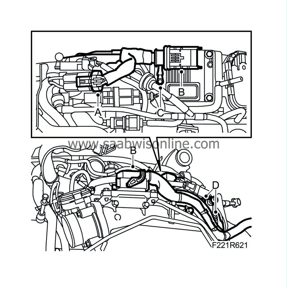
Remove the secondary air injection pump:
|
|
|
•
|
Unplug the sensor connector (A).
|
|
|
•
|
Unplug the secondary air pump connector (B).
|
|
|
•
|
Remove the breather pipe bolt (D).
|
|
|
•
|
Secondary air pump bolts (E).
|
|
19.
|
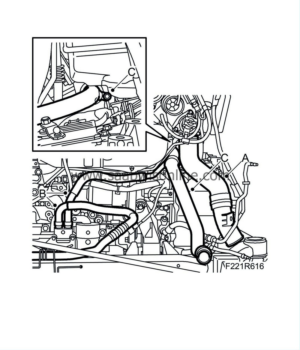
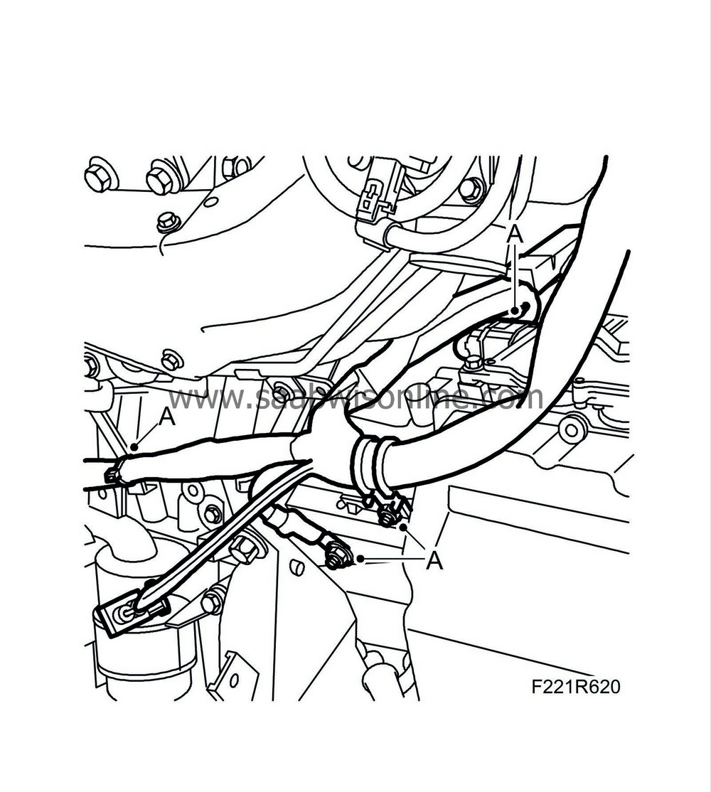
Detach the turbo delivery hose (A) from the turbo.
|
|
20.
|
Detach the coolant hoses (B) from the oil cooler. Collect any coolant spill.
|
|
21.
|
Detach the coolant pipe (D) with hoses from the thermostat housing.
|
|
22.
|
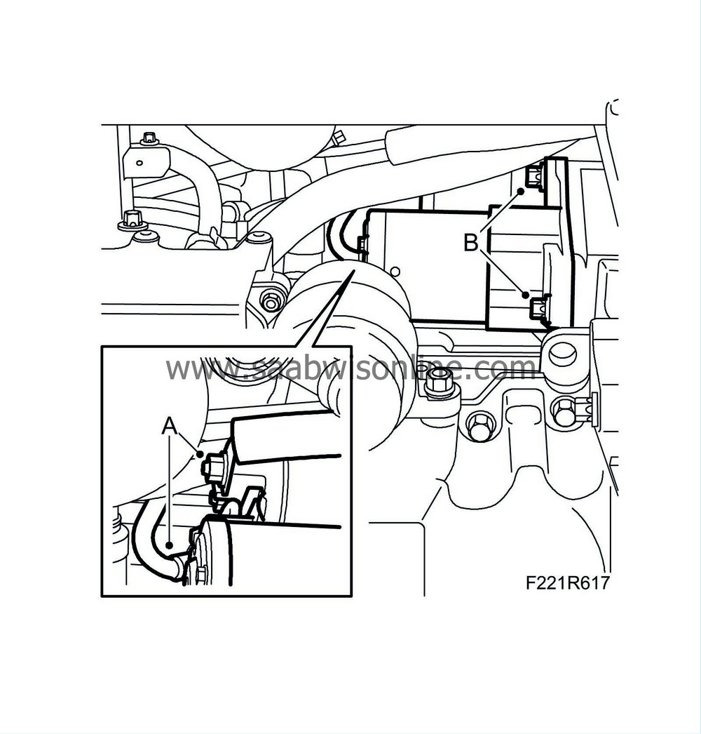
Disconnect the electrical connections of the starter motor (A).
|
|
23.
|
Remove the starter motor bolts (B).
|
|
24.
|
Aut:
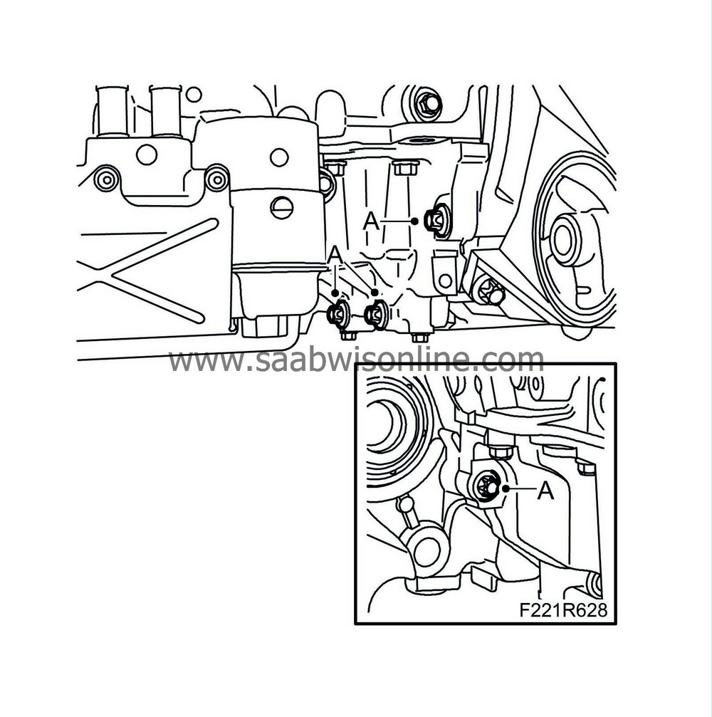
Remove the bolts (A) holding the torque converter in place.
|
|
25.
|
Remove the wiring harness (A) between the starter motor and generator as well as the one from the rear of the intake manifold. Release the two clips from the back of the engine and the cable duct on the gearbox.
Man:
Remove the cable mounting from the gearbox and unplug the reversing light switch connector.
Aut:
Remove the clamp and ground cable from the plate bracket and unplug the connector from the gear selector position sensor/control module.
|
|
26.
|
Disconnect the 7-pin connector (A), the control module connector (B), the ground cable (C) and the cable duct (D) from the intake pipe. Lift away the wiring harness.
|
|
27.
|
Remove the engine guard (A) with bracket.
|
|
28.
|
Remove the coolant pipe (A) between the heat exchanger and thermostat housing.
|
|
30.
|
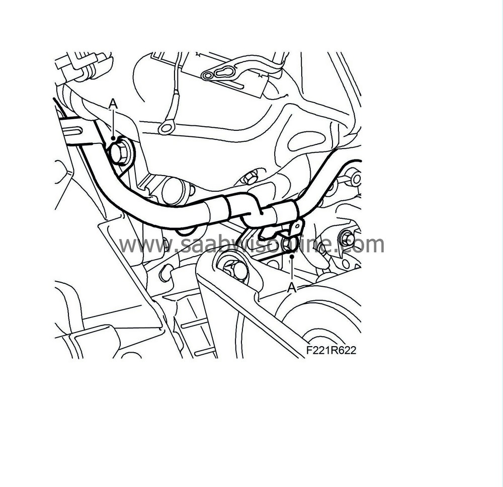
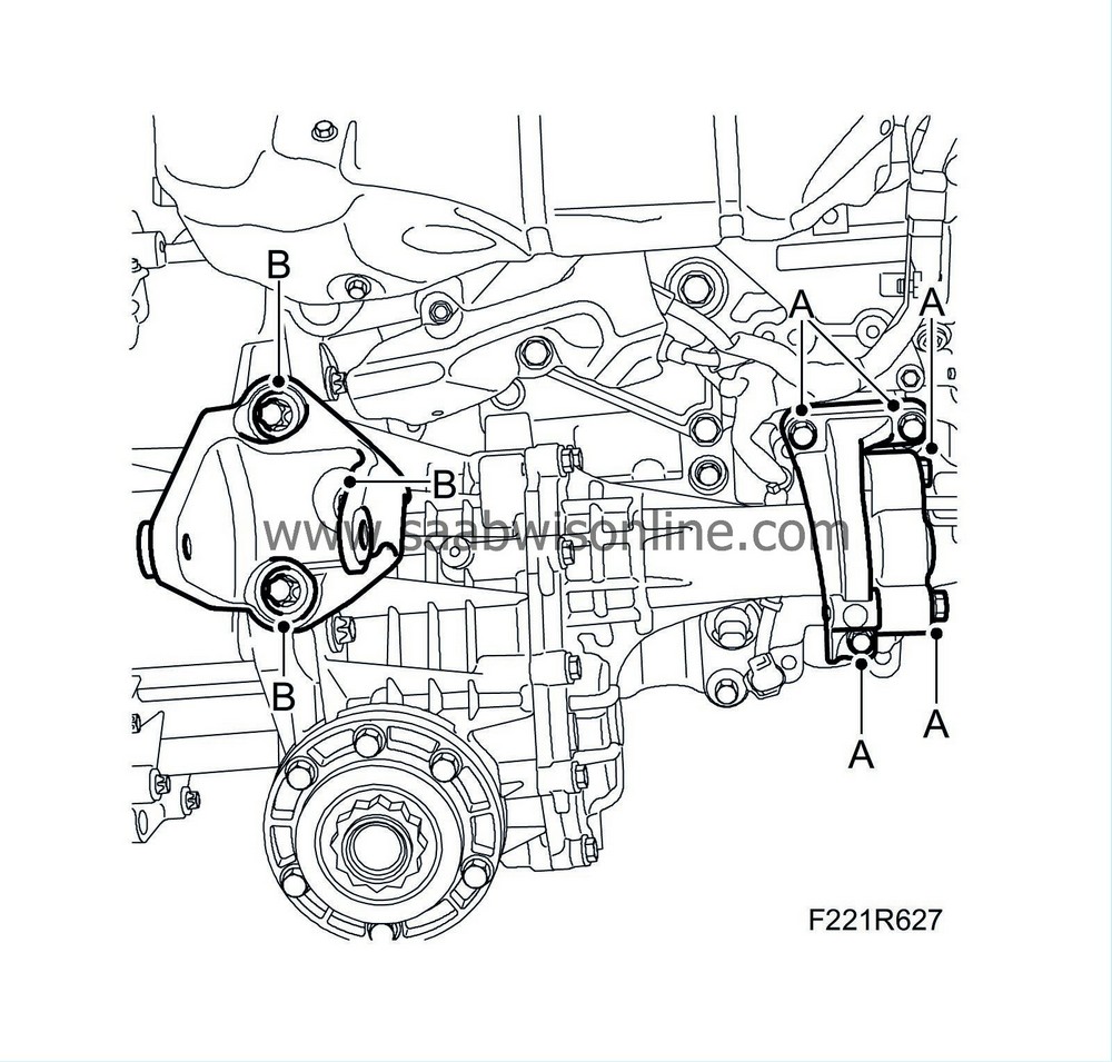
Remove the bolts (A) holding the torque arms to the subframe.
|
|
31.
|
Raise the engine from the subframe.
|
|
32.
|
Remove the support bracket (A) from the transfer case.
|
|
33.
|
Remove the rear torque arm bracket (B).
|
|
34.
|
Remove the transfer case (C).
|
|
35.
|
Remove the lower bolts of the gearbox (A).
|
|
36.
|
Place the engine on the floor.
|
|
37.
|
Remove the upper bolts of the gearbox (A) and lift away the gearbox.
Aut:
Press the torque converter towards the gearbox.
|
|
39.
|
Transfer the crankcase ventilation hose.
|
|
Note
|
|
Read the engine designation (L or E) and the serial number on the old engine and stamp in the equivalent on the new one.
|
|
1.
|
Aut:
Turn the torque converter so that the bolt holes align with the holes on the driver plate and turn the engine so that the oval hole in the driver is centred at the starter motor opening. Fit
87 92 574 Holder
to hold the torque converter in place during fitting. Lubricate the torque converter guide pin with grease.
|
|
2.
|
Make sure the two guide sleeves are fitted on the engine and apply grease to the guide sleeves.
|
|
3.
|
Fit the gearbox to the engine.
Aut:
Remove 87 92 574 Holder just before the gearbox is in place.
|
|
4.
|
Tighten the upper bolts between the engine and gearbox (A).
Aut:
Fit the plate bracket for the ground cable.
Tightening torque, M10 bolts, 40 Nm (30 lbf ft).
Tightening torque, M12 bolts, 70 Nm (52 lbf ft).
Tightening torque, other bolts, 19 Nm (14 lbf ft).
|
|
6.
|
Fit the lower bolts (A) between the engine and gearbox.
Tightening torque, M10 40 Nm (30 lbf ft)
Tightening torque, M12 70 Nm (52 lbf ft)
|
|
7.
|
Clean the mating faces between the transfer case and the gearbox.
|
|
8.
|
Raise and correctly position the transfer case against the gearbox.
|
|
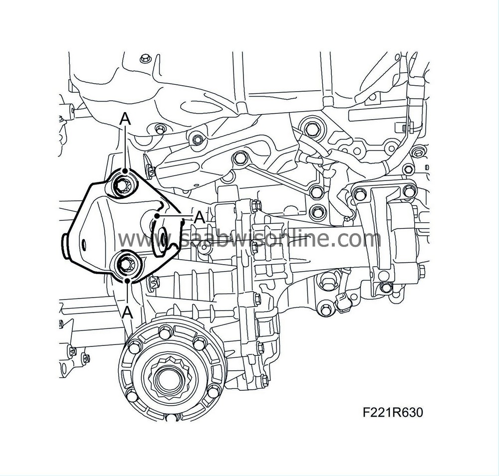
9.
|
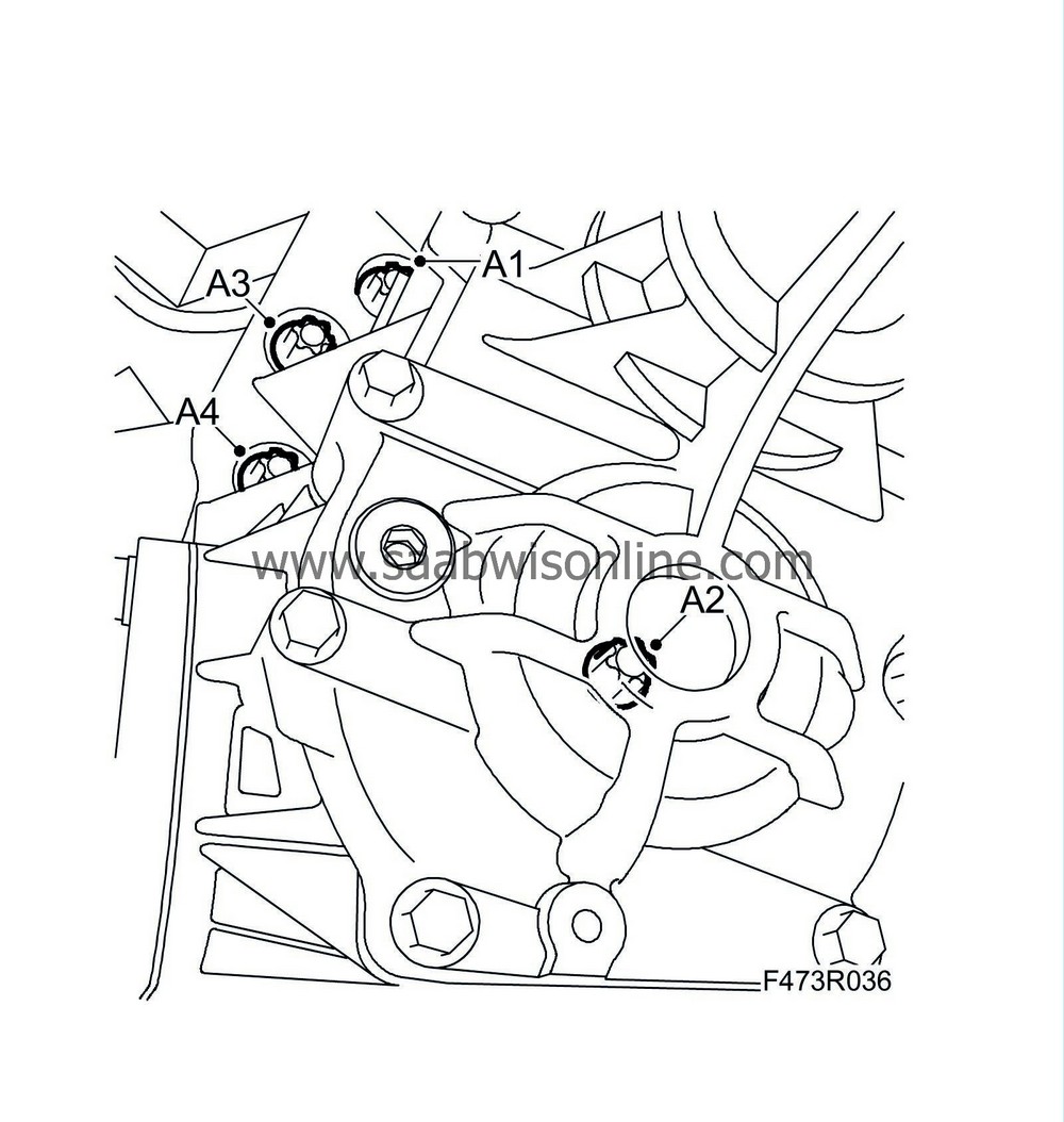
Fit the transfer case (A). Tighten the bolts in the illustrated order.
Tightening torque 110 Nm (81 lbf ft)
|
|
10.
|
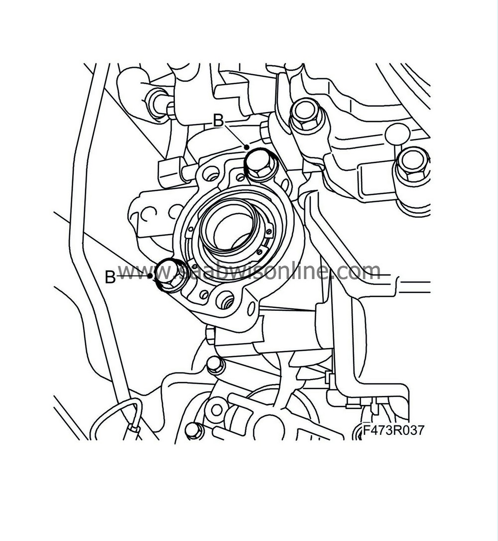
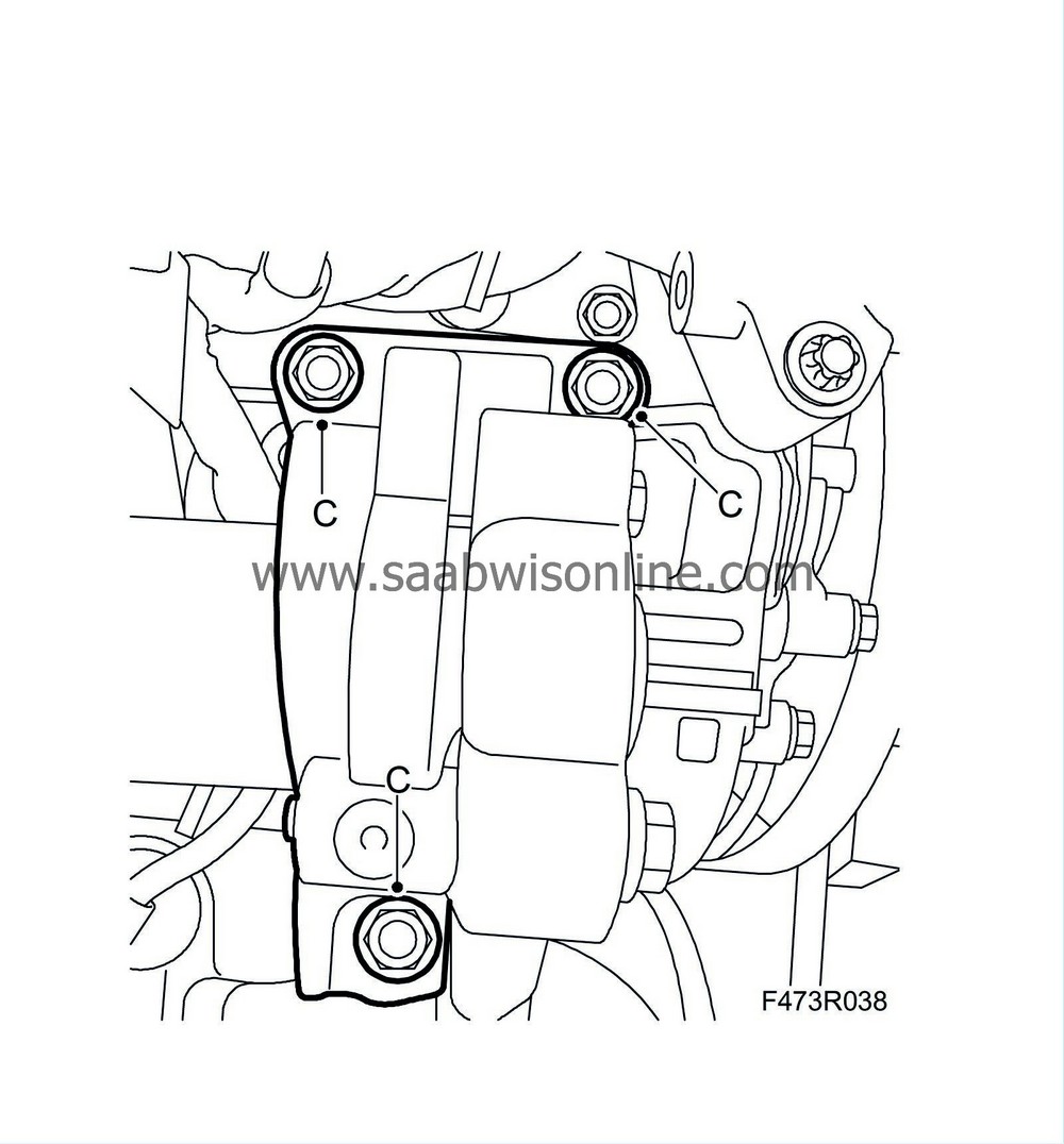
Fit the support bracket between the transfer case and the engine carefully in three stages to prevent ruptures.
Tightening torque (B), stage 1: 5 Nm (4 lbf ft).
Tightening torque (C), stage 2: 20 Nm (15 lbf ft)
Tightening torque (B), stage 3: 60 Nm (44 lbf ft).
|
|
11.
|
Fit the rear torque arm bracket (A).
Tightening torque 80 Nm (59 lbf ft).
|
|
12.
|
Fit the bolts that hold the torque arms to the subframe.
Tightening torque, rear torque arm: 80 Nm (59 lbf ft)
Tightening torque, front torque arm: 60 Nm + 90° (44 lbf ft + 90°)
|
|
13.
|
Aut:
Press the torque converter against the driver plate. Fit the plug.
|
|
14.
|
Aut
: Apply thread locking adhesive, Loctite 242, to the bolts holding the torque converter to the driver plate.
|
Note
|
|
Use the original bolts with corresponding washers. The torque converter will be ruined if the bolts that are used are too long.
|
|
|
15.
|
Aut
: Turn the crankshaft clockwise with the pulley and tighten the bolts (A) one at a time starting with the oval hole in the driver plate.
Tightening torque: 62 Nm (46 lbf ft)
|
|
16.
|
Fit the coolant pipe (A) between the heat exchanger and thermostat housing. Use a new O-ring coated with non-acidic Vaseline.
|
|
17.
|
Position the wiring harness.
|
|
18.
|
Fit the wiring harness (A) between the starter motor and generator as well as the one to the rear of the intake manifold. Fit the two clips to the back of the engine and the cable duct to the gearbox.
Man:
Fit the cable mounting to the gearbox and plug in the reversing light switch connector.
Aut:
Fit the clamp and ground cable to the plate bracket and plug in the connector of the gear selector position sensor/control module.
|
|
19.
|
Fit the engine guard (A) with bracket.
|
|
20.
|
Fit the 7-pin connector (A), control module connector (B), ground cable (C) and cable duct (D) to the intake pipe.
|
|
21.
|
Fit the starter motor bolts (B).
Tightening torque 47 Nm (35 lbf ft)
|
|
22.
|
Fit the electrical connections of the starter motor (A).
|
|
23.
|
Fit the coolant pipe (C) to the thermostat housing. Use a new O-ring coated with non-acidic Vaseline.
|
|
24.
|
Attach the coolant hoses (B) to the oil cooler.
|
|
25.
|
Fit the turbocharger delivery hose (A) to the turbo.
|
|
26.
|
Fit the secondary air injection pump:
|
|
|
•
|
Fit the bolts of the secondary air injection pump (E).
|
|
|
•
|
Fit the breather pipe bolt (D).
|
|
|
•
|
Plug in the secondary air pump connector (B).
|
|
|
•
|
Plug in the sensor connector (A).
|
|
27.
|
Fit the power steering pump bracket (A).
|
|
28.
|
Remove the A/C bracket and the upper bracket of the turbocharger delivery pipe (A).
Tightening torque, A/C bracket: 38 Nm (28 lbf ft)
|
|
29.
|
Fit the power steering fluid reservoir (C) and the servo hose clips (D).
|
|
30.
|
Plug in the control module connector (A) and connect the ground cable (B).
|
|
31.
|
Fit the power steering pump (C).
Tightening torque: 19 Nm (14 lbf ft)
|
|
32.
|
Fit the drive belt (B).
|
|
33.
|
Attach the engine mounting (A) to the engine.
Tightening torque 93 Nm (69 lbf ft)
|
|
34.
|
Attach the drive shaft (A) to the transfer case.
|
|
35.
|
Fit the catalytic converter with bracket (C). Apply 90 513 210 Universal paste to the nut threads.
Tightening torque, flange to turbocharger: 25 Nm (18 lbf ft)
|
|
36.
|
Apply a thin coat of 90 513 210 Universal paste to the oxygen sensor threads. Attach the upper (A) and lower (B) oxygen sensors to the catalytic converter.
Tightening torque 45 Nm (33 lbf ft).
|
|
37.
|
Plug in the connectors of the heated oxygen sensors.
|
|
38.
|
Fit the bolts (C) of the catalytic converter's lower bracket.
Tightening torque to oil sump: 23 Nm (17 lbf ft)
|
|
39.
|
Plug in the oil level sensor connector (A) and attach its clips (B).
|
|
40.
|
Fit the head shield to the catalytic converter (B) and turbocharger (A).
|
|
41.
|
Fit the alternator bracket (A).
Tightening torque, M8 22 Nm (16 lbf ft)
Tightening torque, M10 38 Nm (28 lbf ft)
|
|
42.
|
Fit the alternator retaining bolts (B).
Tightening torque 24 Nm (18 lbf ft).
|
|
43.
|
Connect the electrical connections of the alternator (A).
|


