PRE-RELEASE
Detailed description B284
| Detailed description B284 |
| Cylinder block |
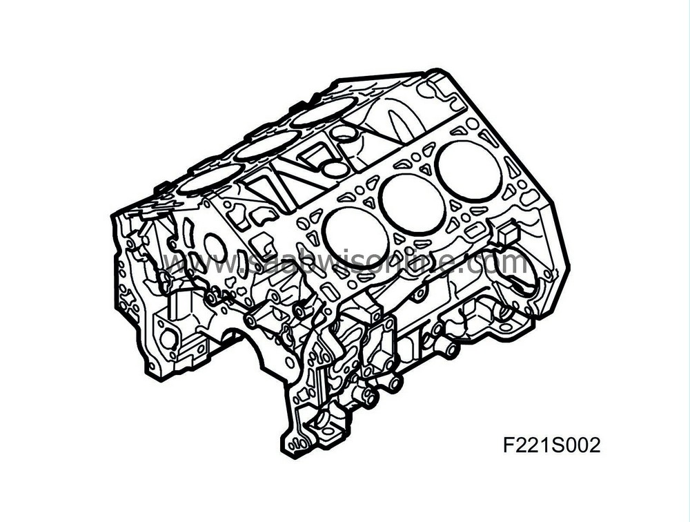
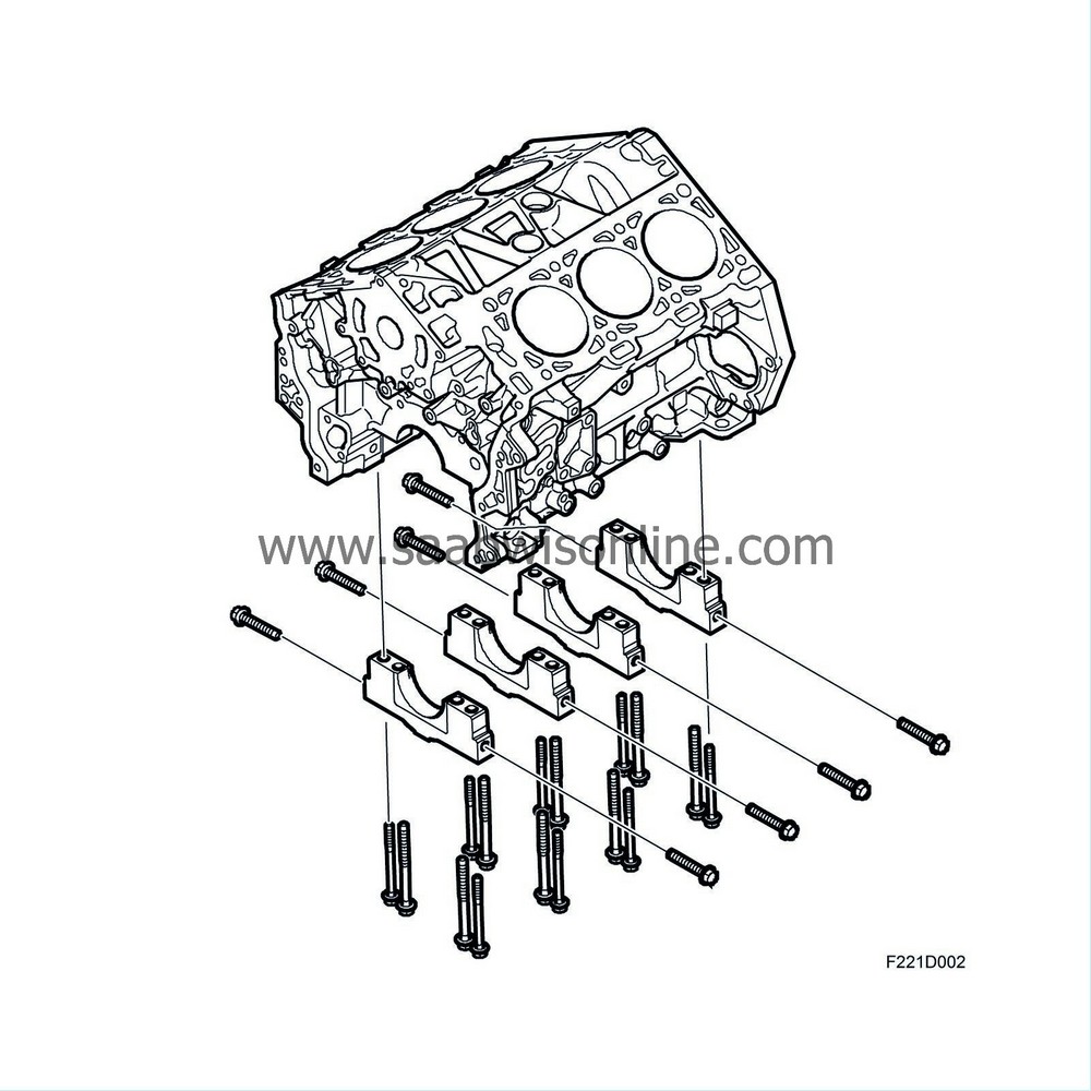
B284 is a fluid-cooled, 6-cylinder V engine made of an aluminium alloy. Then engine has a 60° angle between the cylinder banks, four valves per cylinder and two overhead camshafts per bank. The engine is a crossflow type, i.e. with intake ducts on one side and exhaust ducts on the other side of the combustion chambers. The cylinder liners are steel and are cast in the cylinder block. The cylinders are completely surrounded by coolant, including between the cylinders. The four main bearing caps are mounted with six bolts each. Two of the six bolts are so-called cross bolts, constituting an important part of the stability in the bottom of the cylinder block. The thrust bearing is located at the third main bearing cap.
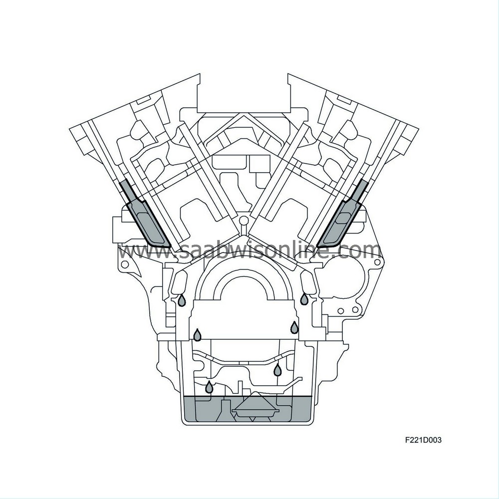
In order to reduce the amount of air mixed in the oil in the crankcase, return oil is led from the cylinder heads in ducts that lead to the oil sump. Thus, the return oil does not come in contact with moving parts such as the crankshaft and connecting rods.
The cylinder block also houses bored oil ducts to supply oil to bearings, the turbocharger and the cam phasing mechanism.
| Cylinder head |
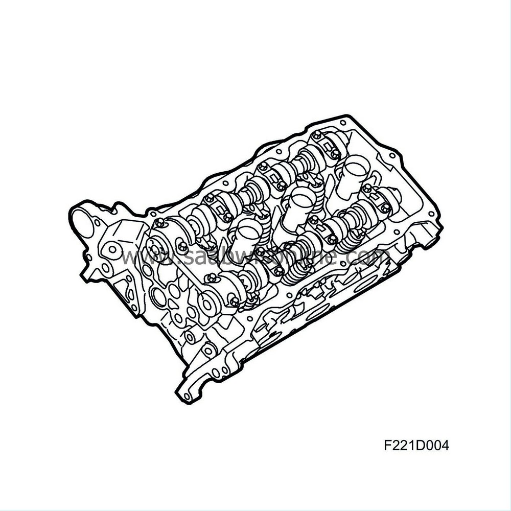
The cylinder head is made of aluminium and has four valves per cylinder. The combustion chambers are pentroof type. Two camshafts are mounted in the cylinder head with four bearing caps. The bearing cap closest to the camshaft sprocket has cast ducts for transferring oil to the CVCP pinion of the intake camshaft.
The cylinder heads also house a position sensor for the intake camshaft and valves for CVCP control.
| Crankshaft |
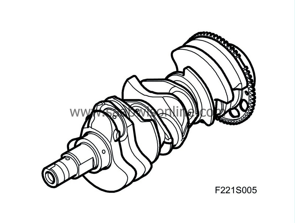
The crankshaft is made of forged steel and has ground bearing journals, the surface of which is hardened via induction hardening. This generates a hard outer layer that protects against wear. The crankshaft is mounted in four main bearings, no. 3 of which has a thrust bearing. The crankshaft contains bored ducts for lubrication oil. The crankshaft is dynamically balanced. It is relatively compact and powerful, which reduces torsional vibration and vibration. The toothed wheel of the the crankshaft position sensor is mounted on the rear edge of the crankshaft. It comprises a steel disc with 58 teeth and one space with no tooth.
| Piston |
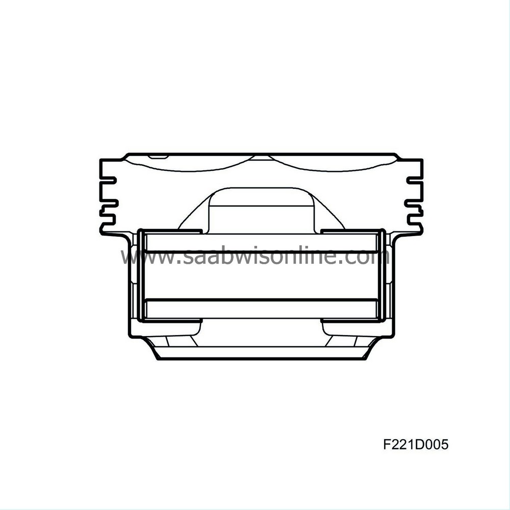
The pistons are made of a light metal alloy and have grooves for two compression rings and one groove for the oil scraper ring. The piston ring grooves are hard anodised to reduce wear. The top compression ring is made of stainless steel and has a plasma coating. The other compression ring is made of cast iron and is a napier ring. Both compression rings are low tension rings. The three-piece oil scraper ring comprises two thin, chromium-plated scraper rings with an expander between. The piston ring groove is drained via four slits - two on each side of the piston. The gudgeon pin is free floating in the piston.
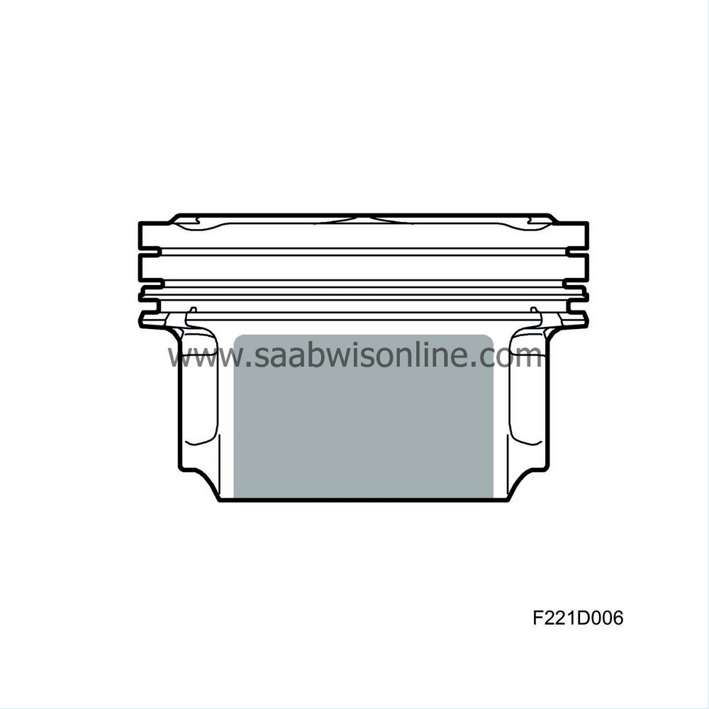
The piston skirts have a graphite coating in order to reduce wear and friction against the cylinder walls.
| Connecting rod |
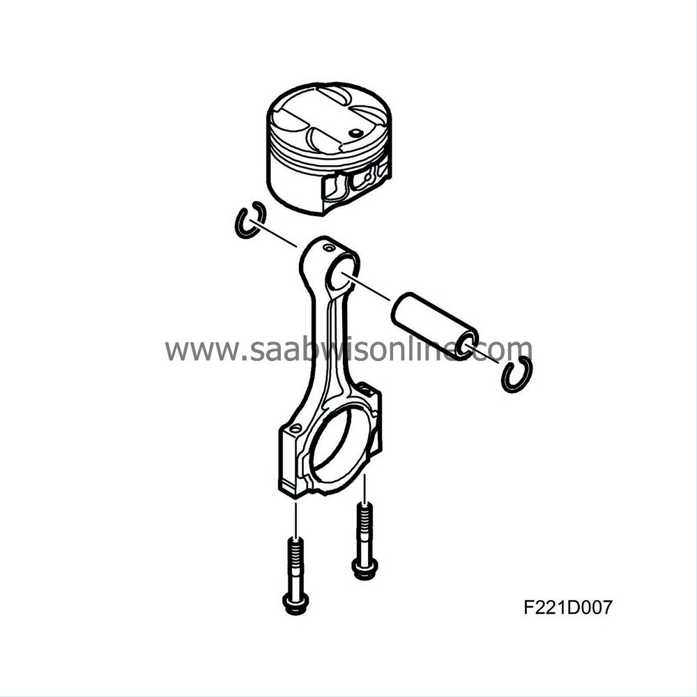
The connecting rods are made of sinter-forged steel. The principle behind such is that a steel alloy in powder form is poured into a form. The form is pressed together and heated. The metal powder that is pressed together and heated to its fusing point fuses into a strong yet light connecting rod.
The greatly dimensioned small end has a bearing bushing of brass while the big end has two loose bearing shells. The top of the small end contains a bored hole for lubrication. Both bearing bushings and the bearing shells can be replaced.
The big end bearing cap is divided by splitting, which generates good fit and roundness.
| Cam transmission |
The engine is equipped with four overhead camshafts - two per cylinder head. A gear wheel mounted on the cranksahft drives the so-called primary chain, which is toothed. A self-adjusting hydraulic chain tensioner ensures that the primary chain has the correct tension. The chain is controlled with the help of three chain control guides.
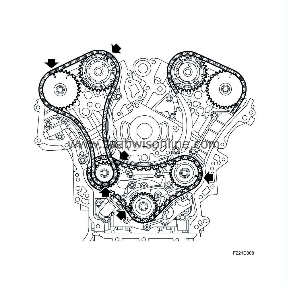
The distribution chain drive the distribution pinion of the front and rear bank's timing chains. A timing chain runs from the distribution pinion up to the respective cylinder head. Each timing chain has two guides and a self-adjusting hydraulic tensioner.
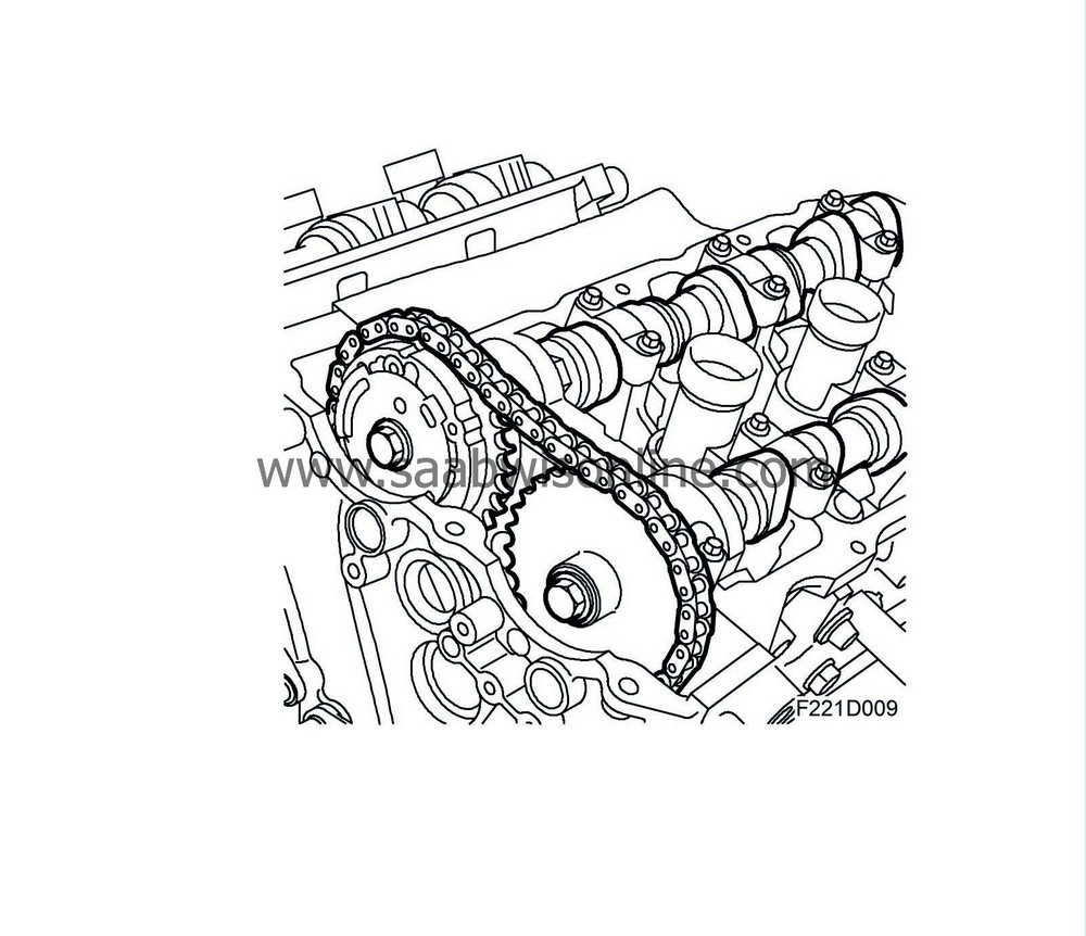
The exhaust camshaft has a silent pinion while the intake camshaft has a hydraulic cam phasing mechanism (CVCP). The camshafts actuate rocker arms with roller bearings (aka roller finger followers) that are shaped like a ball cup at one end. This ball cup meets the ball-shaped upper part of the hydraulic valve clearance balancer. The other end of the rocker arm actuates the valve stem. The hydraulic valve clearance balancers keep the clearance between the rocker arm /roller bearing at zero. The valve clearance balancers thus do not participate in the movement of the valve mechanism.
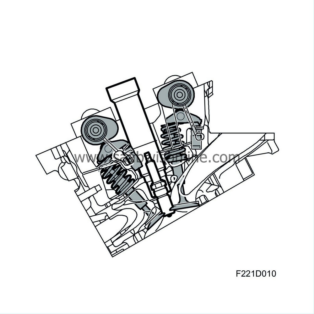
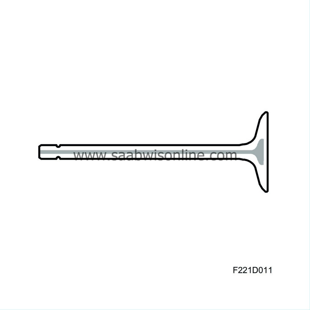
The valves are steel with chromium-plated spindles. The exhaust valves are sodium cooled.
| CVCP |
CVCP, general
Continous variable cam phasing (CVCP) is a system that makes continual variation of the intake camshafts' position, i.e. phasing, possible. The duration (the number of degrees the values are hold open) remains constant. It is the position of the cam lobes, i.e. the camshaft angles when the intake values open or close, that are different. This is controlled by ECM via hydraulic valves in order to obtain the optimal intake camshaft setting at any given operating point.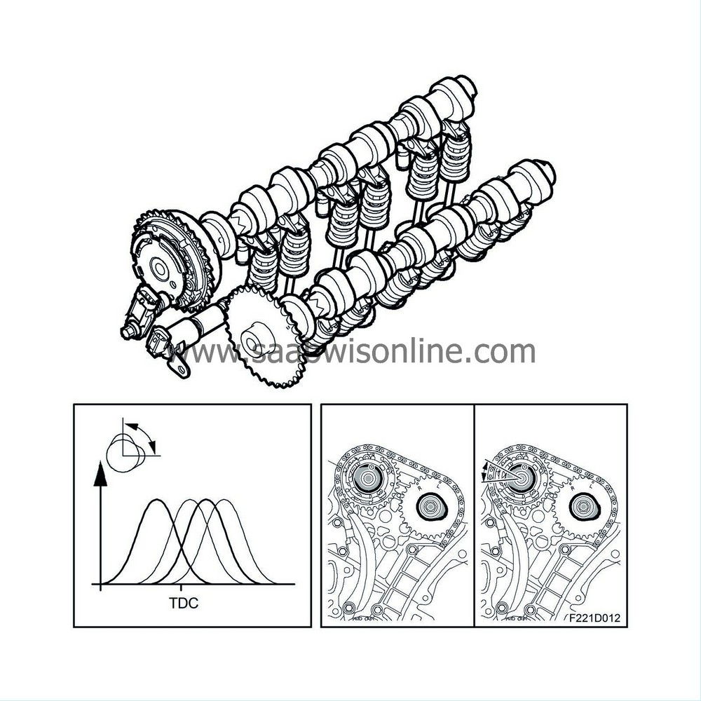
Camshaft, general
The camshafts control the movements of the valves. The profile of the camshaft lobes is determined by which properties were prioritised for the engine type in question. Normally, there are many conflicting requirements that must be met. High peak output often leads to uneasy idling and a weak low rpm register. On the other hand, if good low rpm properties are prioritised, high peak output suffers.Use of supercharging with a turbocharger makes it possible to make design limits a little fuzzy. You can choose a camshaft with good properties during idling and in the low rpm register. In the high rpm register, where the camshaft is a limitation, you can chan allow boost pressure to increase in order to compensate for the output the engine loses due to the mild camshaft profile.
Following this line of argument, fixed camshaft times are a limitation. With stricter environmental requirements and increased demands for soft engine running and high output, it is becoming increasingly difficult to get these conflicting requirements to come together. The solution is variable cam phasing. By equipping the intake camshafts with a pinion containing a hydraulic mechanism, the intake camshafts can assume the position most beneficial to the specific operating point.
Camshaft, idling
When idling, the camshaft is let go later, which reduces the overlap between the exhaust phase and intake phase. When the engine is idling, pressure in the intake manifold is low (vacuum). If the camshafts have a large overlap, i.e. the exhaust valves and intake valves are wide open at the same time, exhaust gases are sucked into the cylinder due to the negative pressure in the intake manifold. This results in a high residual gas content in the cylinder, which in turn leads to uneven idling and increased emissions. Note that at a slightly higher engine load, the engine can tolerate a higher residual gas content without uneven running. This is used to reduce emissions and fuel consumption.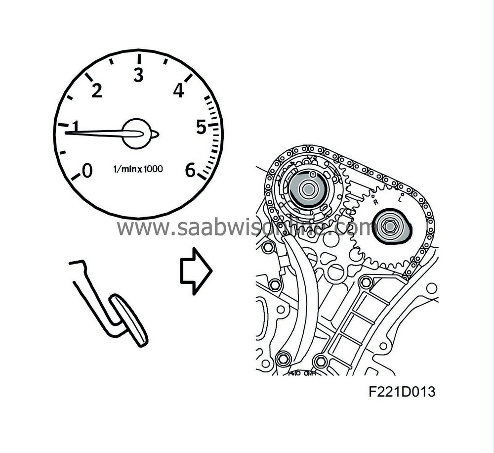
Camshaft, moderate load
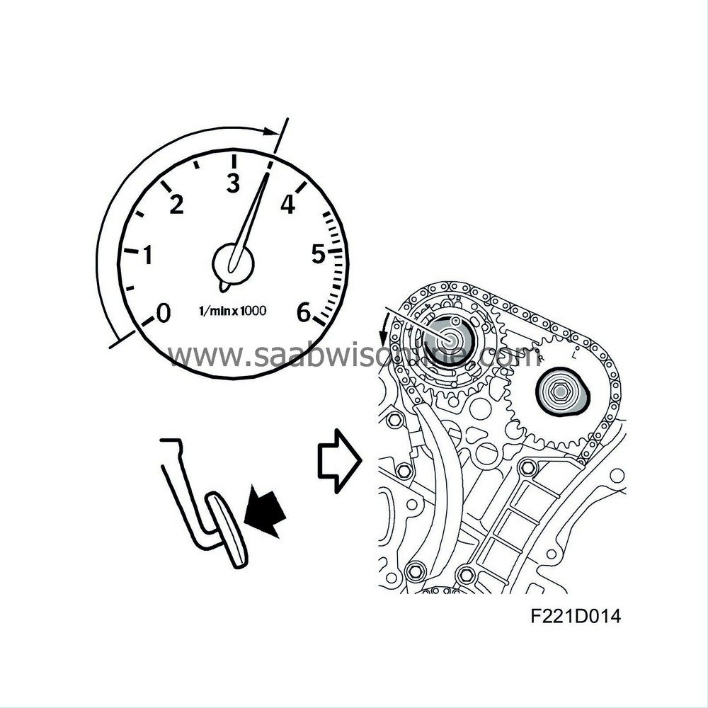
In order to reduce both exhast emissions, especially NOx and CO2, as well as fuel consumption, the intake camshafts are set rather early when engine load is moderate, corresponding to the load of the most common driving conditions, such as motorway driving. The purpose is to increase internal EGR. By increasing overlap, the residual gas content in the cylinders increases. The increased residual gas serve as a standard EGR system - adding exhaust gases to the charge air reduces the NOx content of the exhaust gases.Increased internal EGR also reduces pump loses during the engine intake phase. Pump loses are the work used for engine gas exchange. For example, when driving with a light load, the engine's air supply must be choked using the throttle valve. The pressure in the intake manifold is then low (vacuum). Because of this low pressure, the piston needs more energy to move down during the intake phase. If it is possible to increase pressure in the intake manifold without increasing the intake air mass (which would generate the wrong torque), pump loses would be reduced. In this case, the cylinders would be partially filled with residual gases, which would cause the pressure in the intake manifold to increase in order to take in the same air mass as would be required if there was not a high residual gas content.
Camshaft, high engine speed and high load
When the engine is running with a high load at a high engine speed, the capacity is increased in that the intake camshafts are allowed to go later. By filling the cylinder when the piston is down low (creating a large volume), there is room for more air mass at the same given intake pressure. Since engine speed is high, there is minimal backflow of air when the piston is on its way up in the cylinder even through the intake valves are open.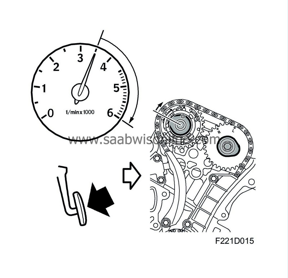
CVCP mechanism
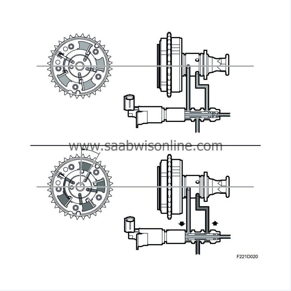
The CVCP mechanism consists of a housing with a gear for the timing chain. The walls on the inside of the housing contain four chambers. A rotor with four wings is situated in the centre of the housing and is mounted on the camshaft. A guide pin ensures correct positioning between CVCP and the camshaft during installation. Oil is led from the CVCP solenoid valve through ducts up to the camshaft bearing cap. A number of radial holes bored into the camshaft bearing surface lead oil in the camshaft to the CVCP mechanism's rotor and into the chambers.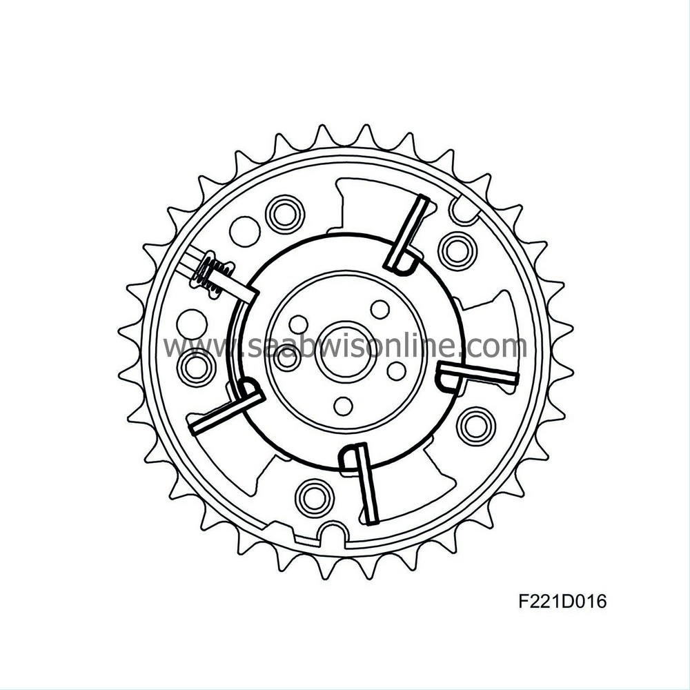
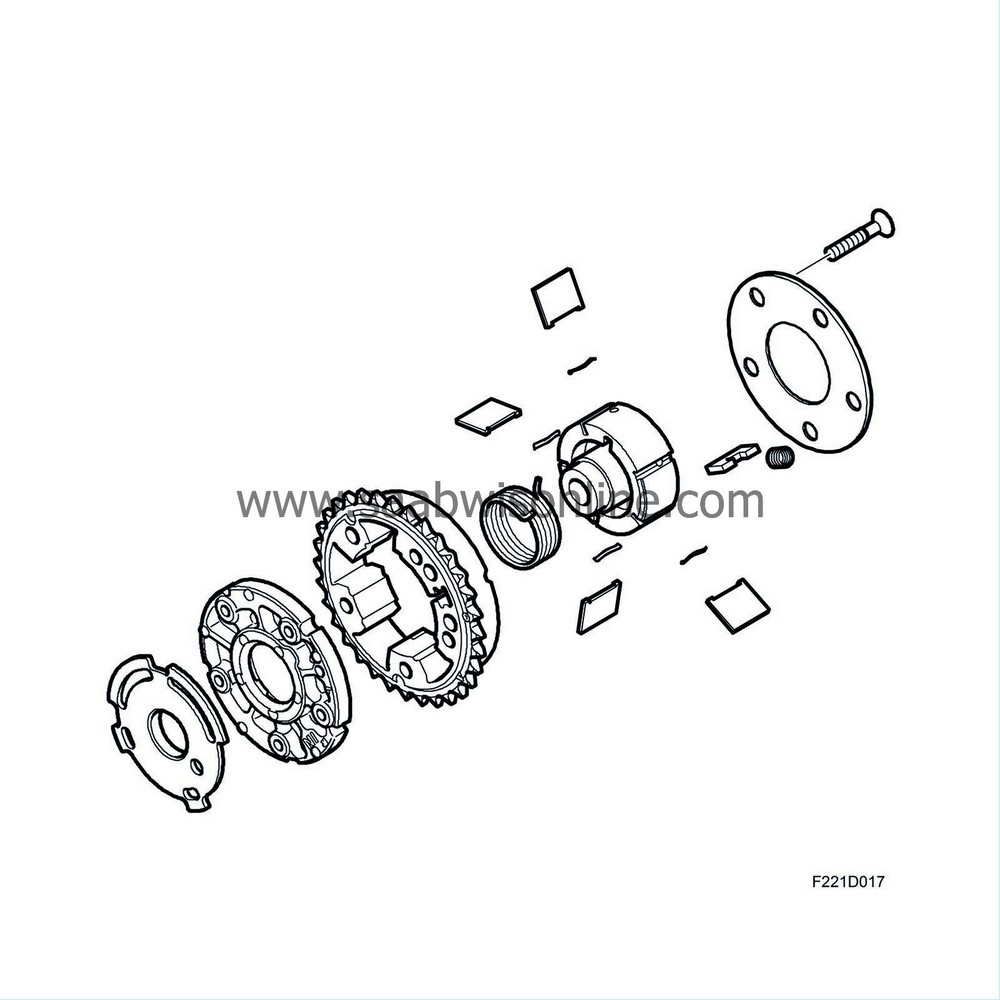
Regulation of oil flow affects the position of the wings in the chambers. The rotor (camshaft) position can thus be displaced in relation to the housing (timing chain). This way, the camshaft position can be displaced 50 crankshaft degrees. An aperture disc is mounted to the side of the rotor to enable ECM to measure the position of the camshaft.
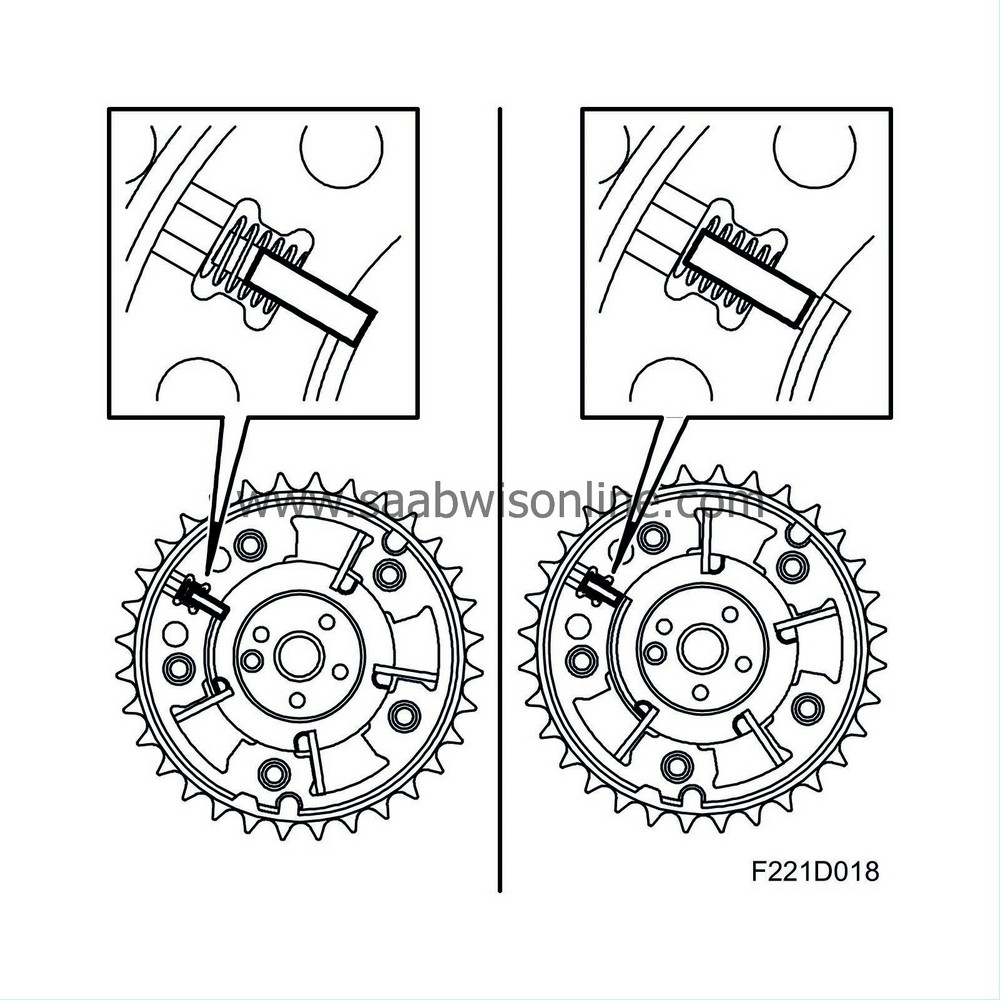
In order to ensure the camshaft position upon start and in the event of a system fault, the CVCP mechanism is equipped with a lock consisting of a spring-loaded pistong actuated by oil pressure to the "pre-setting side". Upon start or, for example, in the event of an open circuit on the lead to the solenoid valve, pressure on the pre-setting side becomes zero. The pistons locks the housing with the rotor and the camshaft position is now in the starting position. When the engine is then started and camshaft control begins to work, pressure on the pre-setting side increases and the spring force for the piston is overcome. Locking is released and the oil pressure actuates the wings in the chambers to turn the CVCP mechanism.
ECM regulates a PWM voltage to the solenoid valve, causing the valve plunger to move. The position of the plunger is determined by the balance between the return spring and the power from the coil. When the coil is de-energised, the plunger resumes its home position through the force of the return spring. The valve closes the oil flow to "pre-setting" and opens it to "post-setting". The CVCP mechanism then assumes its starting position.
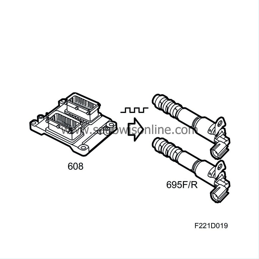
The valves have four ports, three of which have filters. The return port does not need a filter. The oil pressure from the engine's lubrication oil pump is supplied to the centre port. The plunger assumes different positions depending on the size of the PWM voltage. When no voltage is supplied, there is a connection between oil pressure and "post-setting". The port for "pre-setting" is connected to "oil return". By varying the PWM voltage, the plunger can assume any number of positions in order to achieve the desired camshaft setting.
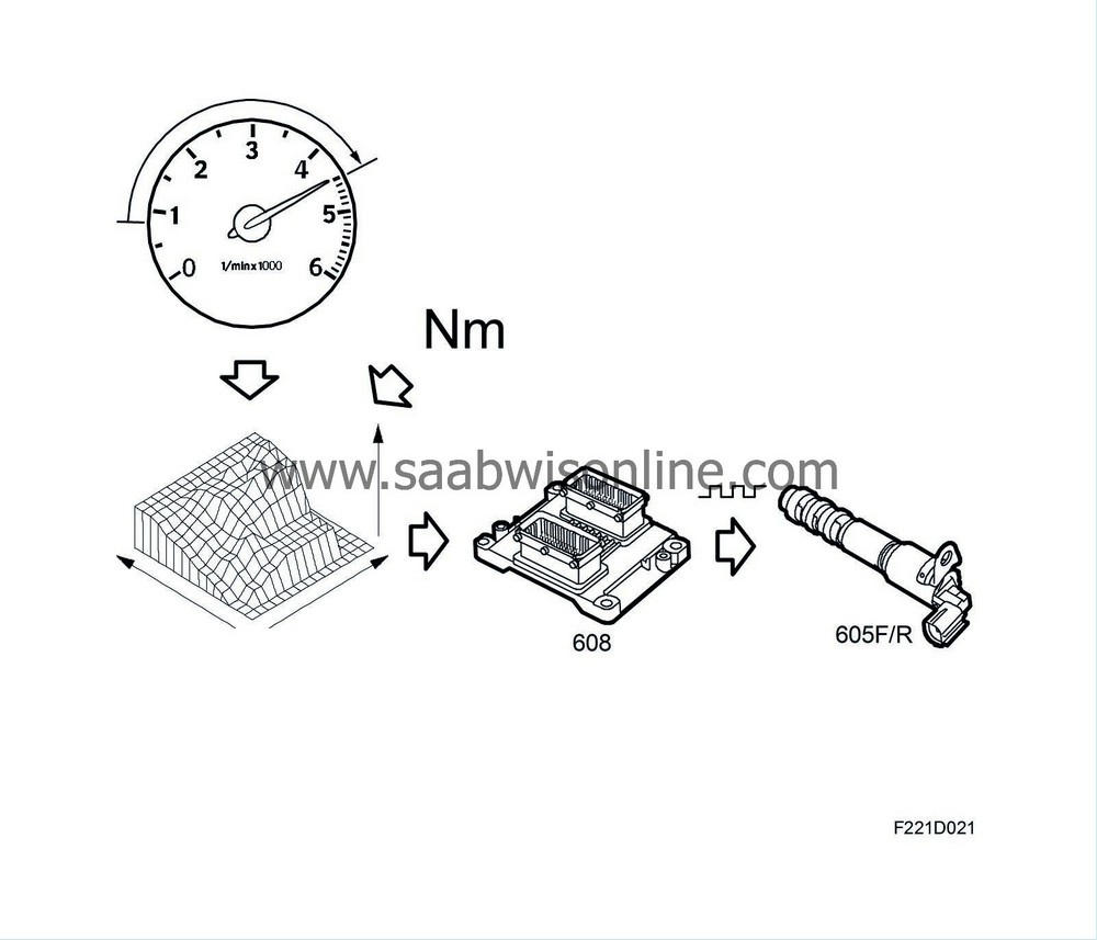
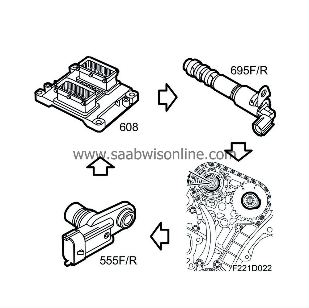
ECM regulates camshaft position based primarily on engine speed and load. A number of other values are used for minor compensations. Based on these values, ECM calculates requested camshaft position, converts it to the necessary PWM and sends it out to the valves. A Hall sensor reads the position of the aperture discs and thereby the current position of the camshafts. ECM compares the requested and actual positions. If there is deviation, the PWM voltage to the valves is corrected.
| Lubricating system |
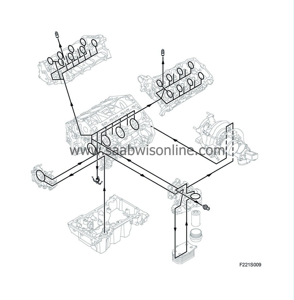
General
Engine oil is used not only to lubricate and cool the engine, but also for the operation of the CVCP mechanism. The oil sump is made of cast aluminium and has a lower and an upper baffle plate, a so-called windage tray. The oil level switch is mounted in the sump. The oil pump is a complete unit mounted in the cylinder block behind the cam timing cover. The oil cooler is mounted on the cylinder block while the front of the engine houses the filter housing and oil pressure switch.It is vital that the oil change intervals specified in the Saab Service Programme are followed to ensure that all engine components reach their full service life and that engine performance is optimal. Servicing must be carried out when one of the criteria - service message, distance or time - is met. It is also vital that oil complying with specification GM-LL-A-025 is used.

Oil sump
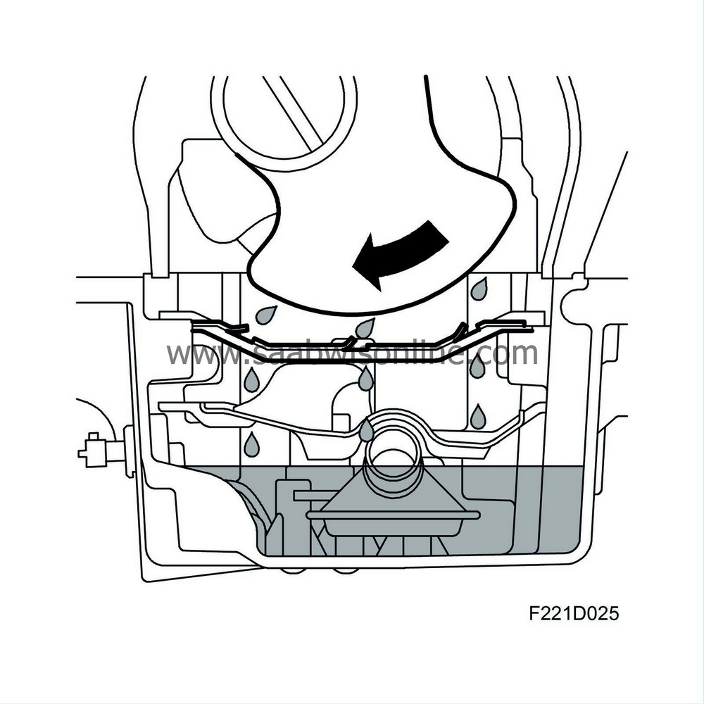
The oil sump is cast of an aluminium allow in a power version that reduces noise. The sump has a lower baffle plate to control oil movements and prevent the oil pump from sucking in air. To reduce crankshaft friction loses, the sump is also equipped with an upper baffle plate, a so-called "windage tray". This plate reduces the amount of oil drawn in with the crankshaft rotations, which in turn reduces friction. A oil level switch is mounted in the oil sump.
Oil pump
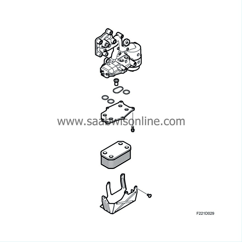
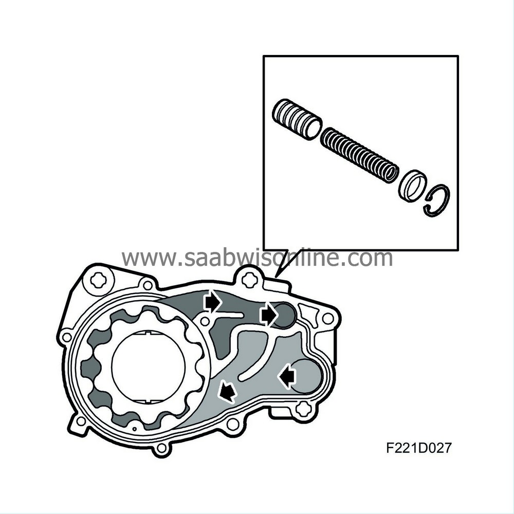
Engine lubrication is handled by a pressure lubricating system in which oil pressure is generated by a gear pump (a gerotor pump) consisting of a pump housing with cover, gear and a centrally displaced gear ring. The pump housing is mounted in the cylinder block behing the cam timing cover and is driven directly by the crankshaft. The pressure relief valve is located in the pump housing. The oil pump sucks in oil from the sump via a pipe. The oil is lead in the gear pump and is then forced out via a duct in the engine to the heat exchanger. Once the oil has passed the heat exchanger, it is filtered in the oil filter.
Oil filter
The engine is equipped with an oil filter order to prevent wear and engine damage from particles and to reduce engine wear. The filter is an insert filter. The filter cartridge should be changed as specified in the Service Programme. In the event of a filter clog, an overflow valve in the oil filter holder cover opens. The oil then passes without being cleaned. This is a safety feature since oil circulation is vital under all conditions.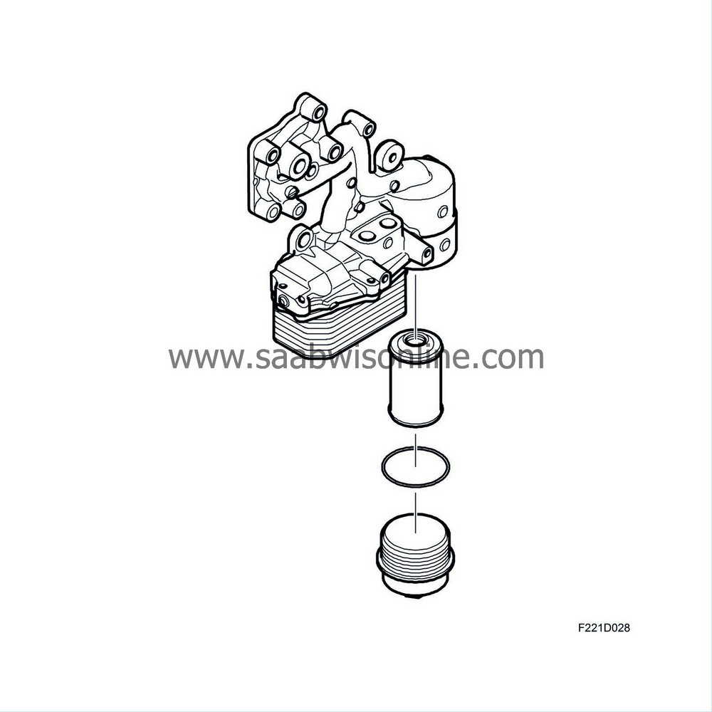
Heat exchanger
In order to maintain a uniform engine oil temperature, it passes through a heat exchanger. When a cold engine is started, the coolant warms up the engine oil. Conversely, if the engine is driven with a high load, i.e. the engine oil is warmer than the coolant, the heat exchanger cools the engine oil. The heat exchanger is mounted together with the oil filter on the cylinder block on the back of the engine.