PRE-RELEASE
Fuel injection
| Fuel injection |
| • |
Engine speed
|
|
| • |
Air mass
|
|
Through use of a wideband oxygen sensor, lambda control can be active even if the current lambda value deviates from 1.00. This is not possible with a conventional narrow band oxygen sensor.
Some advantages of continual lambda control with wideband sensor are:
| • |
Control of he current lambda value over the entire load/engine speed range. This provides improved emissions at full load.
|
|
| • |
Possibility to have the EVAP canister purge valve active throughout the entire load/engine speed range.
|
|
| • |
Improved ability to diagnose components such as the catalytic converter and AIR.
|
|
Lambda value
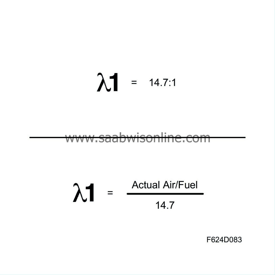
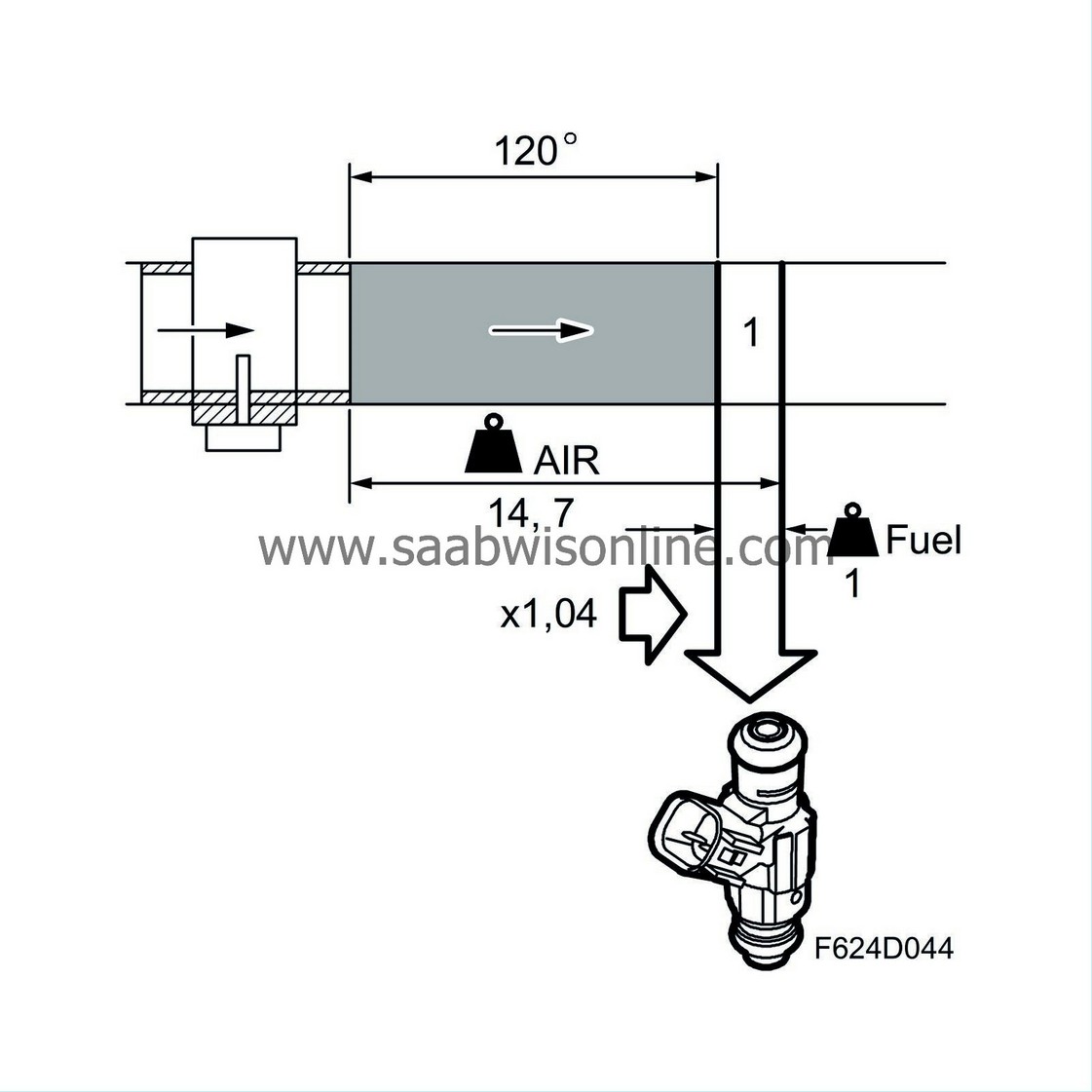
The lambda value describes the relationship between the actual mixture ratio and the mixture ratio for stoichiometric combustion (14.7:1 for petrol) Lambda = actual A/F / 14.7.
Example:
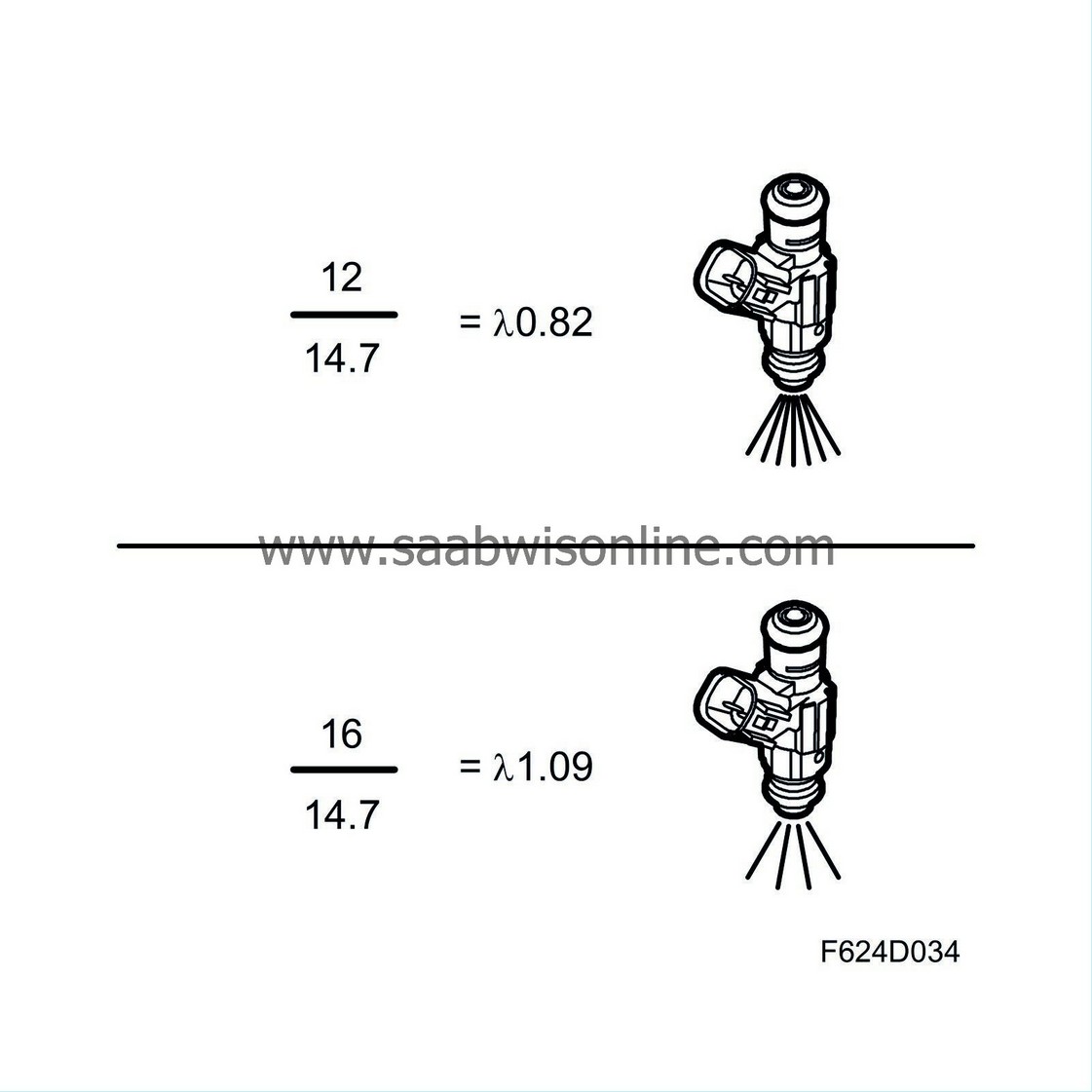
| • |
A mixture richer than stoichiometric, e.g. 12.0 parts air to 1 part fuel (12.0:1) generates a lambda value of 12.0/14.7 = 0.82.
|
|
| • |
A mixture leaner than stoichiometric, e.g. 16.0 parts air to 1 part fuel (16.0:1) generates a lambda value of 16.0/14.7 = 1.09.
|
|
The lambda value at idling speed is about 1.00 or a little less.
At high engine torque, the lambda value drops due to the extra fuel supplied via full load enrichment.
The lowest specific fuel consumption is obtained when the lambda value is between 1.10 and 1.20. The best output is obtained when lambda is 0.85-0.95. Neither of these is optimal for emissions, as the catalytic converter must operate at around lambda = 1.00.
Basic quantity, fuel
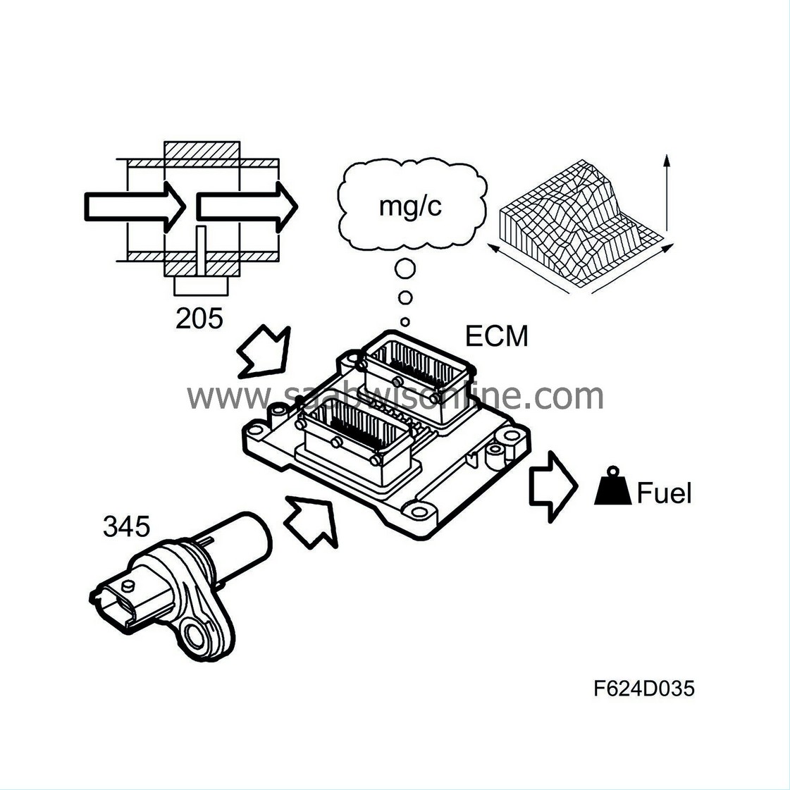
The mass air flow sensor transmits a voltage whose size is determined by mass air flow. When mass air flow increases, the voltage increases. The control module converts the voltage to grams of air/second (g/s).
It is the size of the air mass (capacity, volumetric efficiency) drawn into each cylinder that is most interesting since it is this air to which fuel shall be supplied. The control module registers the air mass taken in during one engine revolution. Since the engine is a 6-cylinder, 4-speed engine, three cylinders draw in air during the same engine revolution. The air mass that passes the mass air flow sensor is divided by three. Now the control module knows how much air each cylinder has drawn in. The unit is now changed to milligrams of air/combustion (mg/c).
To achieve lambda = 1, there must be a specific fuel/air ratio, namely 1 kg fuel to 14.7 kg air. As we know how much air has been drawn into each cylinder per combustion, the control module can easily calculate how much fuel is to be injected into the cylinders each time. The milligrams air/combustion is divided by 14.7 and the result is the number of mg fuel/combustion to be injected into the cylinder.
The value is corrected in a matrix to account for air vibrations and thereby measurement errors of the mass air flow sensor. Additionally, certain operating points need to deviate from lambda = 1.00 to generate the best driveability or emissions.
The following text is an account of why the basic fuel quantity must sometimes be adjusted to a leaner, or most often, a slightly richer mixture so that the engine will run smoothly and emissions will be kept within required limits.
Compensation, general
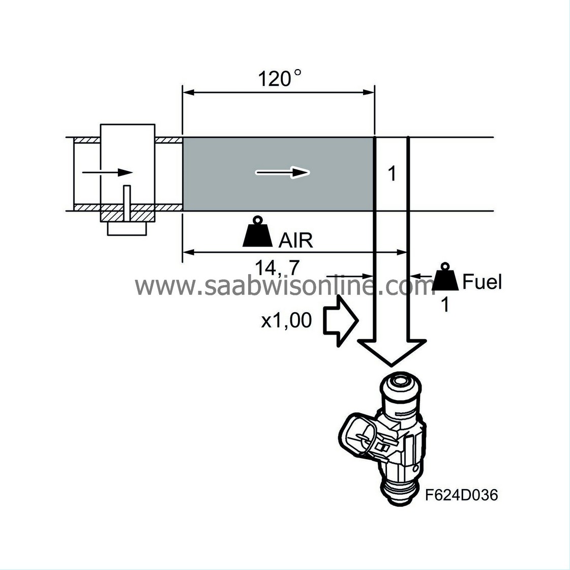
The calculated basic quantity of fuel will enable the engine to run perfectly under normal conditions, i.e. as long as it is warm and the load or rpm does not change. However, the fuel/air mixture must sometimes be corrected for the engine to function well and emissions to remain low under all conditions.
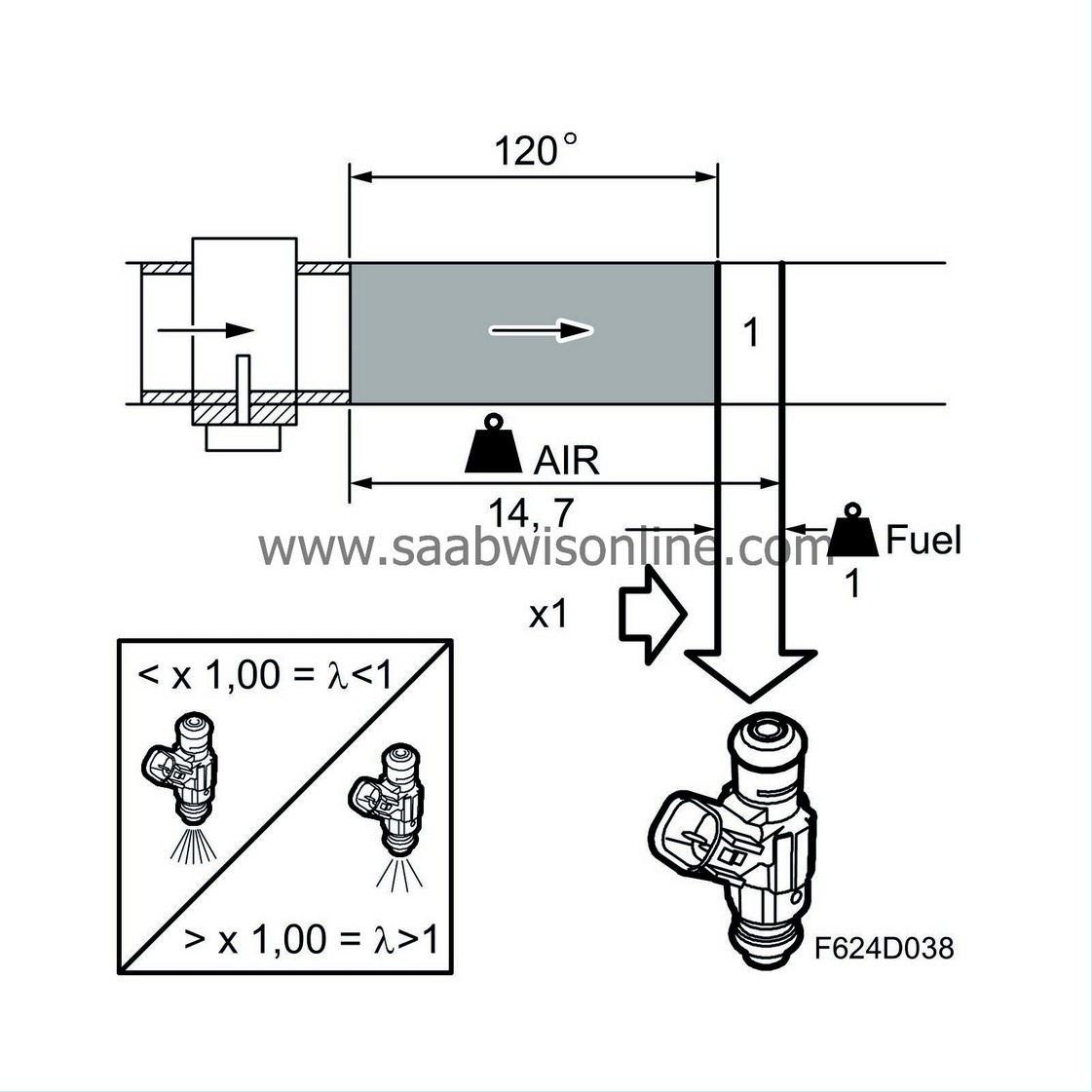
The basic fuel quantity is multiplied by a correction factor which is normally 1.00. If the correction factor is changed, for example to 1.01, the fuel quantity will be increased by 1%. If instead the correction factor is changed to 0.98, the fuel quantity will be reduced by 2%. Lambda control is usually disabled if the correction has a value other than 1.00. Otherwise the compensation would be corrected by lambda control and be ineffective.
| • |
A compensation factor over 1.00 generates a richer mixture, which is the same as a lower lambda value.
|
|
| • |
A compensation factor below 1.00 generates a leaner mixture, which is the same as a higher lambda value.
|
|
Compensation after start
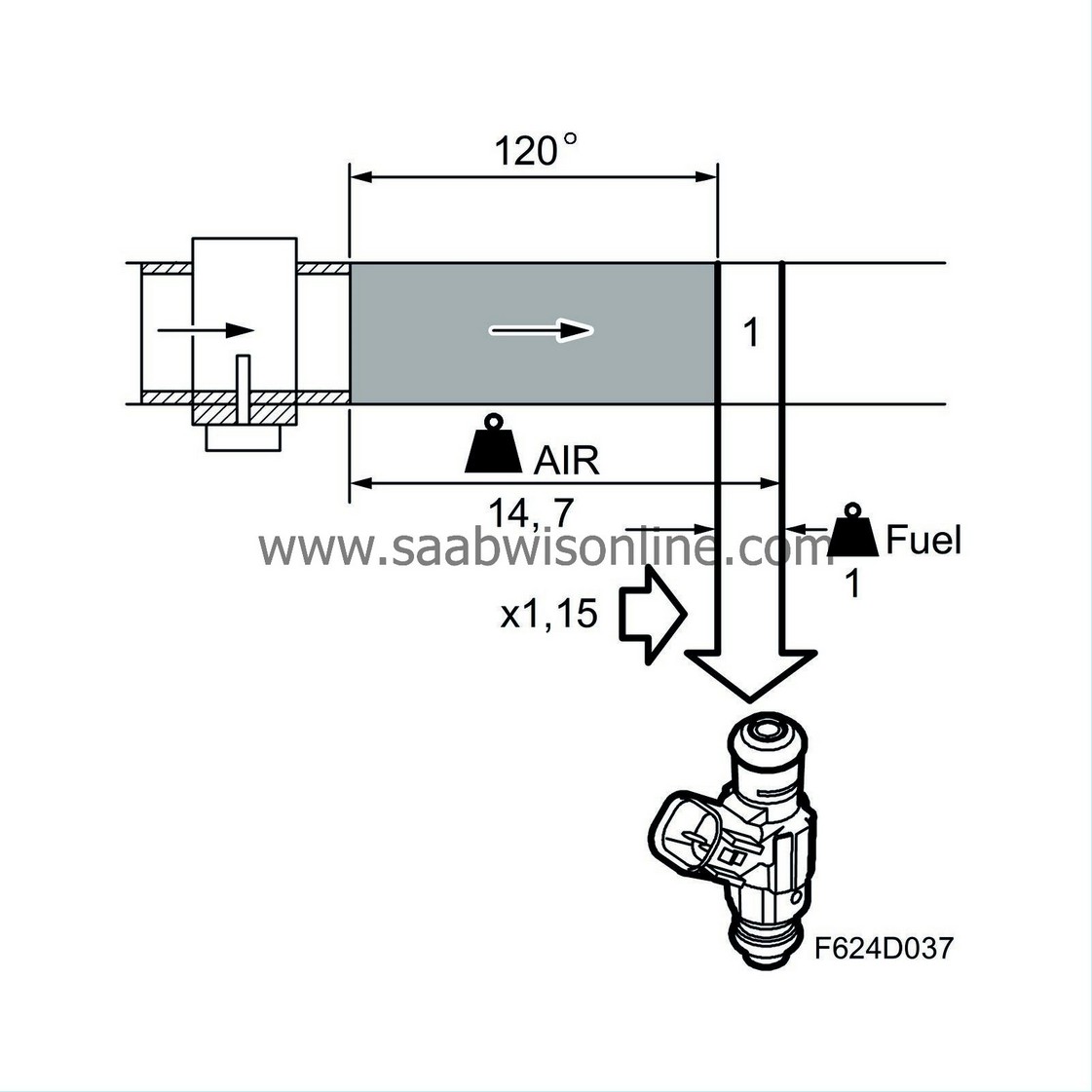
Right after engine start, the correction factor is slightly over 1 and then slowly drops to 1.00. High high over 1 the correction factor is and how long it takes before it reaches 1.00 is determined by coolant temperature.
On cars with a carburettor engine, this function is called choke.
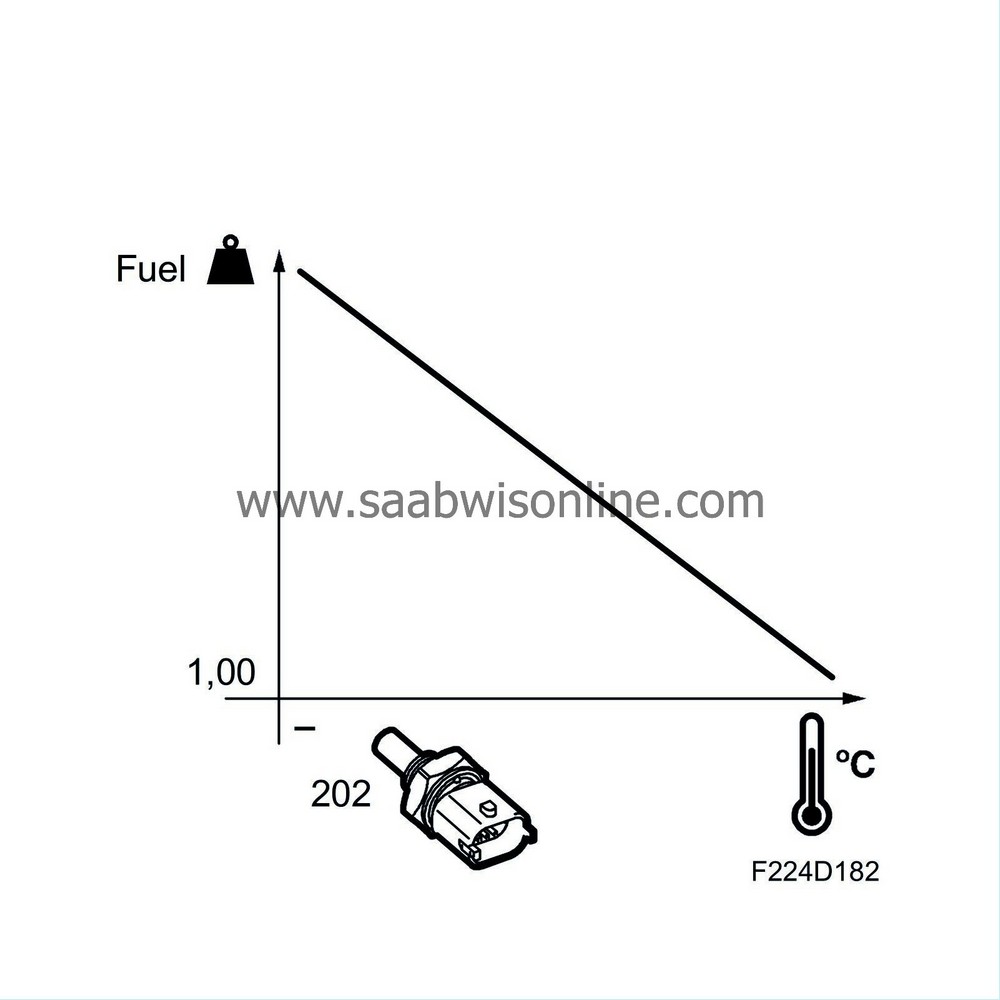
Requested lambda value drops during compensation.
Function during increasing load
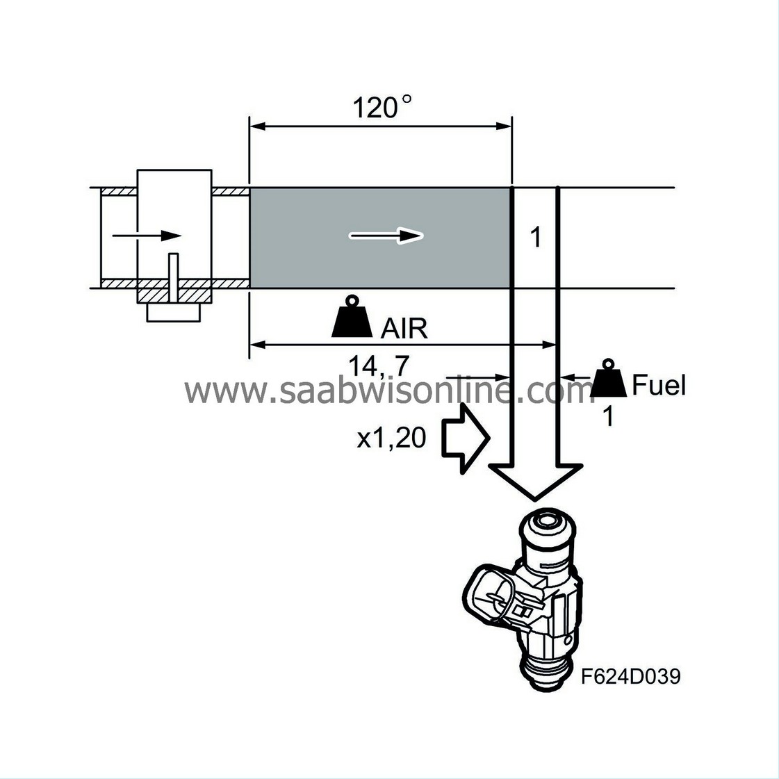
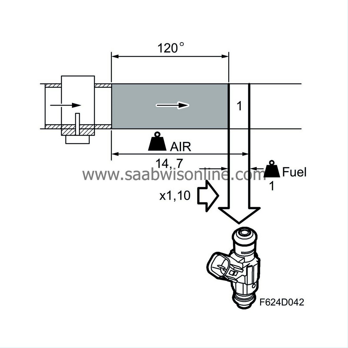
A sudden load increase causes the mg air/combustion to increase rapidly and it is well known that petrol engines then require a richer mixture. This is because fuel is deposited on the walls of the intake manifold due to the increase in pressure there, and the wet-film thickness increases. The fuel quantity used here must be replaced by a slightly larger quantity of injected fuel, which is achieved by increasing the correction factor by a few percentage points. For example, the correction factor can be increased from 1.00 to 1.03, which gives 3% more fuel.
As soon as the load increase stops, the correction factor returns to its original value.
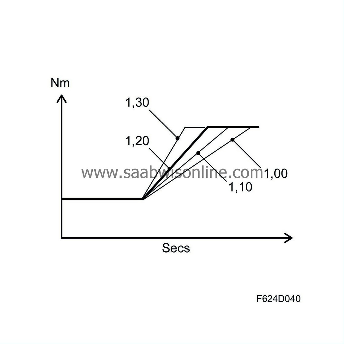
Requested lambda value drops during compensation.
Function during decreasing load
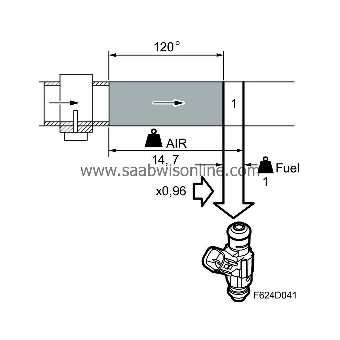
In the case of a load reduction, the function is reversed. The wet-film deposited on the walls of the intake manifold thins quickly as the pressure drops. The quantity of injected fuel must then be reduced to avoid a negative effect on emissions and fuel consumption, so the correction factor is reduced by a few percentage points. For example, the correction factor can be reduced from 1.00 to 0.96, giving a 4% reduction in fuel quantity.
How far from 1.00 the correction factor migrates in conjunction with load change depends on how quickly the air mass/combustion changes and on coolant temperature.
On a car with a carburettor engine, the function described above corresponds to the accelerator pump or damper piston.
Requested lambda value increases during compensation.
Knocking
Engine knocking is corrected through delayed firing of the cylinder in question. If knocking continues despite a delay in ignition timing, the fuel will be enriched through an increase in the correction factor.
Lambda control is active during compensation.
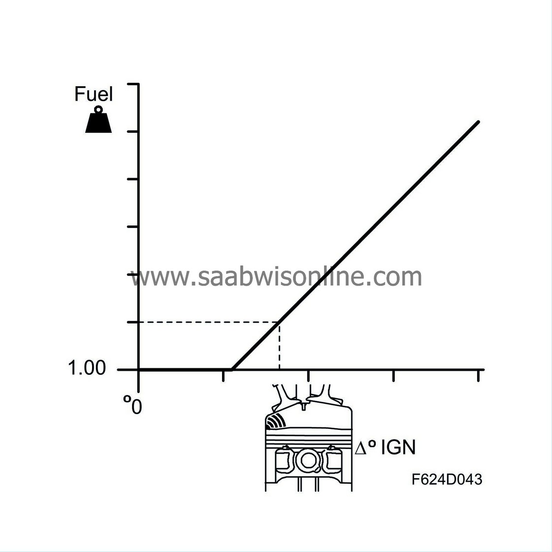
Requested lambda value drops during compensation.
Full load
At high engine load, the requested lambda value will drop to prevent engine component overheating. The lower lambda value also reduces the engine's knock tendencies.
ECM calculates exhaust temperature and corrects the lambda value to keep the calculated value within given limit values.
Lambda control is active during compensation.
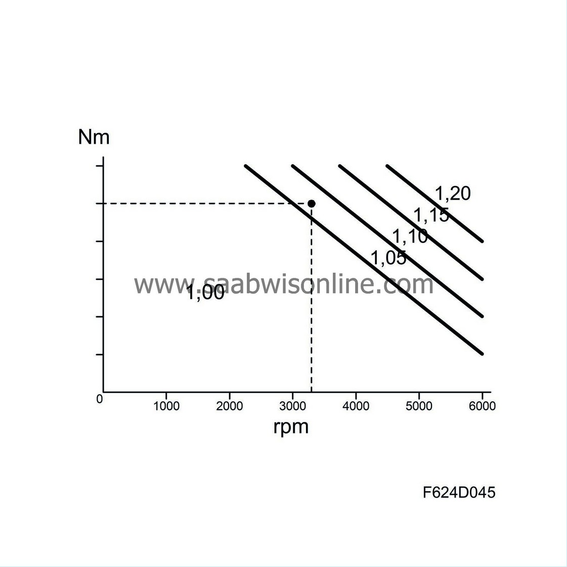
Requested lambda value drops during compensation.
| Lambda control |
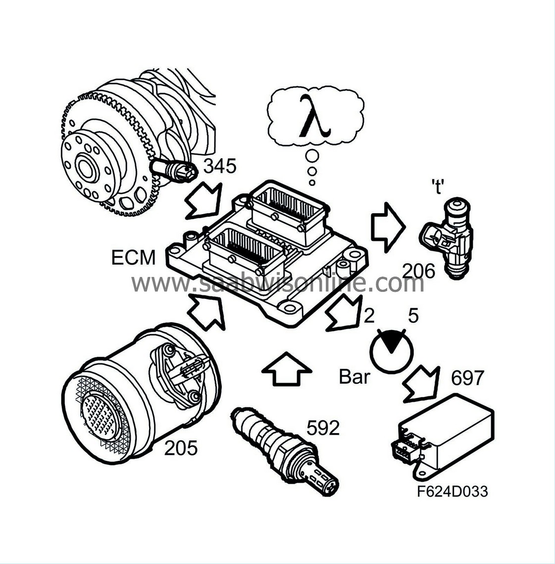
General
Using basic fuel quantity and any compensations, ECM calculates the requested lambda value. This is converted to values for:| • |
Injection timing
|
|
| • |
Fuel pressure
|
|
ECM can compare the actual lambda value with the requested one by measuring the actual lambda value in the exhaust flow. Should they deviate, ECM corrects injection timing and, as necessary, fuel pressure.
At idling speed and when driving with a moderate load, the lambda value is about 1.00.
Requested lambda value drops during high engine load.
Lambda control as well as requested and actual lambda values can be read out using the diagnostic tool.
Lambda control is active when coolant temperature exceeds 35°C.
| Purging |
General
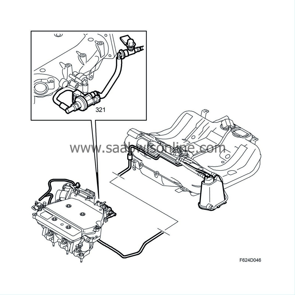
The fuel which evaporates in the tank is passed through a pipe to the evaporative emission canister. The active charcoal in the canister absorbs the hydrocarbon vapours. When the engine starts, ambient air is drawn through the canister via the purge valve into the intake manifold. The petrol vapours follow with it and are burned in the engine.Through the use of continual lambda control, purging can also be active when driving with a high engine load.
Function
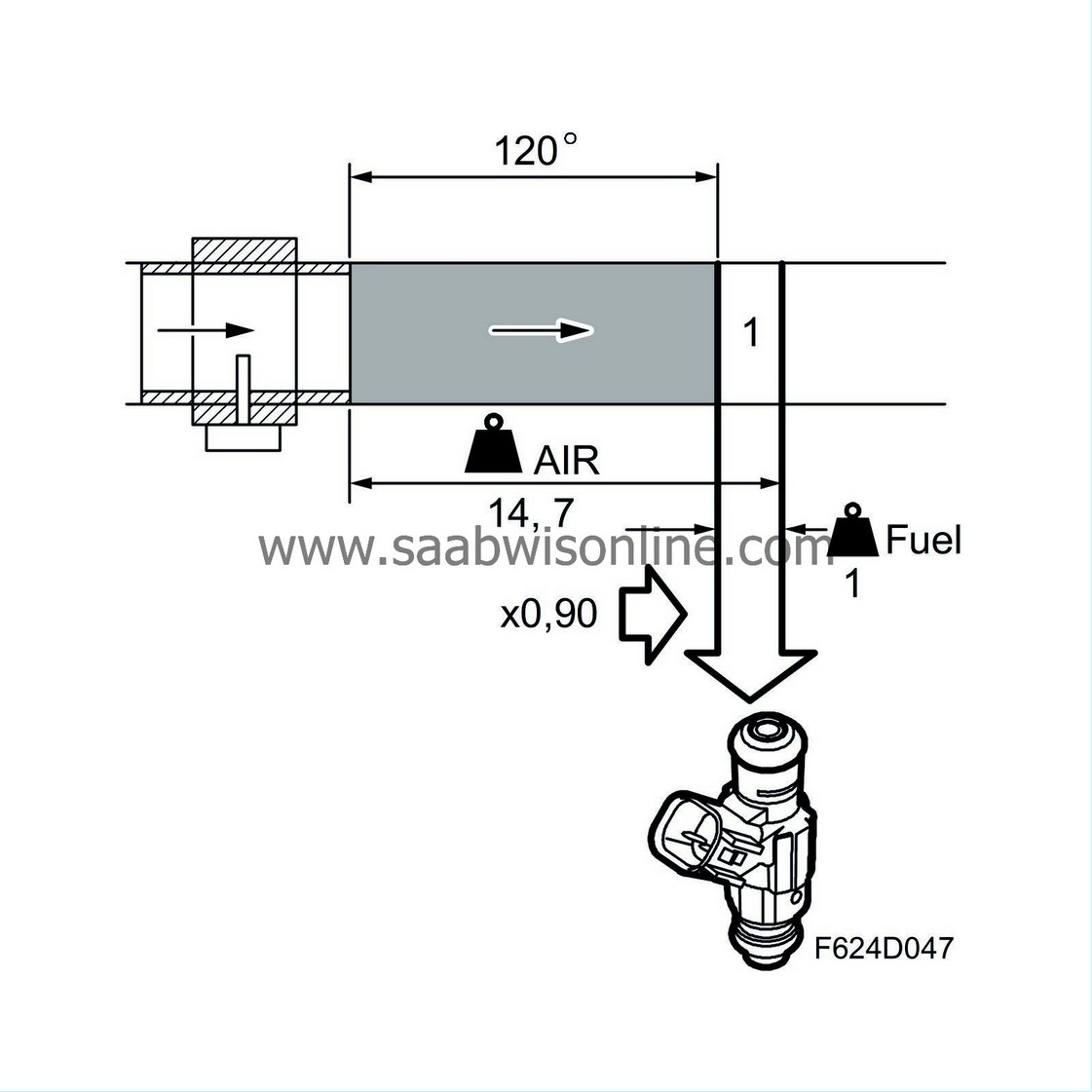
The flow is regulated by the pulse conditions so that is always constitutes a particular proportion of the total flow consumed by the engine.
If the air/fuel ratio of the flow differs from 14.7:1, lambda control is affected. However it is not the task of lambda control to correct for purge surplus. Purge therefore has a correction factor which is influenced by lambda control as soon as the purge begins. The entire lambda control deviation from 1.00 is transferred to the purge correction factor, which means that the lambda control fluctuates around 1.00 (0%) even if the purge contains large quantities of hydrocarbon or consists of pure air.
When the purge is not active, a factor of 1.00 is used and the entire fuel error is corrected by lambda control as well as multiplicative and additive adaptation
| Fuel adaptation |
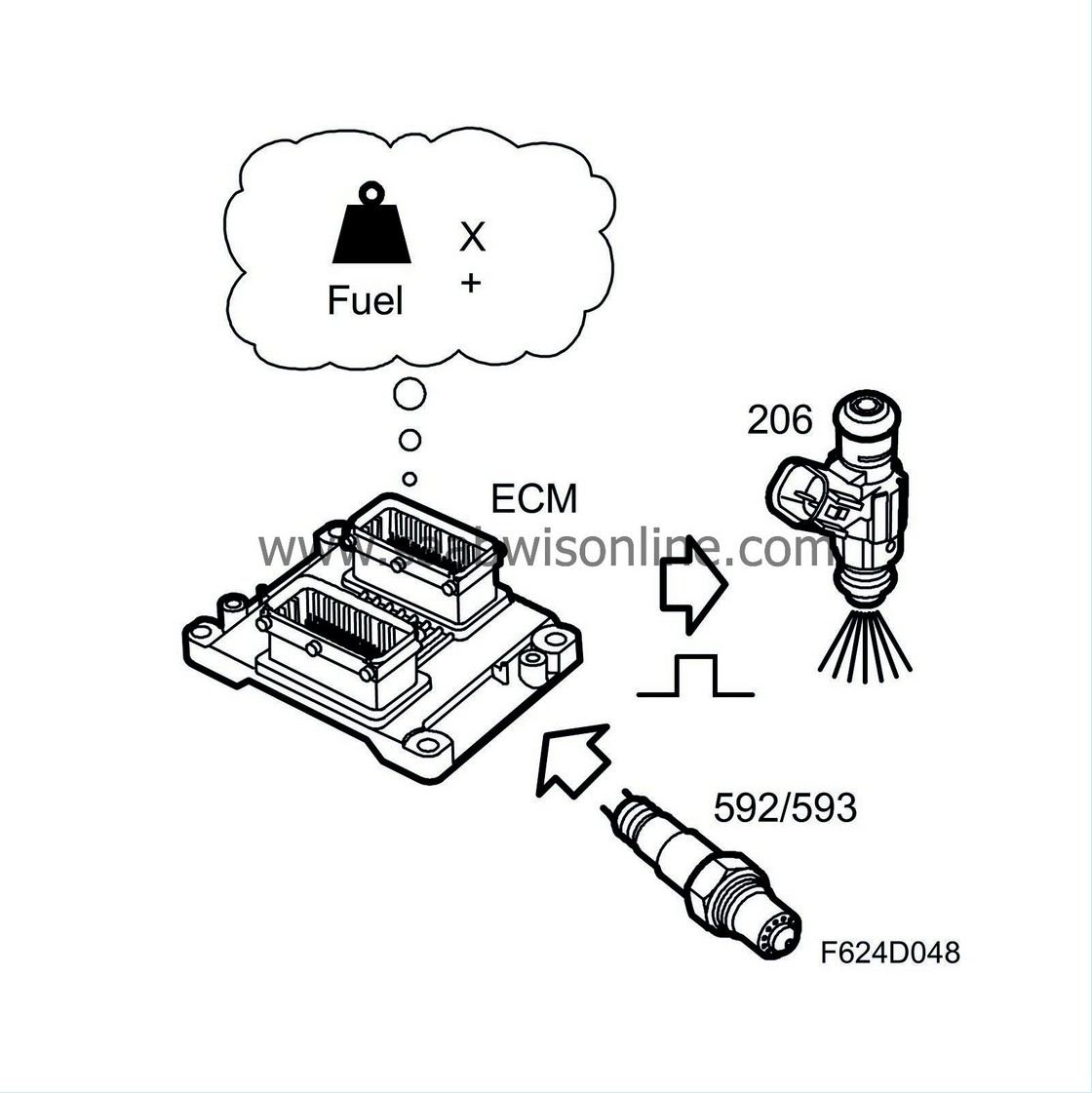
General
To compensate for e.g. normal manufacturing tolerances, ageing, etc., continuous deviations from lambda 1.00 are adapted. Fuel adaptation is divided into two sub-functions - multiplicative (partial load) and additive (idling). Together, these adaptations make lambda control work with a correction factor of around 1.00.Multiplicative fuel adaptation
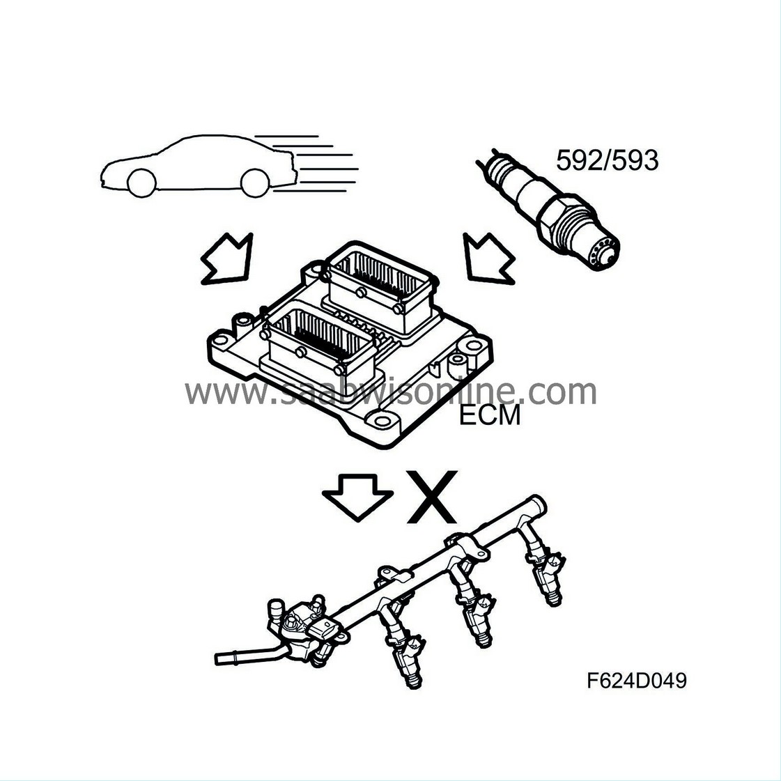
If lambda control is continuously correcting a deviation in the fuel system, it will be adapted. Adaptation takes place regularly while driving.
The fuel quantity is always multiplied by a multiplicative adaptation factor of 1.00 when the control module is new or has had its power disconnected. Multiplicative adaptation takes place under conditions of partial load. Purging is stopped during adaptation because other factors that can affect the fuel must not be active.
he entire lambda control deviation from 1.00 is transferred to the multiplicative adaptation factor. This makes it possible for the correct fuel quantity to be injected even when lambda control is not active, such as during a cold start.
After engine start, a multiplicative adaptation must always occur before an additive adaptation.
Conditions for multiplicative adaptation:
| • |
Coolant temperature over +60 °C.
|
|
| • |
Charge air temperature equal to or below +60 °C.
|
|
| • |
Load and engine speed within limits.
|
|
Additive fuel adaptation
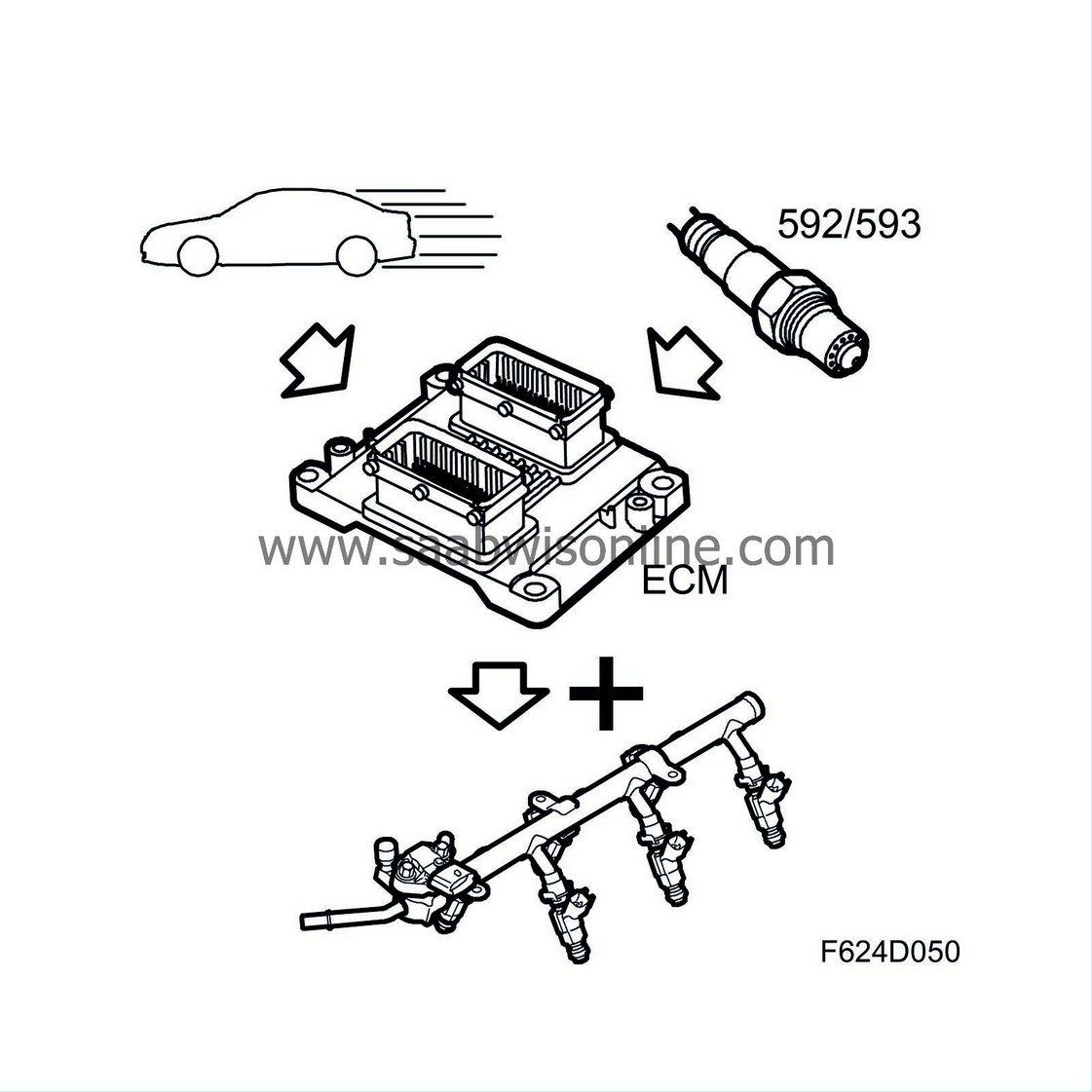
If lambda control is continuously correcting a deviation in the fuel system, it will be adapted. Adaptation takes place regularly at idling speed. The additive adaptation, which is a 0.000 ms injection duration when the control module is new or has had its power disconnected, is always added to the fuel quantity. The additive adaptation takes place at idling speed. Purging is stopped during adaptation because other factors that can affect the fuel must not be active.
The fuel quantity is added or subtracted until the lambda control value fluctuates around 1.00 (0%). Additive adaptation is required because air leaks at idling speed will lead to a greater fault that must not be adapted multiplicatively as the fuel quantity would then be far too great when the load was increased.
Conditions for additive adaptation:
| • |
Coolant temperature over +60 °C.
|
|
| • |
Charge air temperature equal to or below +60 °C.
|
|
| • |
Load and engine speed within limits.
|
|
| Starting fuel |
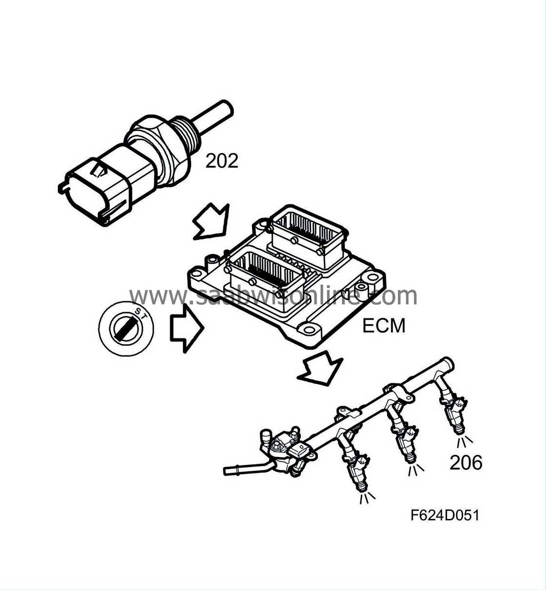
As soon as the control module has localised the large gap in the slotted ring, injection will take place according to the crankshaft angle.
The fuel quantity is still controlled by the coolant temperature alone and gradually diminishes as starter motor cranking continues.
Injection ceases if the accelerator is pressed down fully. So if the engine is suspected of being flooded, it can be ventilated.
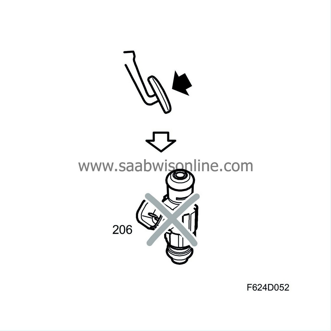
As soon as engine speed exceeds 500 rpm, the engine is deemed started and fuel quantity is calculated using the mass air flow sensor as primary sensor.
| Injection duration |

Fuel mass per combustion
The fuel mass to be injected into the engine per combustion has been calculated. The value is divided by 0.76 and is now converted to ml petrol/combustion.The volume is accumulated for each combustion and the value sent on the bus. The main instrument unit uses the value to correct the tank gauge and the information display uses it to calculate the petrol consumption.
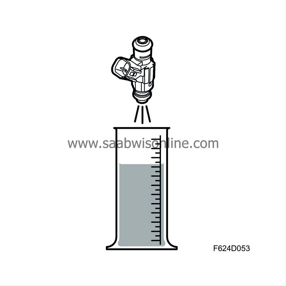
Injector opening time
Fuel volume/combustion is converted to injector opening duration based on knowledge of the injector flow.Injection twice/combustion
Before the camshaft position has been detected, injection will take place semi-sequentially at 120 degree intervals. This means two cylinders at a time in the following order: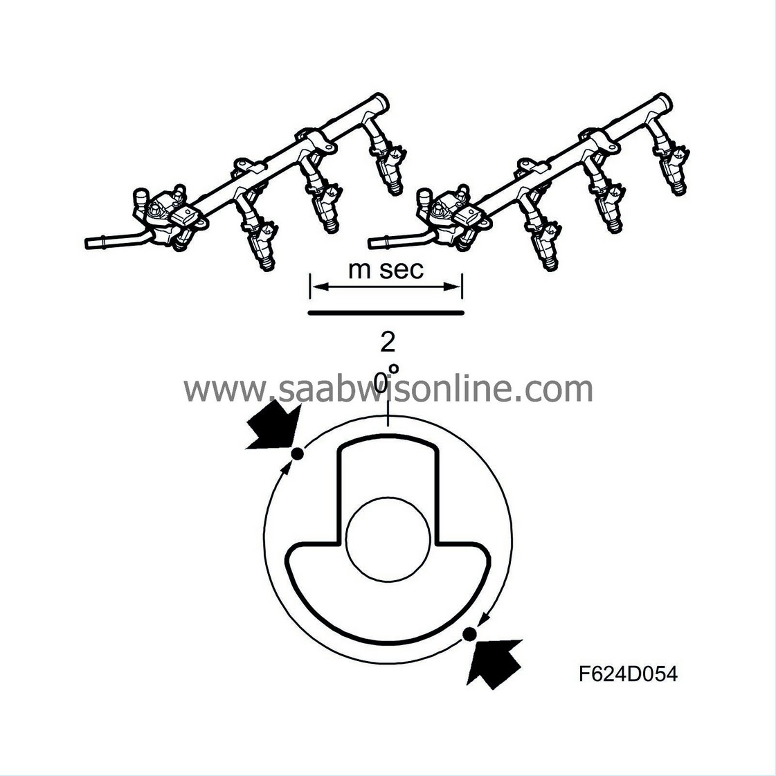
| • |
Cylinders 1+4
|
|
| • |
Cylinders 2+5
|
|
| • |
Cylinders 3+6
|
|
Each injector injects fuel once per crankshaft rotation and this means that the basic duration must be divided by two.
Needle lift compensation
The amount of time it takes for the needle in the injector to lift is voltage-dependent. Depending on the battery voltage, the delay time is added to the basic duration.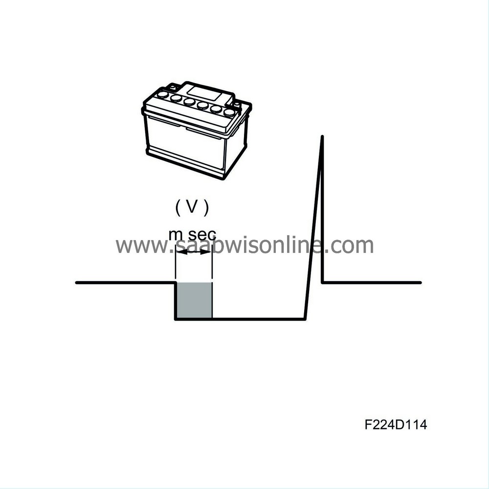
Fuel shut-off
If any of the following criteria are fulfilled, fuel shut-off will take place:
| • |
Power supply +15 not found
|
|
| • |
Fully depressed accelerator pedal while starter motor is cranking
|
|
| • |
Engine speed exceeding 6600 rpm
|
|
| • |
Immobilizer code faulty.
|
|
| • |
Major fault in throttle control
|
|
| • |
Engine braking during certain conditions
|
|
| • |
Cylinder shut-off upon fault in throttle control
|
|
| • |
Cylinder shut-off when overheating protection active
|
|
Activating the injectors
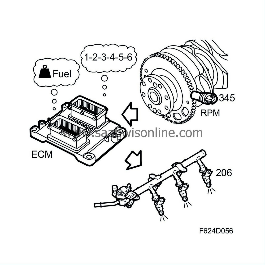
ECM controls the injector that is to deliver fuel. Sequence is governed by firing order. At which crankshaft angles injection is to occur depends on the operating conditions. The injection is divided into a pre-injection and a main injection.
The pre-injection occurs when the intake values through evaporation of the fuel toward the valve stem cap. This improves fuel preparation. The degree of pre-injection depends on coolant temperature. At low temperatures, the degree of pre-injection is null or small.
The main injection occurs when the intake valves are open. Evaporation of the fuel absorbs heat from the combustion chamber, thereby cooling the engine. This results in reduced thermal stress and reduced propensity toward knocking.
The injectors are supplied with voltage from the main relay (229) and are grounded by the control module as follows:
| • |
Injector 1 is regulated from pin 63(A)
|
|
| • |
Injector 2 is regulated from pin 62(A)
|
|
| • |
Injector 3 is regulated from pin 46(A)
|
|
| • |
Injector 4 is regulated from pin 45(A)
|
|
| • |
Injector 5 is regulated from pin 47(A)
|
|
| • |
Injector 6 is regulated from pin 64(A)
|
|


