Control module, glow plug (596)
|
|
Control module, glow plug (596)
|
Control module, glow plug (596)
The task of the glow plug control module is to activate the glow plugs upon the command of the engine management system.
DT/DTH
The control module has a relay output 12V

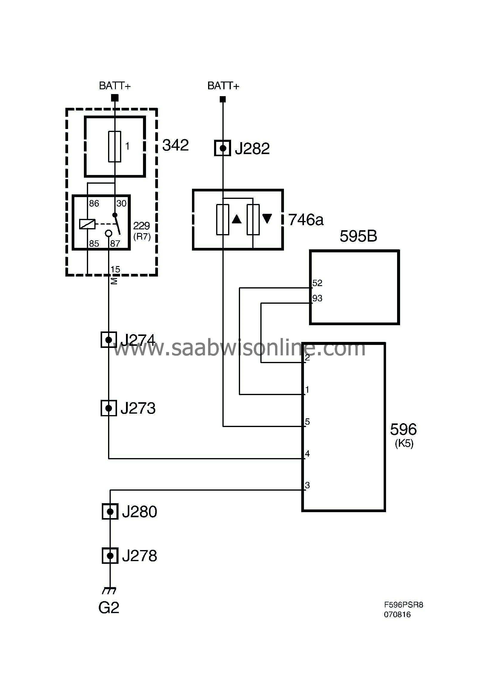
DTR
The control module has a transistor output 12V PWM.
|
Pin No.
|
Signal type
|
Description
|
|
1
|
Output
|
Connected to glow plug cylinder 1 and 2.
|
|
2
|
Output
|
Connected to glow plug cylinder 3 and 4.
|
|
3
|
Power supply +30
|
Connected to fuse holder 746a.
|
|
6
|
Ground
|
Connected to grounding point G2.
|
|
7
|
Signal
|
Connected to ECM pin 93(B).
|
|
8
|
Diagnostics
|
Connected to ECM pin 52(B).
|
|
9
|
Power supply
|
Via main relay 229. Connects to UEC pin 15(M).
|
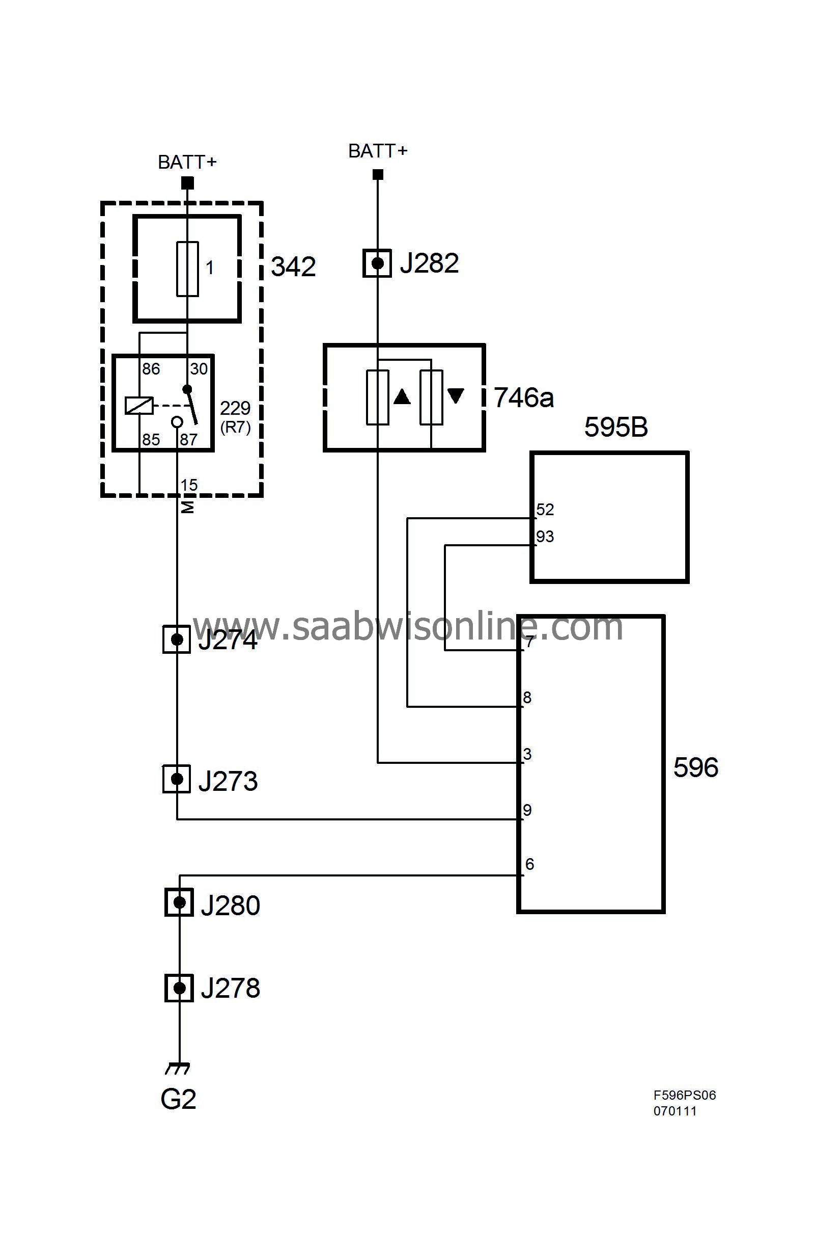
The control module has an internal diagnostic function which monitors the glow plugs. When a fault arises the glow plug control module sends an error message to control module pin 52(B).
When the engine control module pulls pin 93(B) to ground, the glow plug control module is activated, meaning pins 1 and 2 of the control module are supplied voltage.
When voltage on pin 3 (B+) exceeds 12 V, such as when the engine has been started, the control module begins alternately supplying power to pins 1 and 2. Alternation between pins 1 and 2 is done with 5 Hz. The power supply is pulsed alternately to lower power consumption.
Contact K5
|
Pin No.
|
Signal type
|
Description
|
|
1
|
Signal. PWM
|
Connected to ECM pin 93(B).
|
|
2
|
Diagnostics
|
Connected to ECM pin 52(B).
|
|
3
|
Ground
|
Connected to grounding point G2.
|
|
4
|
Power supply
|
Via main relay 229. Connects to UEC pin 15(M).
|
|
5
|
Power supply +30
|
Connected to fuse holder 746a.
|
Diagram, contact K5
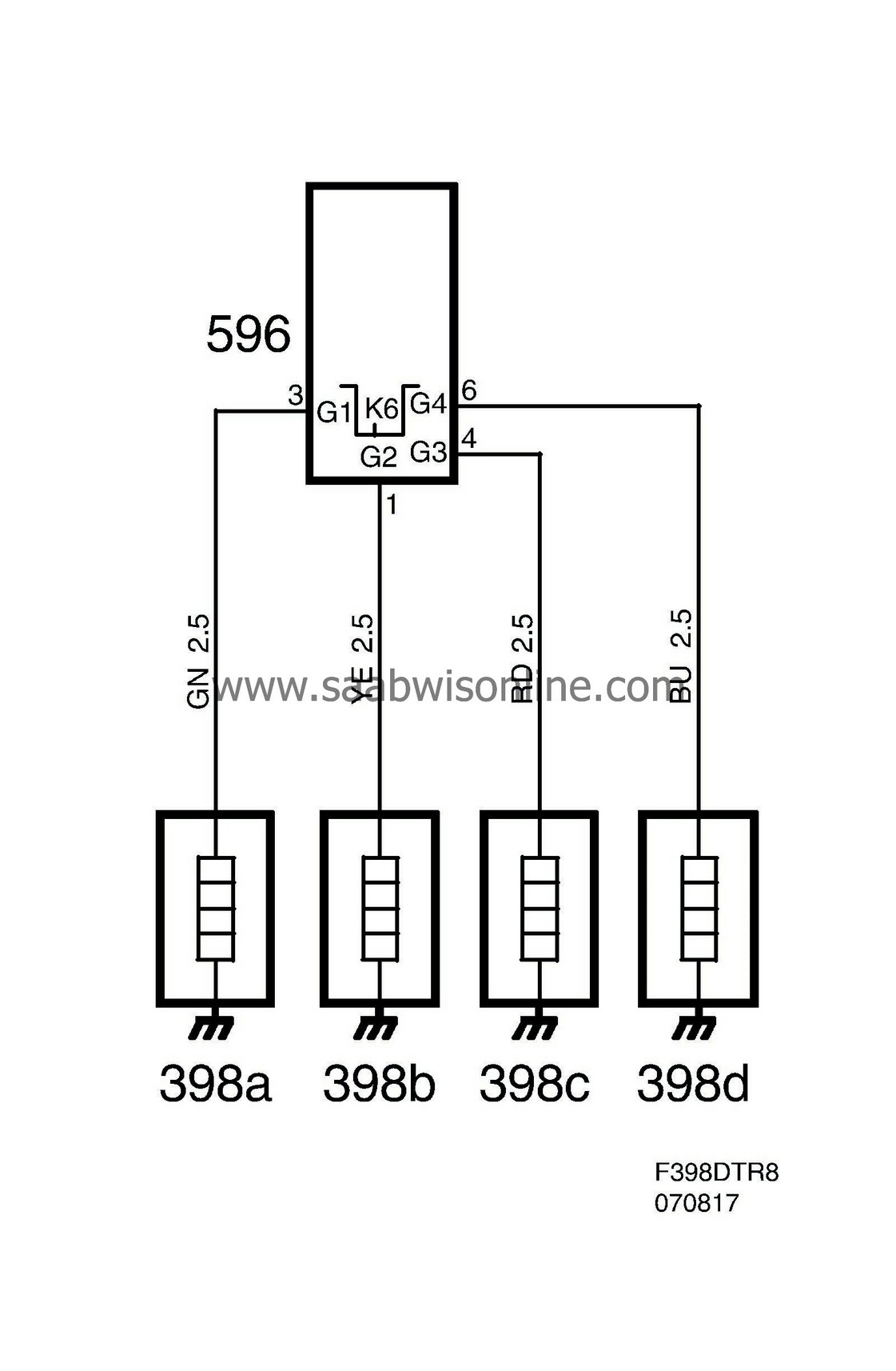
Contact K6
|
Pin No.
|
Signal type
|
Description
|
|
1
|
Power supply PWM
|
Connected to glow plug 398b cylinder 2
|
|
2
|
-
|
-
|
|
3
|
Power supply PWM
|
Connected to glow plug 398a cylinder 1
|
|
4
|
Power supply PWM
|
Connected to glow plug 398c cylinder 3
|
|
5
|
-
|
-
|
|
6
|
Power supply PWM
|
Connected to glow plug 398d cylinder 4
|
Diagram, contact K6
The control module has an internal diagnostic function which monitors the glow plugs. When a fault arises the glow plug control module sends an error message to control module pin 52(B).
When the engine control module switches pin 93(B) to ground, the glow plug control module is activated. At which point one glow plug is energised at a time by a PWM voltage, the frequency of which is 35 Hz and voltage is B+, in order that average voltage should not exceed 4.4 V. This is in order to reduce the total power consumption.
As battery voltage is never below the rated voltage of 4.4 V for the glow plugs they always receive full output during the engagement period.


