Control module, TCS (382)/ESP (671), B207, B284 RHD, Z19
|
|
Control module, TCS (382)/ESP (671), B207, B284 RHD, Z19
|
|
1.
|
Touch ground.
|
Important
|
|
ESD-SENSITIVE COMPONENT
|
|
Earth yourself by touching the car body before plugging in / unplugging components.
Do not touch the component pins
. Read
Before removing a control module
before changing a control module.
|
|
|
|
|
4.
|
Separate the connector from the control module.
|
|
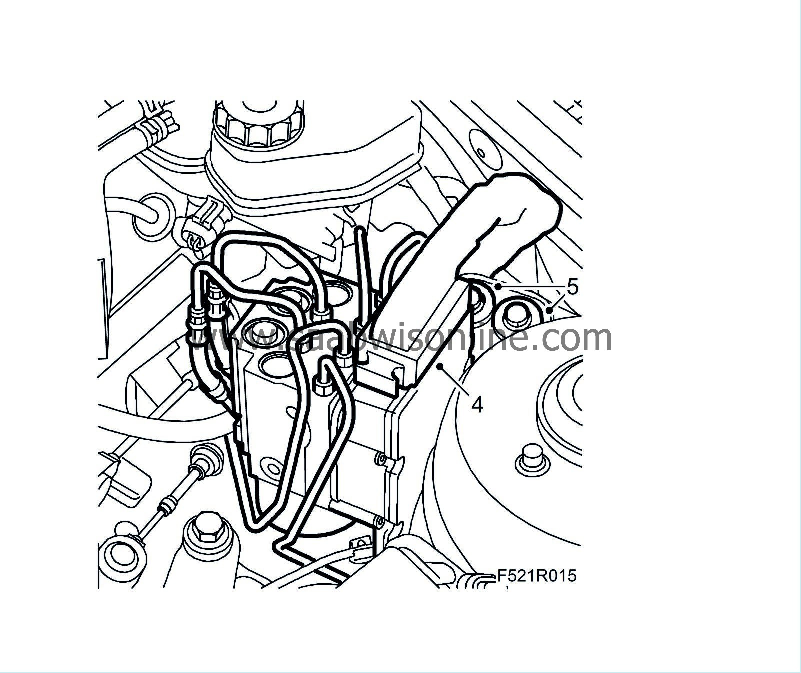
5.
|
Remove the bracket from the suspension strut tower.
|
|
6.
|
Raise the TCS/ESP assembly around 25 mm so that the control pins come out of the rubber bush.
|
|
7.
|
Move the assembly towards the engine so that the assembly's bolts are accessible with a ratchet handle and bits. Suspend the assembly with a
83 95 212 Strap
.
|
Note
|
|
Be careful with the brake pipes.
|
|
|
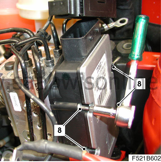
8.
|
Remove the four bolts. Leave the lower rear bolt in the control module.
|
|
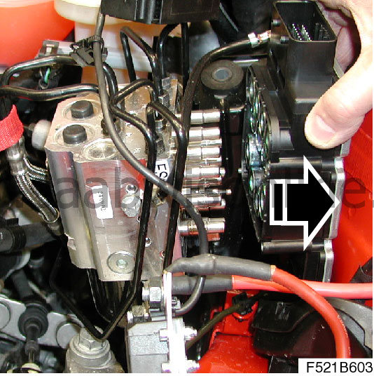
9.
|
Remove the electronic unit by twisting out.
|
Note
|
|
Ensure that the bolts come with it. Remove the gasket from the hydraulic unit if it does not follow the control module.
|
|
|
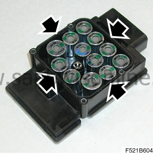
1.
|
Check that the gasket sits correctly on the new control module.
|
|
2.
|
Fit the inner bottom rear screw and fit the control module to the assembly.
Fit the bolts.
Tightening torque 2.5 Nm (1.8 lbf ft)
|
Note
|
|
Tighten the bolt alternately.
|
|
|
3.
|
Fit the assembly in place with the guide pin in the rubber bush. Make sure the brake pipes are secured in the clips on the MacPherson strut tower.

|
|
4.
|
Fit the bolts to the suspension strut tower.
Tightening torque 25 Nm (18 lbf ft)
|
Important
|
|
Take care when plugging in the connector so as not to damage or press out the pins/sleeves in the connector. For further information regarding connectors, refer to
Connectors, handling and inspection
.
|
|
|
|
|
5.
|
Attach the connector to the control module.
|


