PRE-RELEASE
Subframe, B284, 4WD
| Subframe, B284, 4WD |
| To remove |
| 1. |
Remove the upper bumper shell attachments.
|
|
| 2. |
Remove the air filter cover.
|
||||||||||
| 3. |
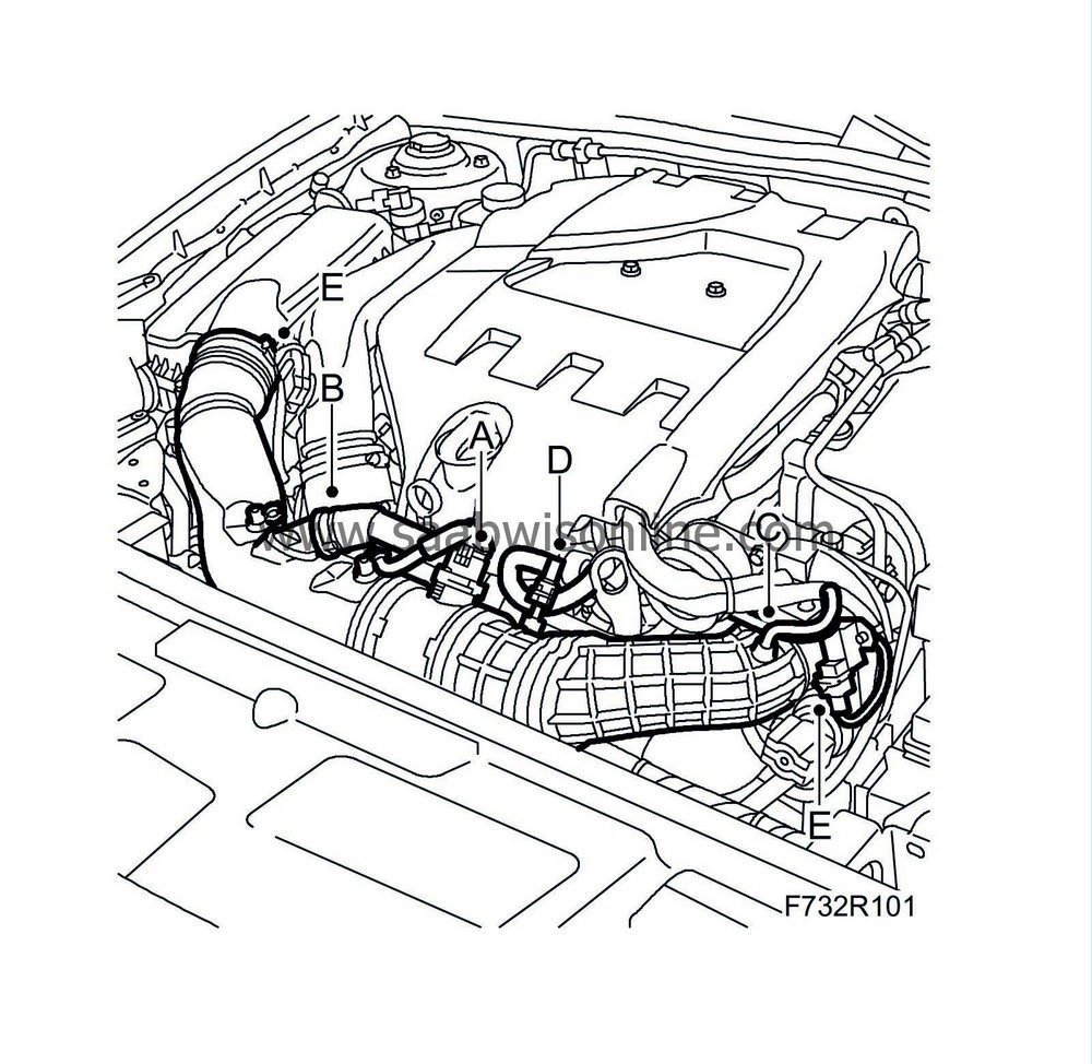
Unplug the mass air flow sensor connector (A).
|
|
| 4. |
Detach the secondary air pipe (B) and delivery hose (C) from the turbocharger intake manifold and crankcase ventilation pipe (D).
|
|
| 5. |
Detach the turbocharger intake manifold (E) from the air cleaner housing cover and the turbocharger.
|
|
| 6. |
Hang two
83 95 212 Straps
in place over the radiator member and the radiator unit so that they are accessible from below.
|
|
| 7. |
Raise the car.
|
|
| 8. |
Remove the front wheels.
|
|
| 9. |
Remove the lower front cover (A).

|
|
| 10. |
Bind the radiator unit tightly with the straps.
|
|
| 11. |
Remove the radiator brackets (B) from the subframe.
|
|
| 12. |
Remove the
propeller shaft
.
|
|
| 13. |
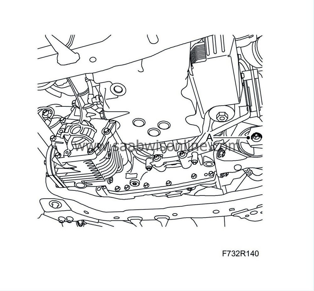
Remove the engine's front torque rod (A) from the subframe.
|
|
| 14. |
Remove the bolt and nut (B) which attach the suspension arm to the steering swivel member on both sides.

|
|
| 15. |
Cars with xenon headlights:
Remove the level sensor (C) on the left-hand suspension arm.
|
|
| 16. |
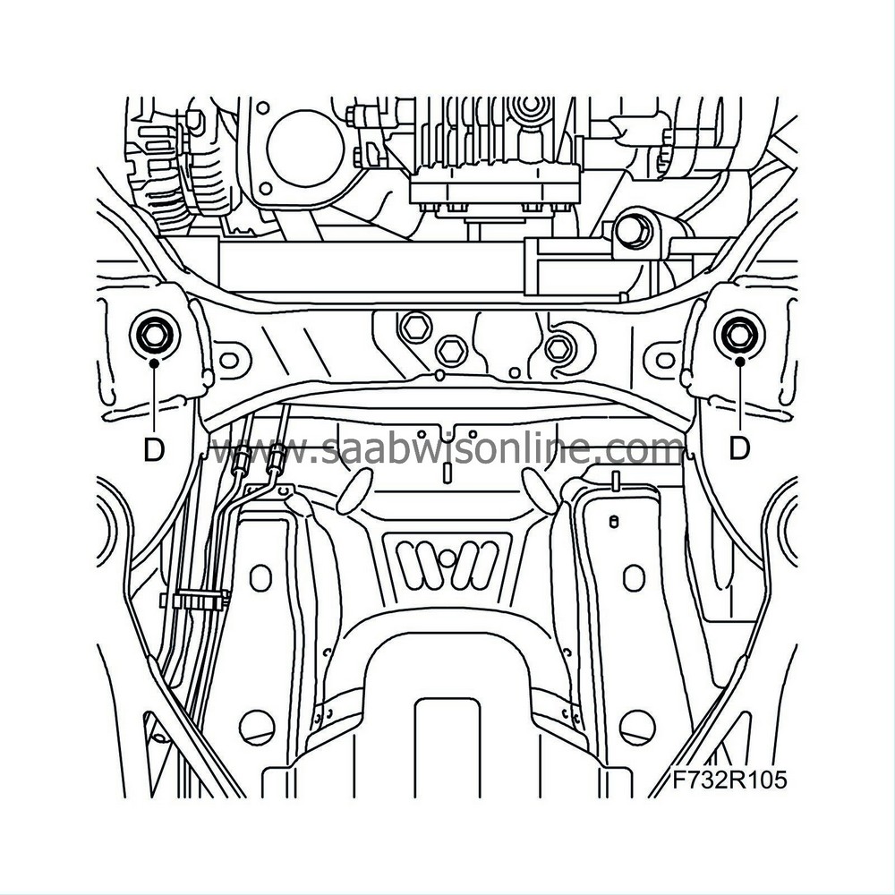
Remove the steering gear from the subframe (D). Look after the nuts and washers. Allow the steering gear to remain suspended.
|
|
| 17. |
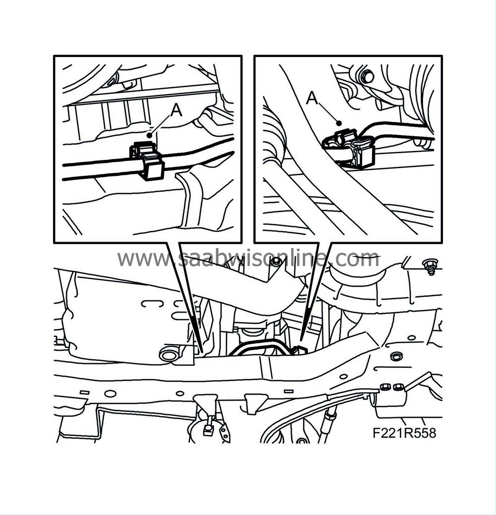
Open the clips (A) that secure the power steering pipe to the subframe.
|
|
| 18. |
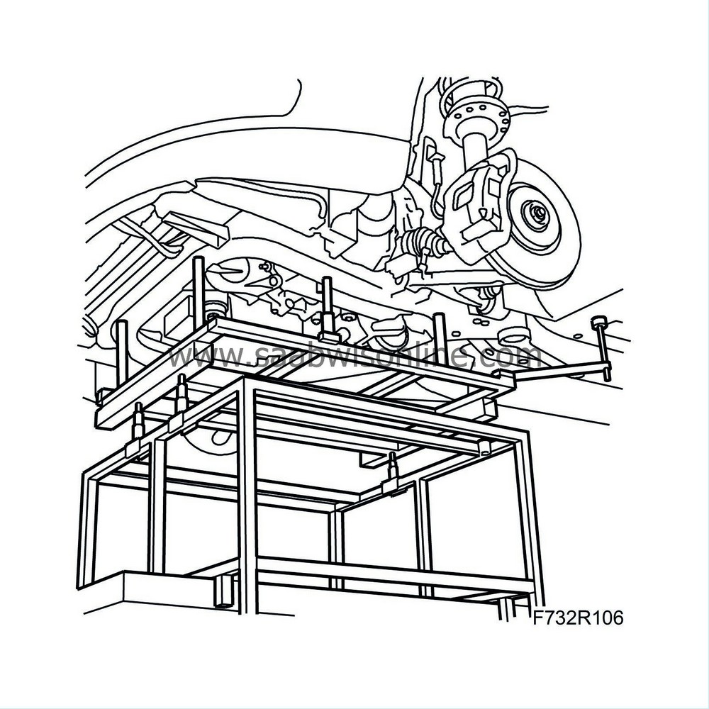
Position
83 95 311 Trolley lift
with
83 94 801 Parent fixture
and
83 96 137 Centring tool, subframe/body
.
|
|
| 19. |
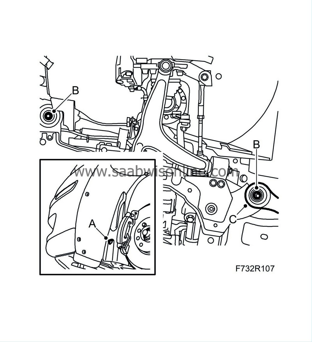
Remove the front part of the wing liner (A) and fold away slightly.
|
|
| 20. |
Remove the subframe bolts (B) on both sides. Remove the stays (C) from the body.
|
|
| 21. |
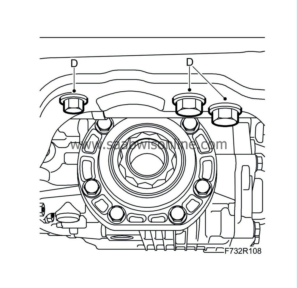
Remove the bolts (D) securing the rear torque rod to the subframe.
|
|
| 22. |
Lower the subframe slightly.
|
|
| 23. |
Pull out the suspension arms ball-and-socket joints from the steering swivel members.
|
|
| 24. |
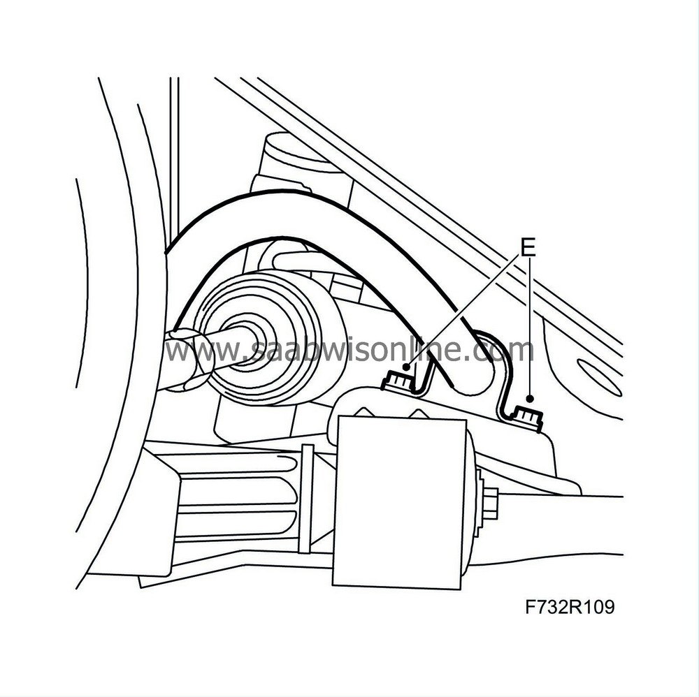
Remove the anti-roll bar (E) from the subframe.
|
|
| 25. |
Lower the subframe.
|
|
| 26. |
Subframe replacement:
Remove the suspension arms and rear torque rod (A).

|
|
| To fit |
| 1. |
Position the frame on
83 95 311 Trolley lift
with
83 94 801 Parent fixture
and
83 96 137 Centring tool, subframe/body
.
|
|
| 2. |
Subframe replacement:
Fit the suspension arms (A) in a horizontal position.
Tightening torques: Rear bush to subframe 65 Nm +135° (48 lbf ft +135°) Front bush (A) to subframe 65 Nm +135° (48 lbf ft +135°) |
|
| 3. |
Lift the frame.
|
|
| 4. |
Fit the anti-roll bar (E) to the subframe.

|
|
| 5. |
Fit the bolts (D) securing the rear torque rod to the subframe.
Tightening torques: M10 65 Nm (48 lbf ft) M12 120 Nm (88 lbf ft) 
|
|
| 6. |
Fit the ball joints for the suspension arms in the steering swivel member.
|
|
| 7. |
Lift the subframe into place and align
83 96 137 Centring tool, subframe - body
with the locating holes in the body.
|
|
| 8. |
Attach the power steering pipe to the plastic clips (A) on the subframe.

|
|
| 9. |
Lift the subframe so that the inner sections of the bushes are pressing against the body. Fit the front subframe bolts (B) on both sides.
Tightening torque 75 Nm +135° (55 lbf ft +135°) 
|
|
| 10. |
Fit the stays and the rear subframe bolts (B) on both sides. Enter the rear stay bolts (C) before tightening the subframe bolts.
Tightening torque 75 Nm +135° (55 lbf ft +135°) |
|
| 11. |
Lower and pull away the trolley lift.
|
|
| 12. |
Tighten the rear stay bolts (C).
Tightening torque 90 Nm +45° (66 lbf ft +45°) |
|
| 13. |
Fit the front part of the wing liner (A).
|
|
| 14. |
Fit the steering gear (D) with bolts, washers and nuts.
Tightening torque 50 Nm +60° (37 lbf ft +60°) 
|
|
| 16. |
Fit the bolt and nut (B) which attach the suspension arm to the steering swivel member on both sides.
Tightening torque 50 Nm (37 lbf ft) |
|
| 17. |
Fit the engine's front torque rod (A) to the subframe.
Tightening torque 60 Nm +90° (44 lbf ft +90°) 
|
|
| 18. |
Set up the
83 96 145 Centring tool, subframe/engine
and check that the engine is positioned correctly in relation to the subframe. Remove the centring tool.
|
|
| 19. |
Fit the
propeller shaft
.
|
|
| 20. |
Fit the radiator brackets (B) to the subframe.
Tightening torque 47 Nm (35 lbf ft)

|
|||||||
| 21. |
Remove the straps.
|
|
| 22. |
Fit the lower front cover (A).
|
|
| 23. |
Fit the wheels.
|
|
| 24. |
Lower the car to the floor.
|
|
| 25. |
Attach the turbocharger intake manifold (E) to the air cleaner housing cover and the turbocharger.

|
|
| 26. |
Attach the secondary air pipe (B) and delivery hose (C) to the turbocharger intake manifold and crankcase ventilation pipe (D).
|
|
| 27. |
Plug in the mass air flow sensor connector (A).
|
|
| 28. |
Fit the air filter cover.
|
|
| 29. |
Fit the upper bumper shell attachments.
|
|
| 30. |
Check the straight-ahead position of the steering wheel when driving on a level road. Adjust if necessary.
|
|
| 31. |
During subframe replacement:
Carry out
Four wheel alignment
.
|
|

 Warning

