PRE-RELEASE
Replacing the hydraulic lines and wiring harness, front bow
| Replacing the hydraulic lines and wiring harness, front bow |
| To remove |
| 1. |
Raise the soft top fully.
|
|
| 2. |
Remove
Luggage compartment side trim, CV
on the right hand side.
|
|
| 3. |
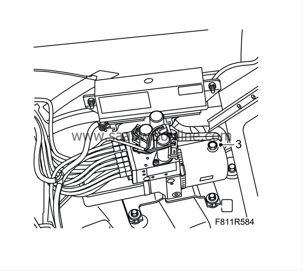
Remove the oil filler plug (for pressure equalisation). Refit the plug.
|
|
| 4. |
Open the soft top and leave the soft top cover open.
|
|
| 5. |
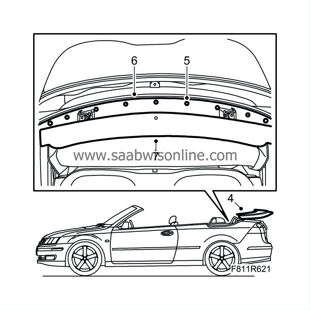
Remove the clips' centre pins to the mounting plate.
|
|
| 6. |
Remove the mounting plate with the clips.
|
|
| 7. |
Lift the trim in the front and take it out.
|
|
| 8. |
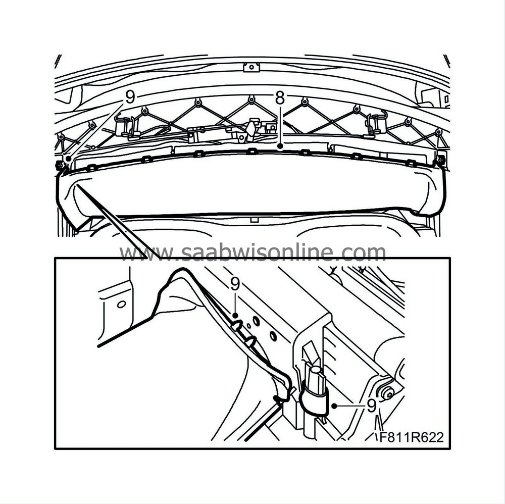
Unhook the headlining attachment eyes to the first bow on the right-hand side.
|
|
| 9. |
Remove the headlining plastic plugs and the outer roof attachment eye on the right-hand side of the first bow.
|
|
| 10. |
Operate the soft top to its centre position; the soft top first bow must point straight up.
|
|||||||||
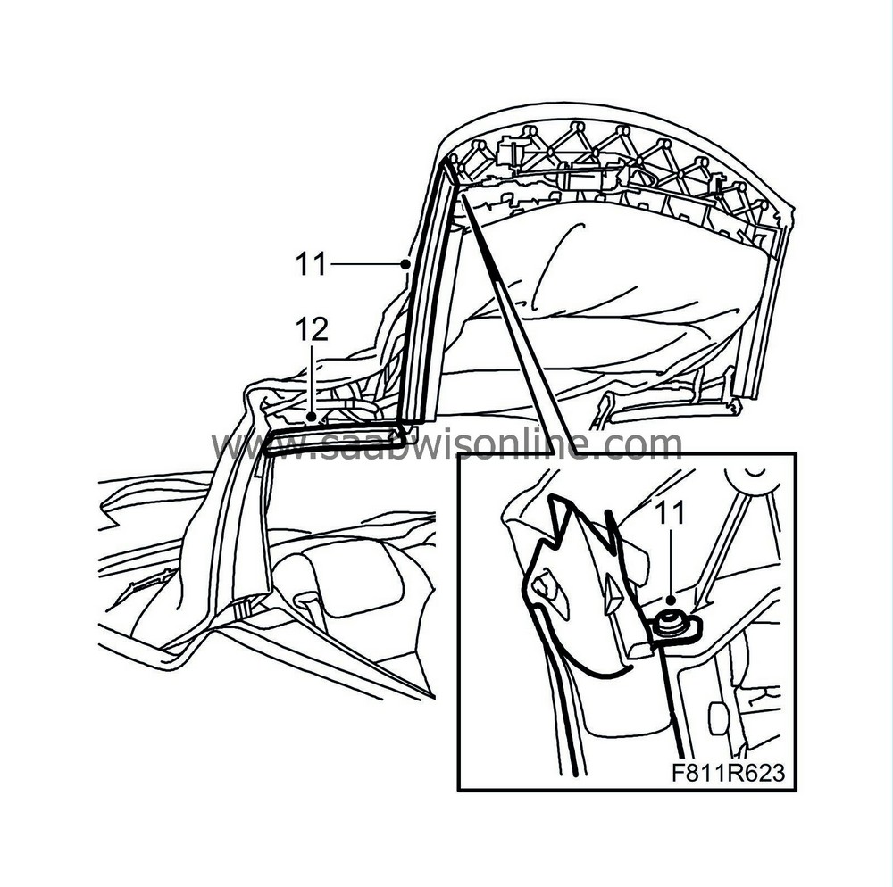
| 11. |
Remove the screw and the seal from the front rail.
|
|
| 12. |
Remove the seal from the centre rail.
|
|
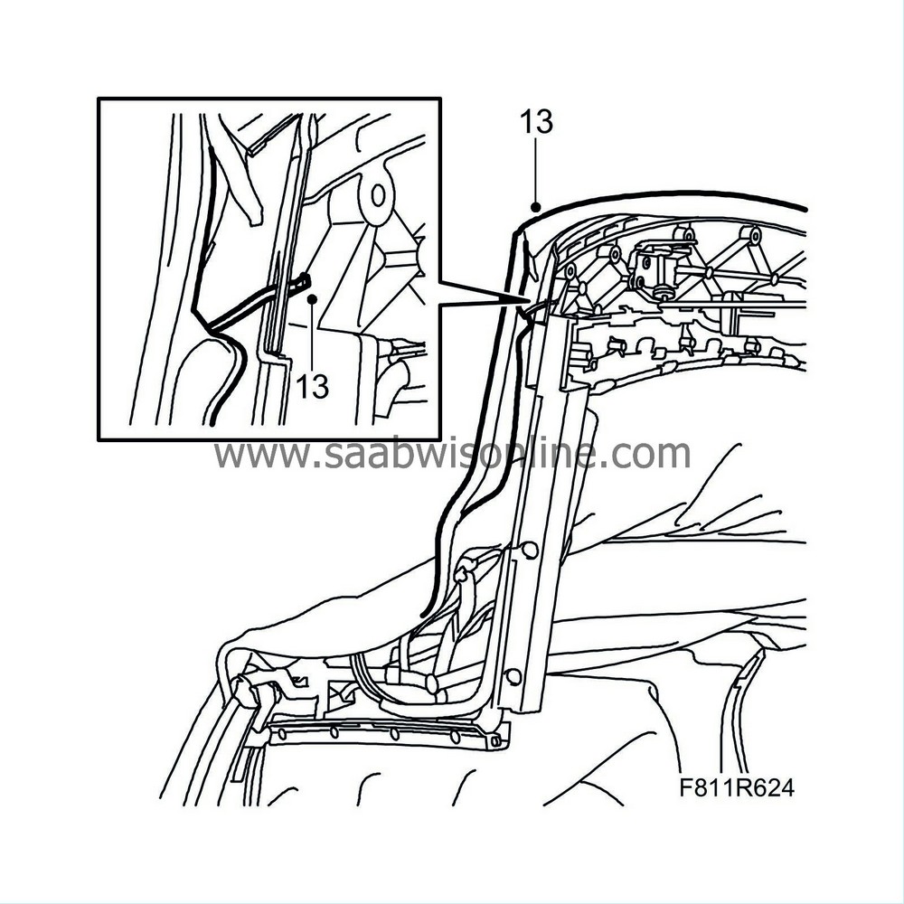
| 13. |
Detach the outer roof from the right-hand side of the first bow.
|
|
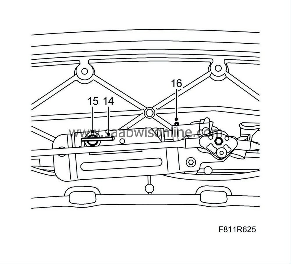
| 14. |
Turn the lock hook so that the cable lock and the hydraulic cylinder fastening pin are accessible.
|
|
| 15. |
Remove the clip for the hydraulic cylinder piston rod.
|
|
| 16. |
Unhook the wire clip from the fastening pin.
|
|
| 17. |
Pull out the fastening pin for the hydraulic cylinder.
|
|
| 18. |
Position a cloth under the cylinder to catch any hydraulic oil that may run out. Remove the hydraulic cylinder from the holder so that it is easier to access the hydraulic lines' connections.
|
|
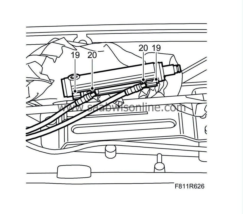
| 19. |
Remove the hydraulic line retaining clips by pulling them out.
|
|
| 20. |
Pull out the hydraulic lines from the hydraulic cylinder and remove the hydraulic cylinder.
|
|
| 21. |
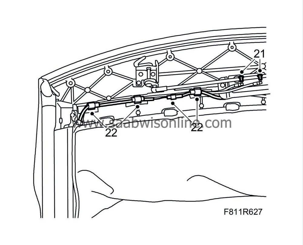
Plug the hydraulic lines to prevent oil from spilling on the roof upholstery.
|
|
| 22. |
Unplug the connector and cut off the cable ties; thread the hydraulic lines and the wiring harness out from the first bow.
|
|
| 23. |
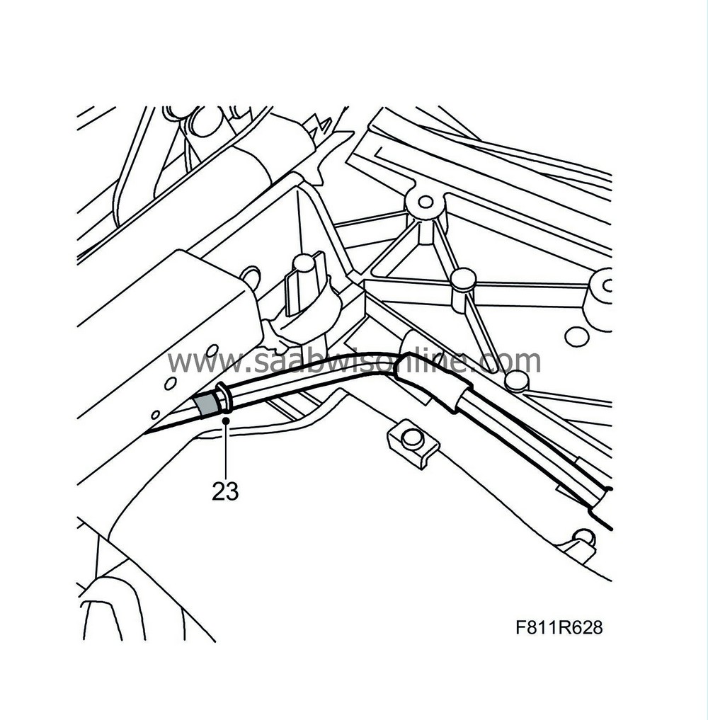
Cut off the cable ties securing the lines.
|
|
| 24. |
Close the soft top manually.
|
|
| 25. |
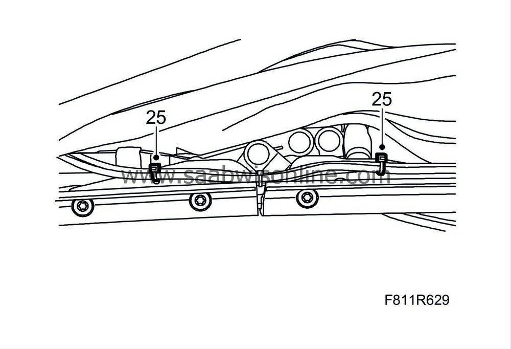
Remove the cable tie.
|
|
| 26. |
Remove the
soft top storage
.
|
|
| 28. |
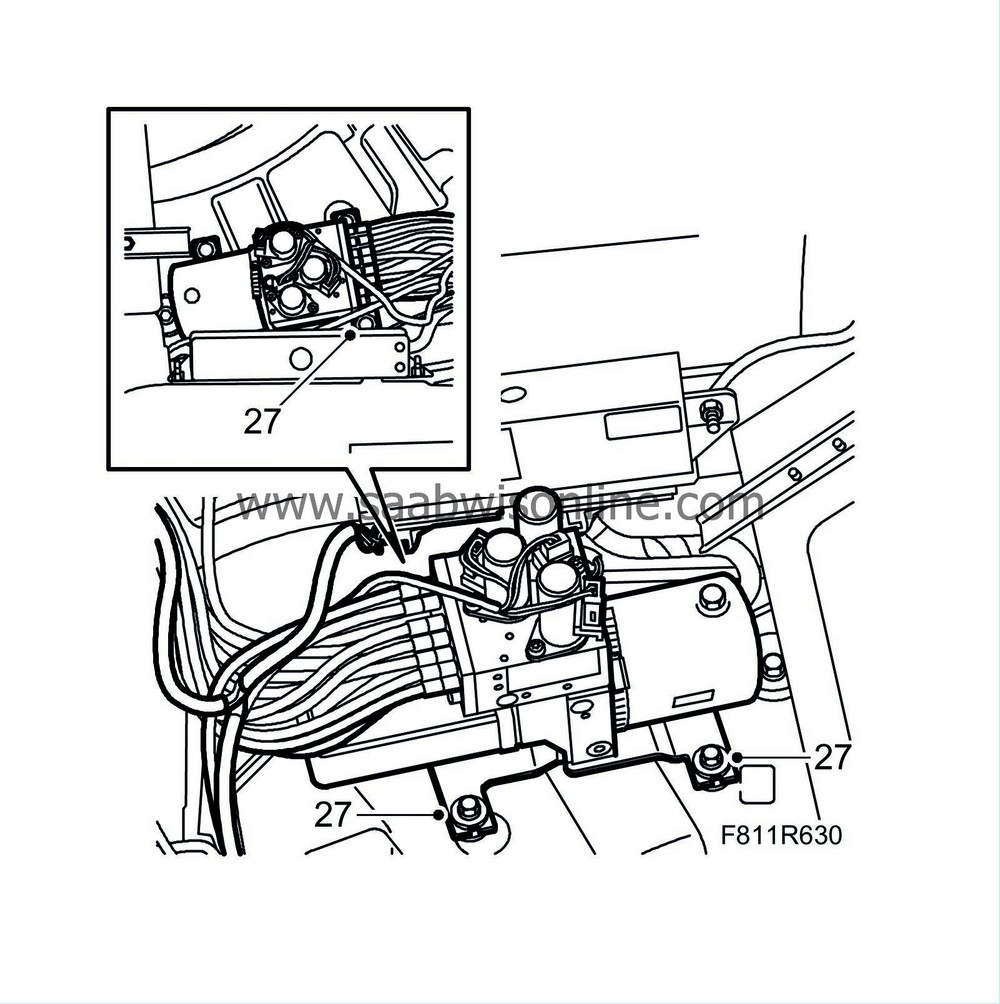
Position a cloth under the hydraulic unit to catch any hydraulic oil that may run out.
|
|
| 29. |
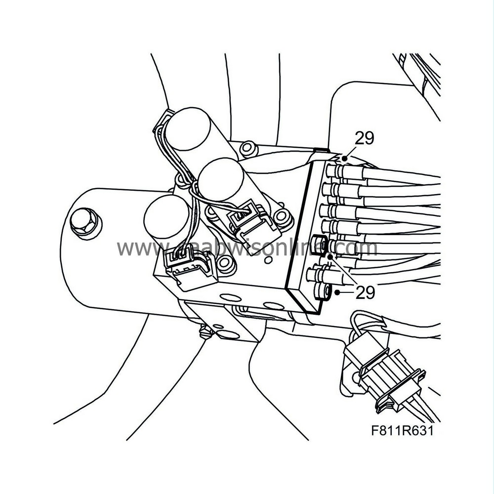
Remove the attaching plate together with the hydraulic lines from the hydraulic unit.
|
||||||||||
| 30. |
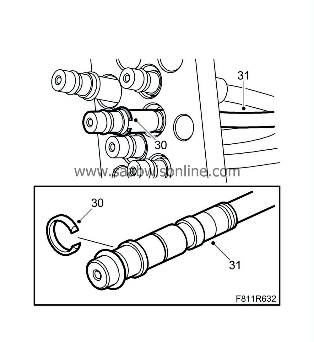
Remove the circlip from the connecting section of the hydraulic lines (no. 65 and 66) using a small screwdriver.
|
|
| 31. |
Pull the hydraulic lines out from the attaching plate.
|
|
| 32. |
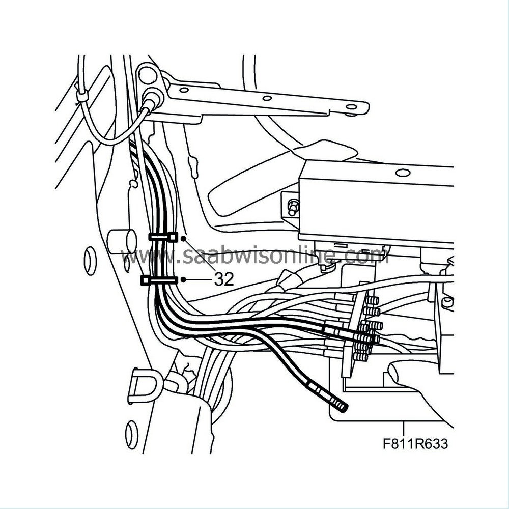
Remove the cable tie.
|
|
| 33. |
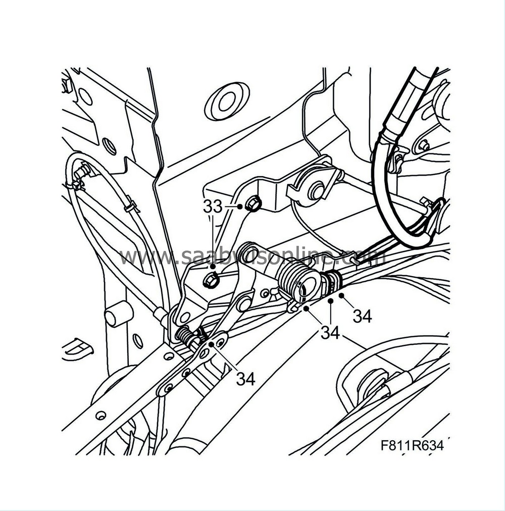
Detach the soft top storage hinge.
|
|
| 34. |
Remove the cable ties and open the hydraulic lines' brackets.
|
|
| 35. |
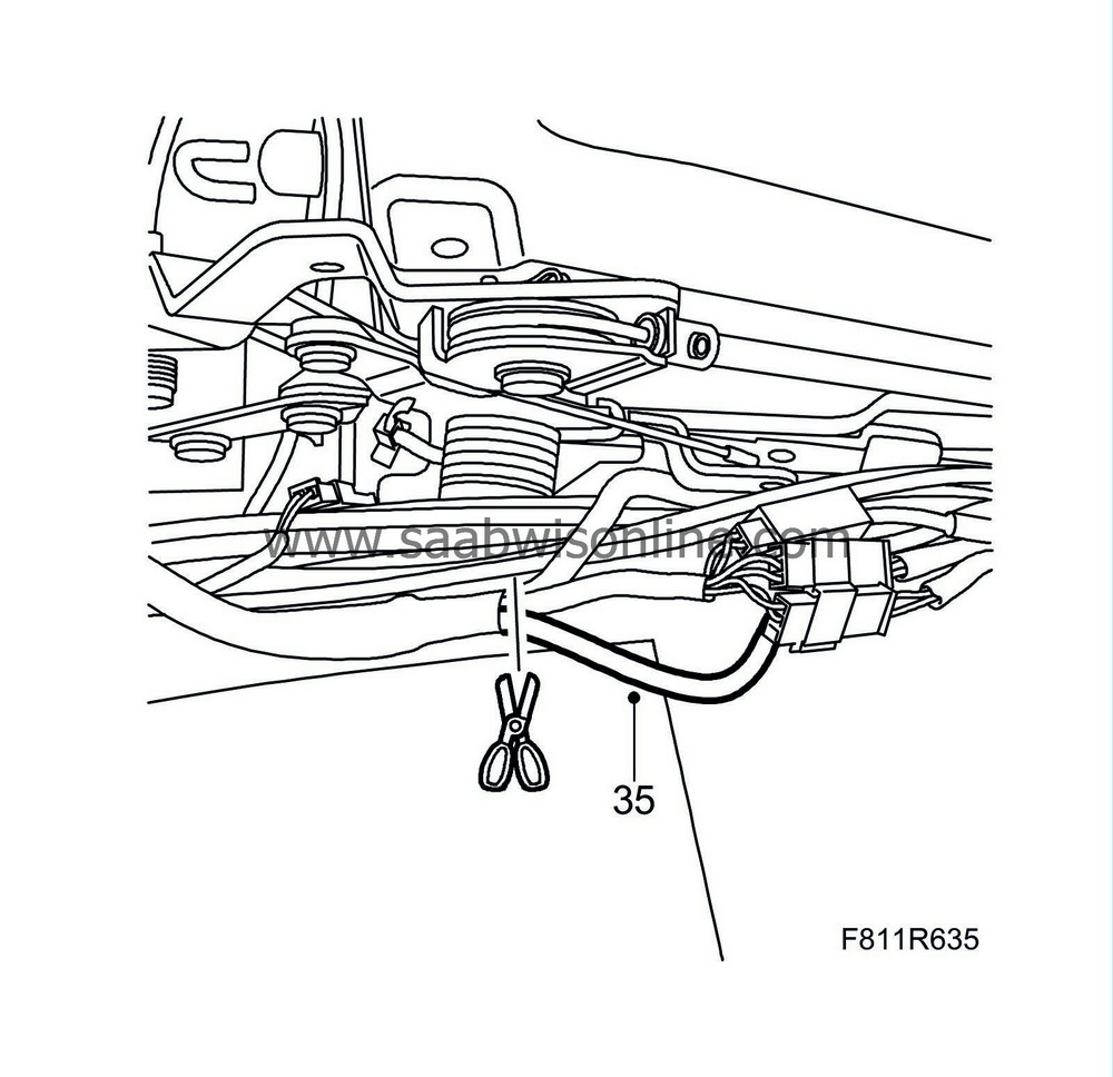
Lift up the line assembly. Locate the electrical cables from the first bow's position sensor and cut them off close to the wiring harness taping.
|
|
| 36. |
Unplug the connector (blue) from the control module.
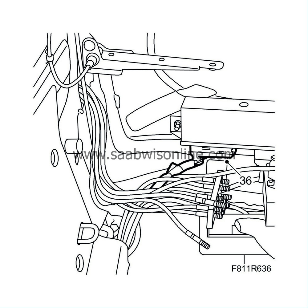
|
||||||||||
| 37. |
Separate the connector.
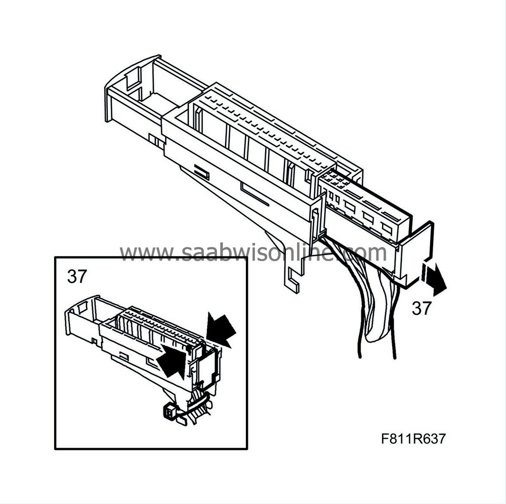
|
|
| 38. |
Remove the tape close to the connector so that the wires are exposed.
|
|
| 39. |
Extract sleeve 21 (brown) and sleeve 12 (black).
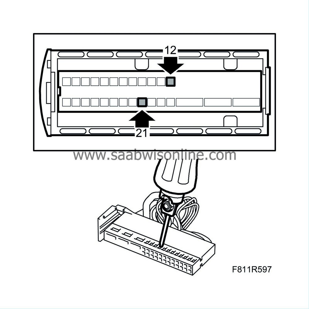
|
|
| 40. |
Cut off the extracted and exposed wires close to the tape.
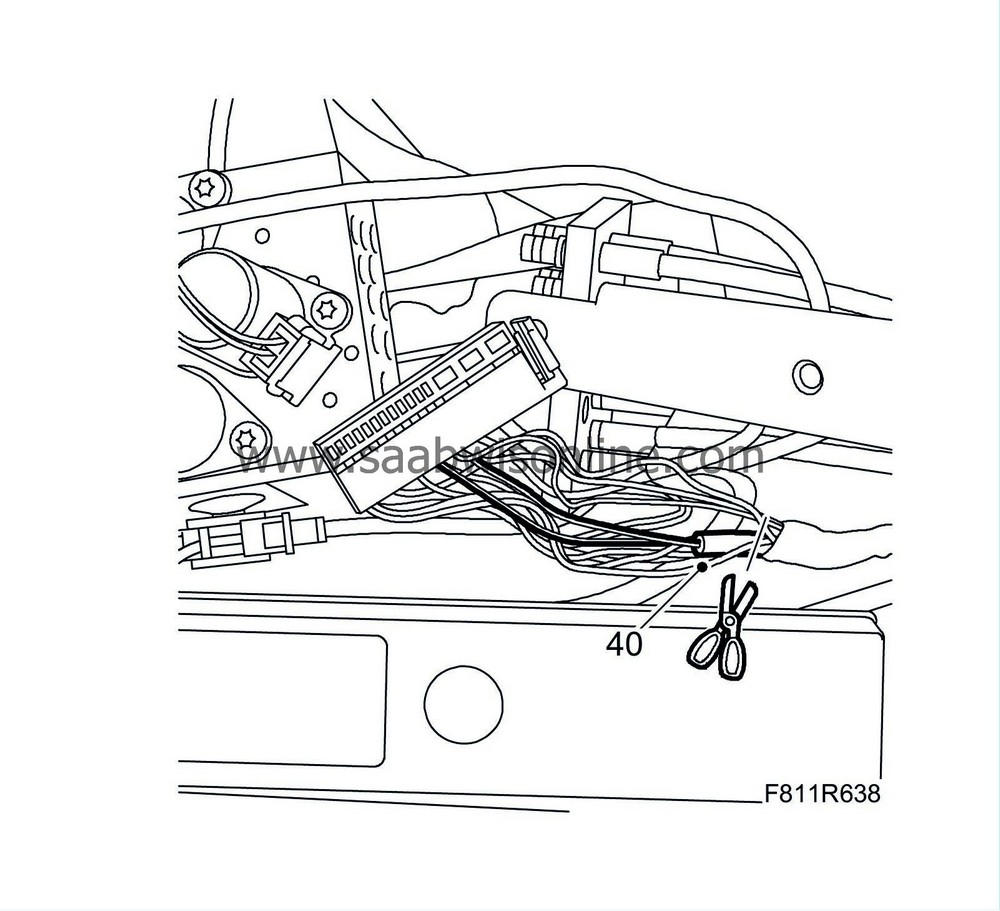
|
|
| 41. |
Note down the routing and attachment points for the wires.
|
|
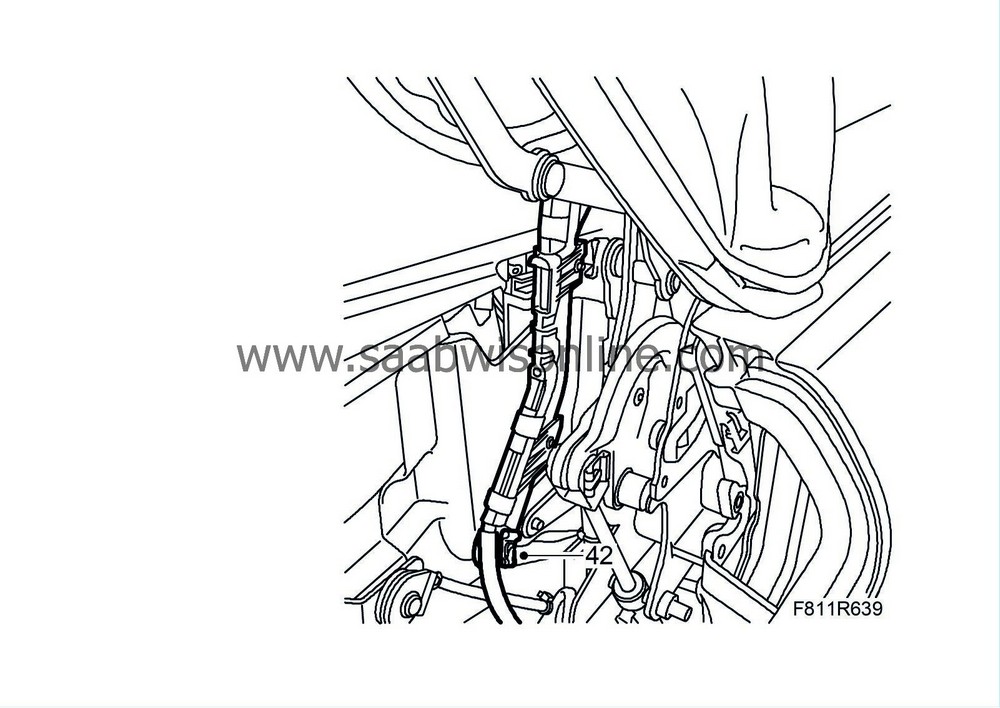
| 42. |
Remove the clip.
|
|
| 43. |
Cars up to and including VIN 46001629:
Remove the pop rivets and remove the cable duct from the hinge.
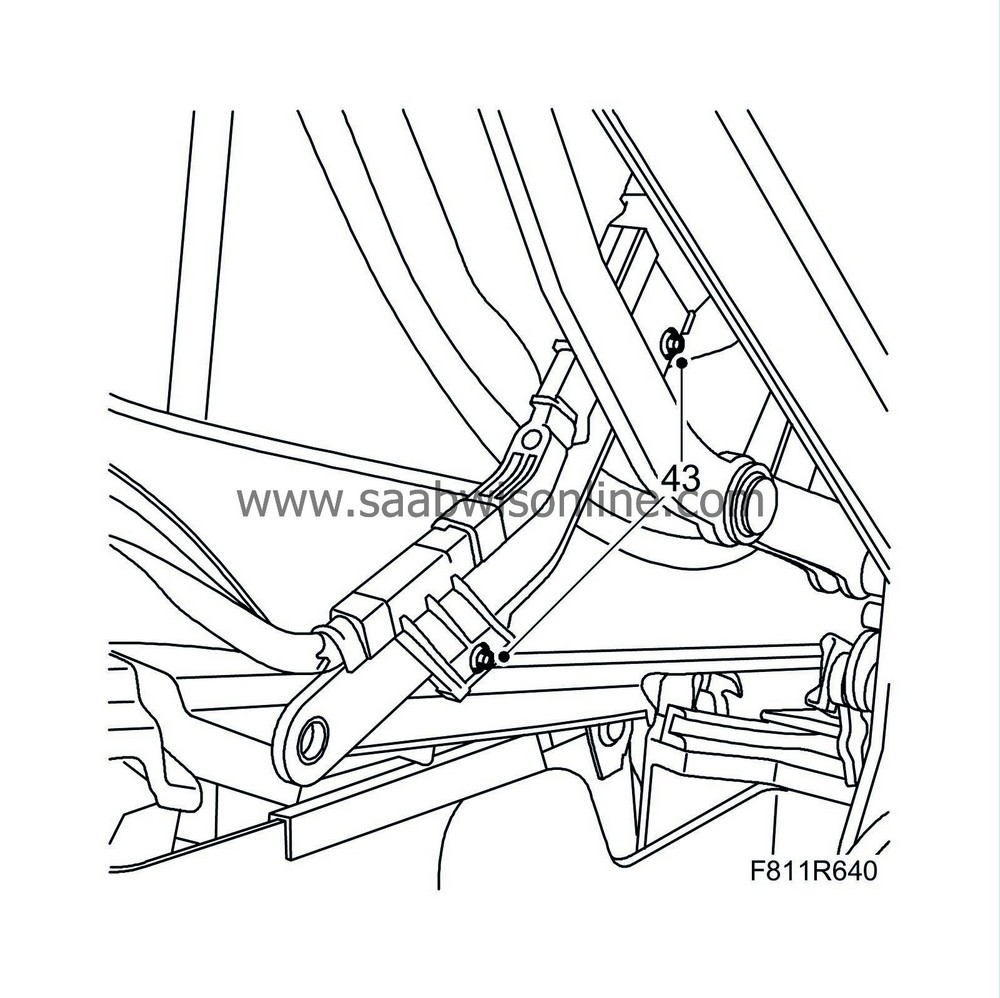
Cars from and including VIN 46001630: Remove the clips and remove the cable duct from the hinge. 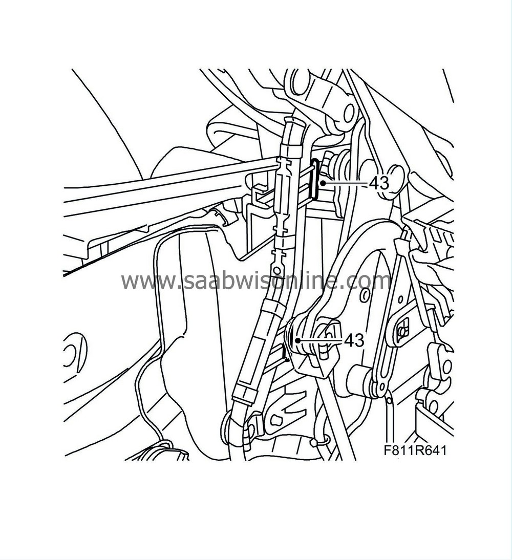
|
|
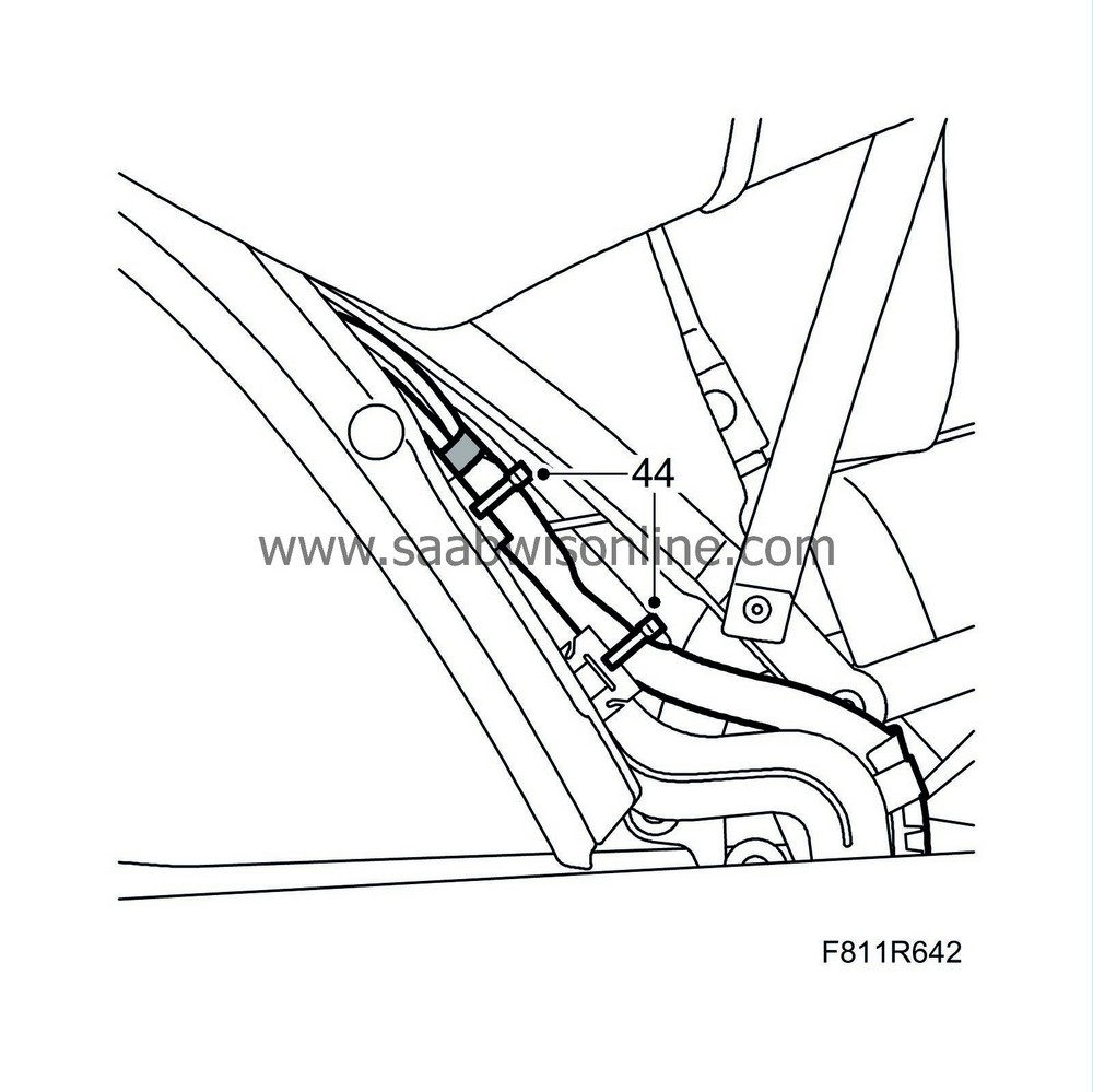
| 44. |
Detach the right-hand corner of the headlining and cut off the cable ties holding the cables to the metal clips.
|
|
| 45. |
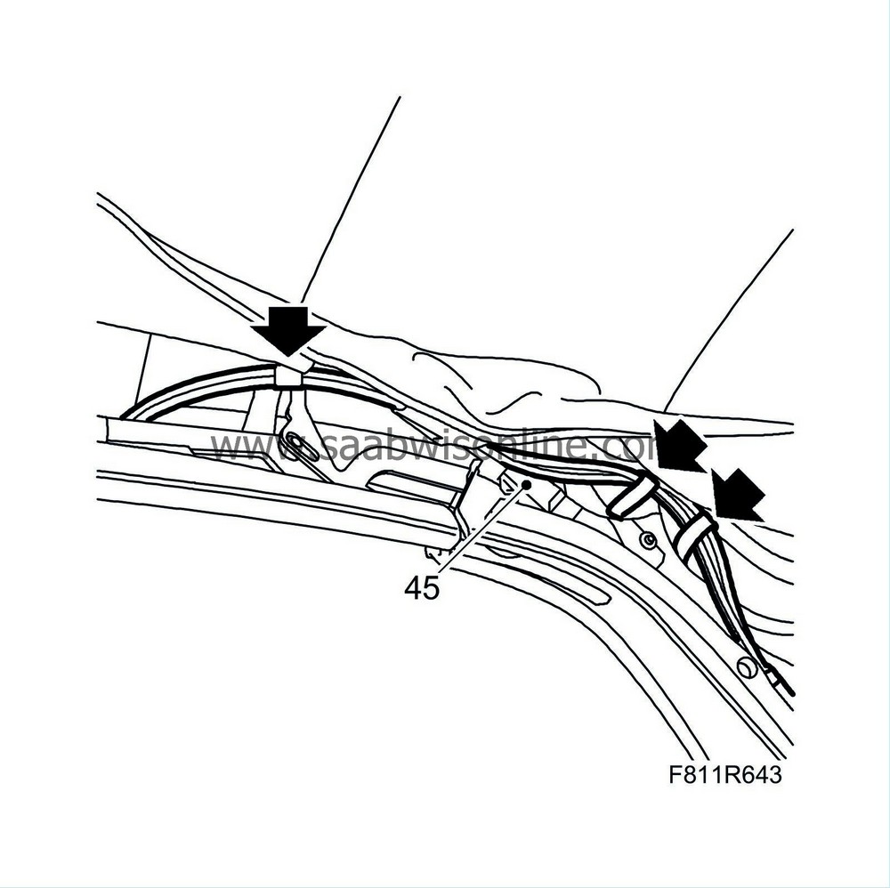
Carefully thread the line assembly backward from the soft top eyes.
|
|
| To fit |
| 1. |
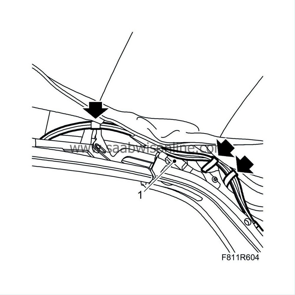
Carefully thread the lines through the soft top eyes.
|
||||||||||
| 2. |
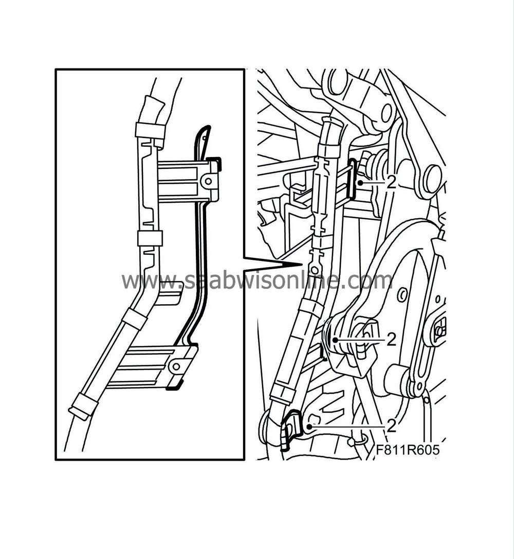
Secure the cable duct to the hinge with clips and refit the hinge's metal clips.
|
|
| 3. |
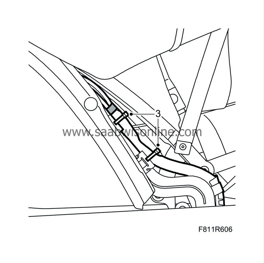
Fit chafe protection tape and secure the lines with new cable ties in the metal clips.
|
|
| 4. |
Fit the headlining right-hand corner.
|
|
| 5. |
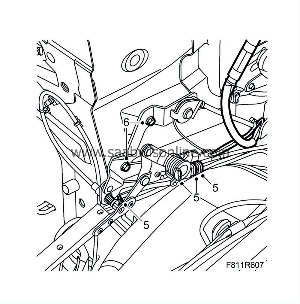
Fit the lines in place and secure them with new cable ties.
|
|
| 6. |
Fit the soft top storage hinge.
|
|
| 7. |
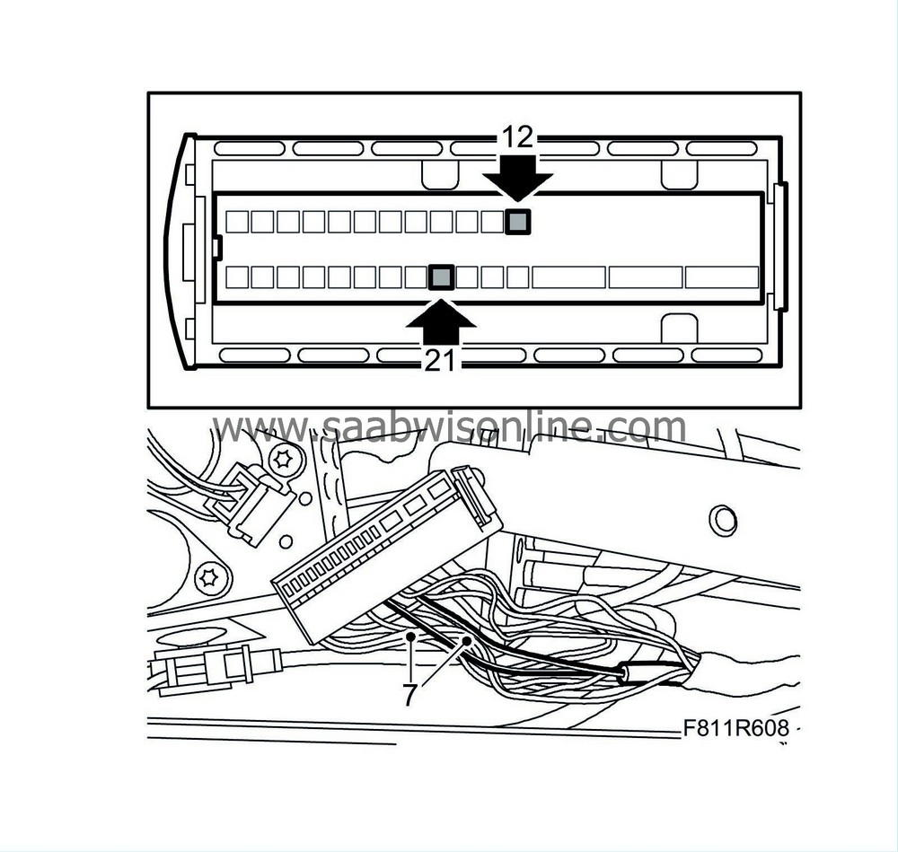
Fit sleeve 21 (brown) and sleeve 12 (black) in the connector.
|
|
| 8. |
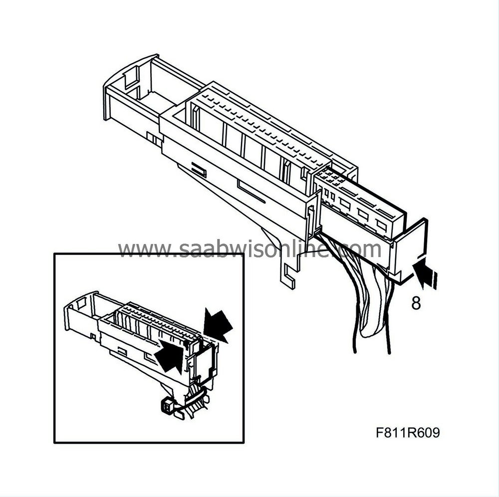
Plug the connector together.
|
|
| 9. |
Tape the exposed wires close to the connector.
|
|
| 10. |
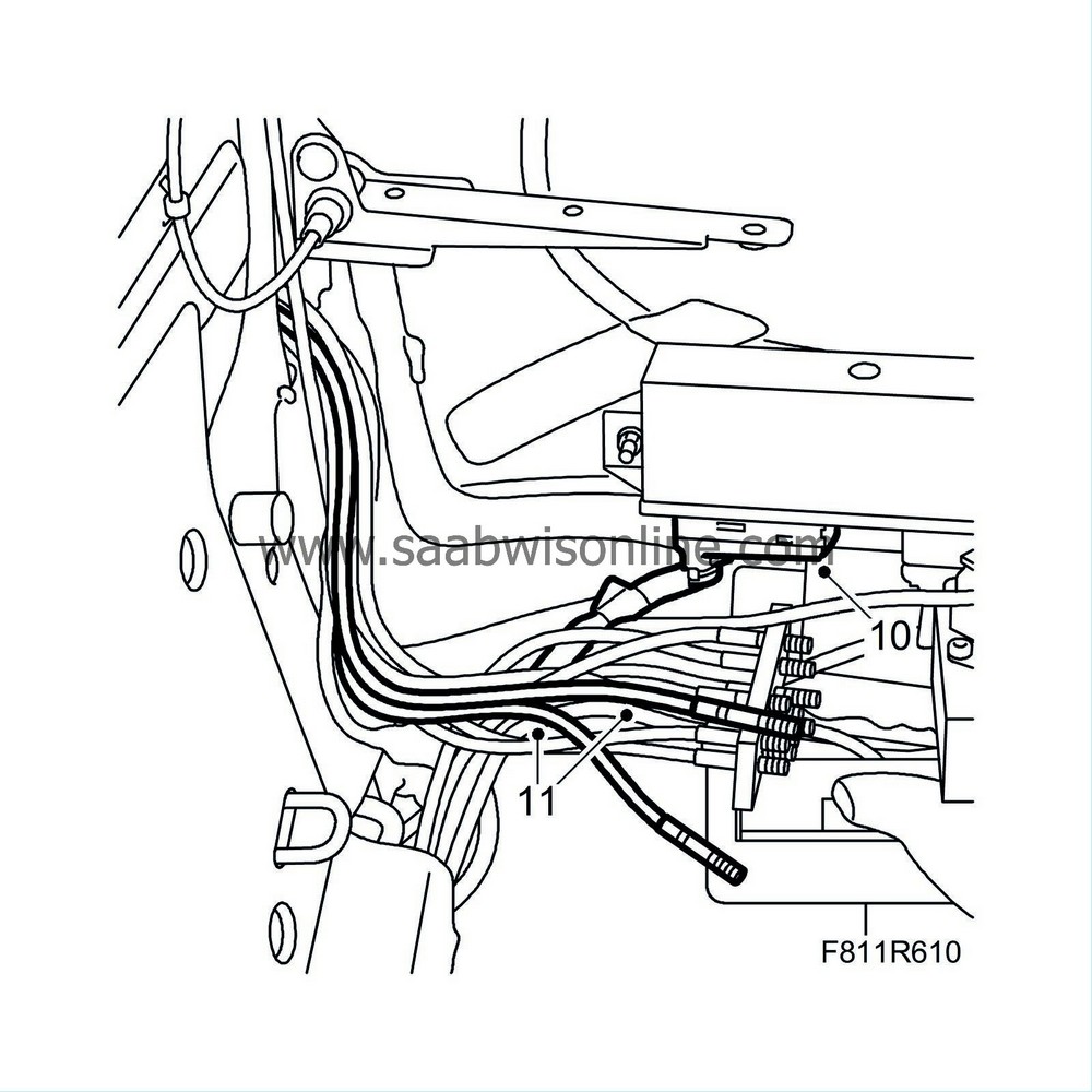
Plug the connector into the control module.
|
||||||||||
| 11. |
Insert the new hydraulic lines in the attaching plate in position no. 65 and 66.
|
|
| 12. |
Fit new circlips to the two new hydraulic lines:
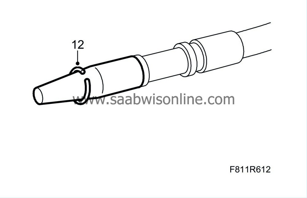
|
|
| - |
Press
82 93 854 Fitting tool, hydraulic line
over the hydraulic line connection.
|
| - |
Place the circlip on the taper of the special tool. Press it over the flange on the line.
|
| 13. |
Fit new O-rings on the new hydraulic lines:
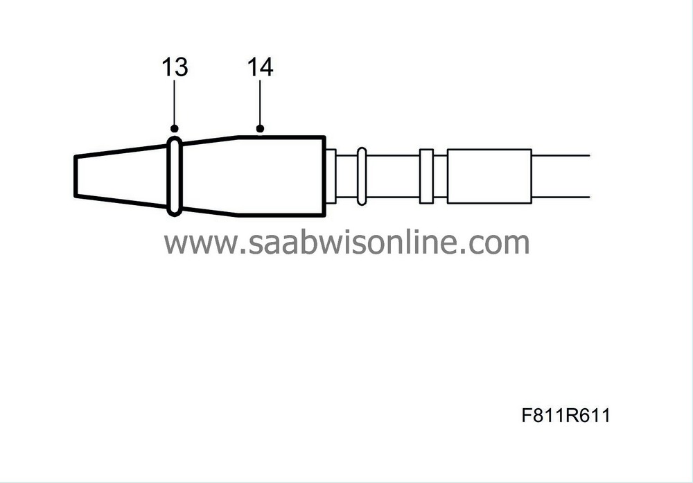
|
|
| - |
Press
82 93 854 Fitting tool, hydraulic line
over the hydraulic line connection.
|
| - |
Fit the O-ring on the special tool's cone and fit the O-ring on the hydraulic line.
|
| 14. |
Remove the special tool.
|
|
| 15. |
Place the attaching plate together with the hydraulic lines in mounting position.
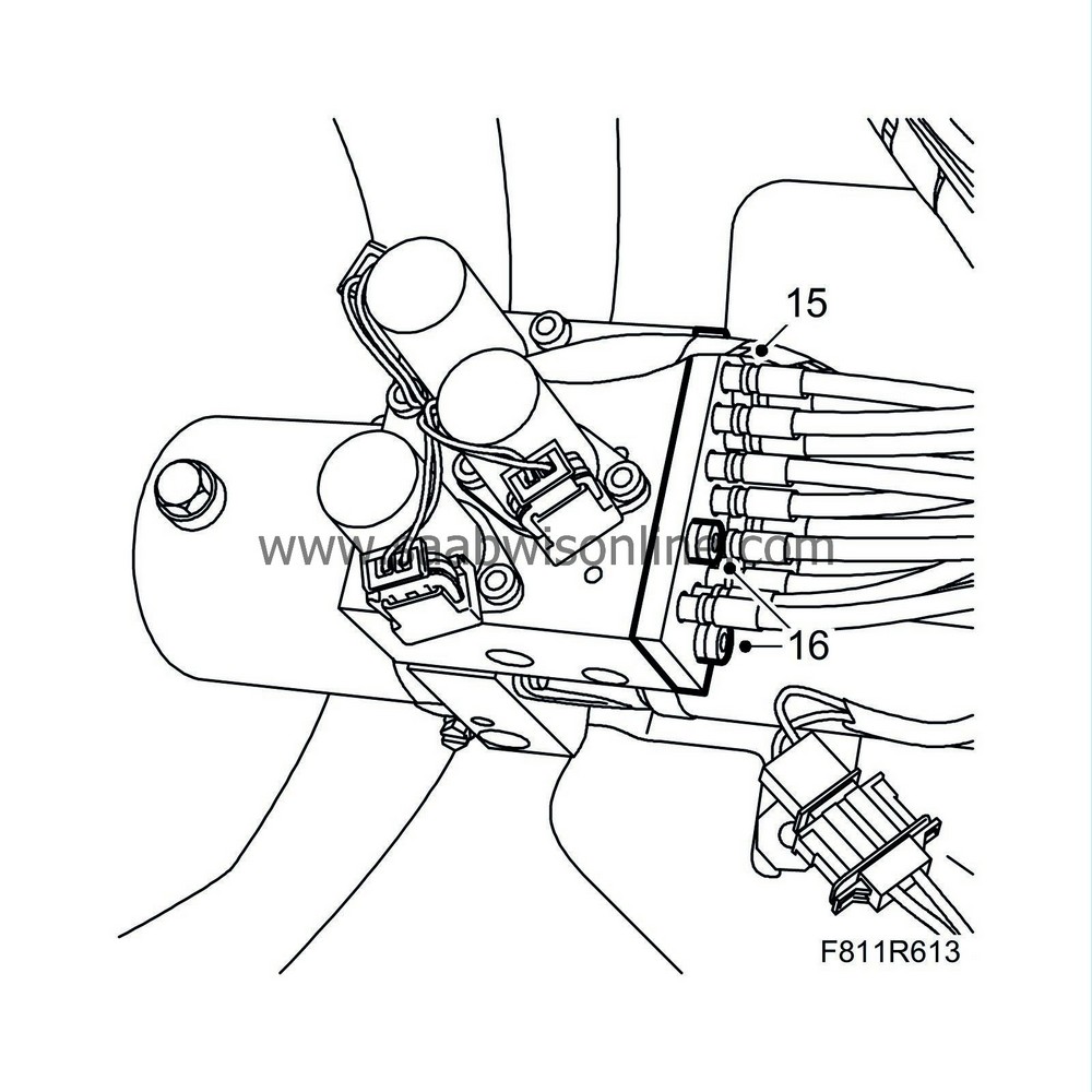
|
|
| 16. |
Fit and tighten the bolts for the hydraulic line attaching plate.
|
|
| 17. |
Wipe away any spilled oil.
|
|
| 18. |
Align the hydraulic unit in the fitting position and fit the hydraulic unit's nuts.
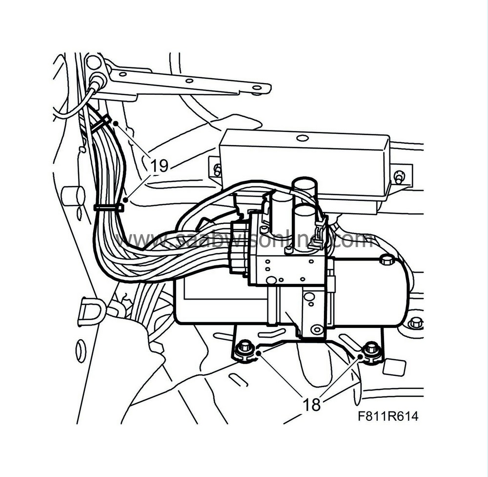
|
|
| 19. |
Secure the lines with cable ties.
|
|
| 20. |
Fit the
soft top storage
.
|
|
| 21. |
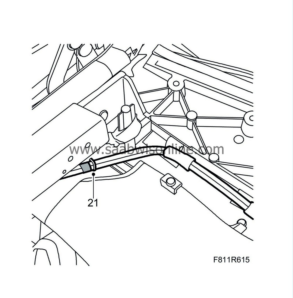
Plug in the connector and secure the lines with cable ties.
|
|
| 22. |
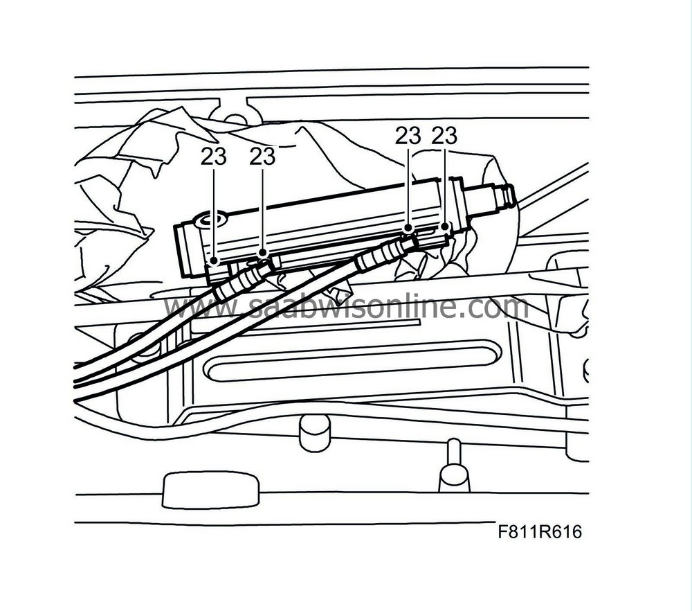
Replace the O-rings at the hydraulic cylinder's connections with new ones.
|
|
| 23. |
Fit the hydraulic lines on the hydraulic cylinder by pressing them in. Take care so as not to damage the seal.
|
|
| 24. |
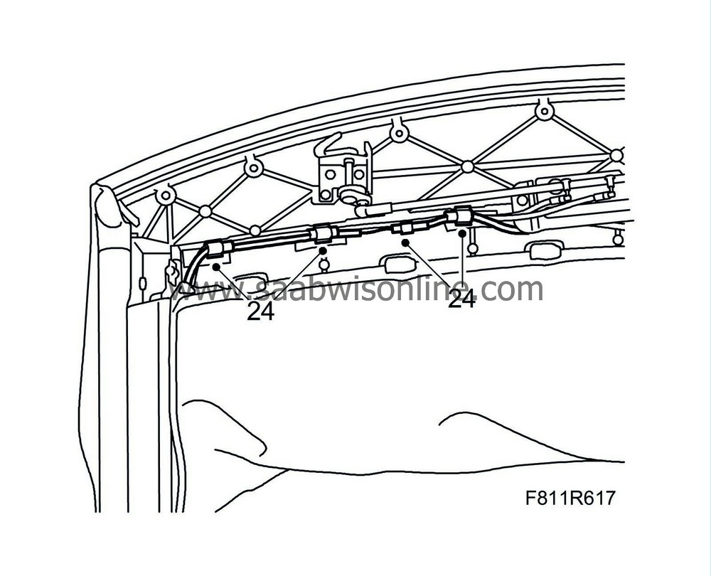
Fit the chafe protection tape on the line assembly and fit the line assembly clips.
|
|
| 25. |
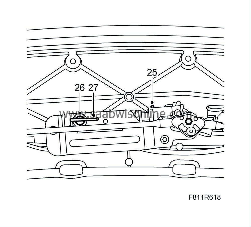
Put the hydraulic cylinder in mounting position. Fit the clip to the hydraulic cylinder piston rod.
|
|
| 26. |
Fit the fastening pin to the hydraulic cylinder.
|
|
| 27. |
Fit the cable lock to the fastening pin.
|
|
| 28. |
Turn the lock hooks to open them.
|
|
| 29. |
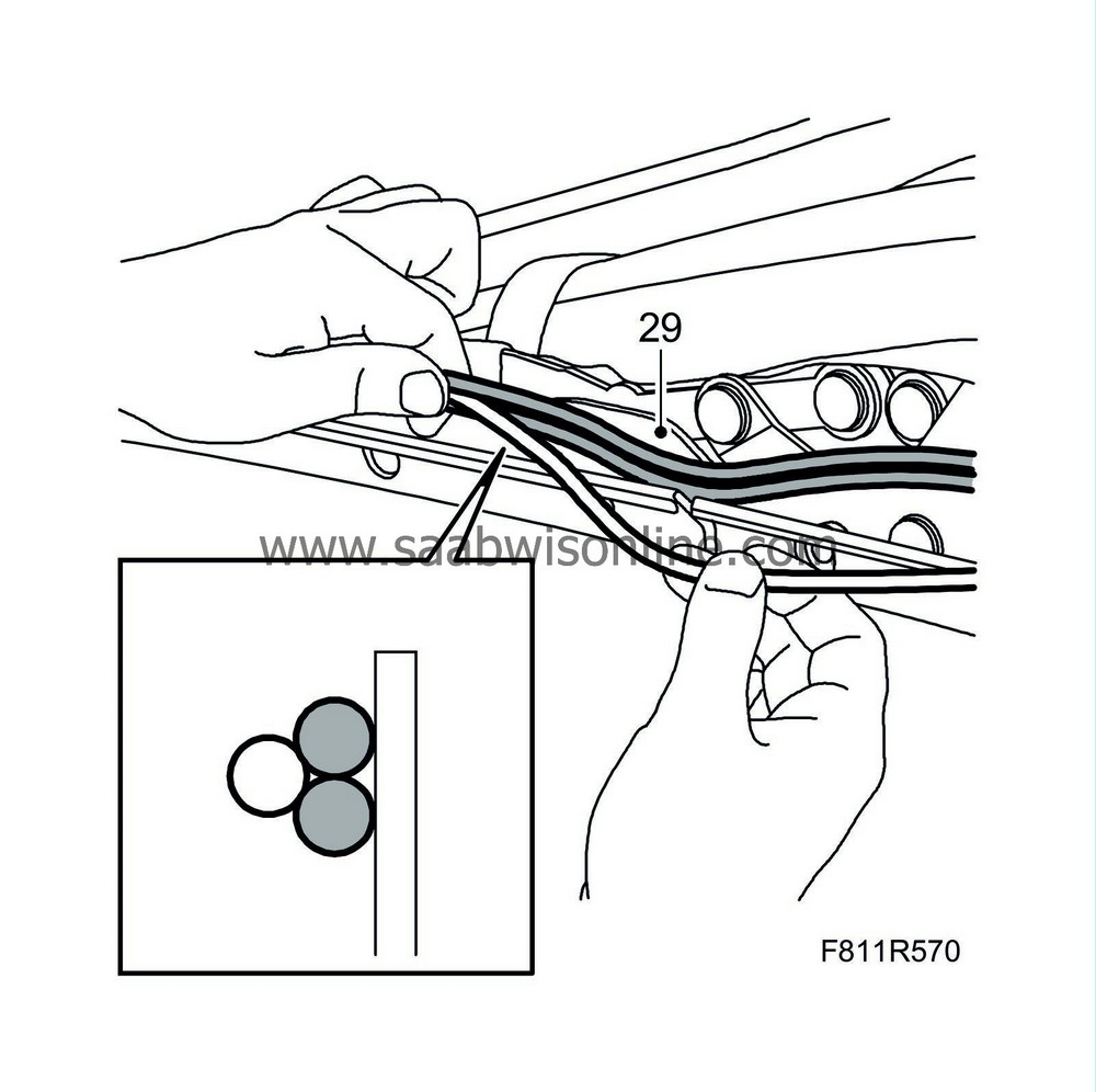
Untwist the line assembly and position the two hydraulic lines (grey) closest to the brackets with the electrical cable (white) on the outside of the hydraulic lines. The line assembly must be shaped like a triangle with the electrical cable on the outside, see illustration.
|
|||||||
| 30. |
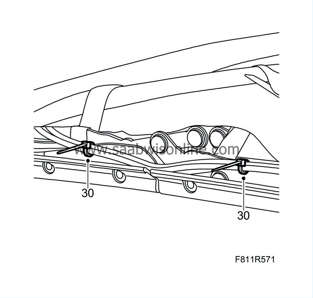
Secure the line assembly in the brackets with cable ties; tighten loosely. Fit the cable ties so that their heads are located uppermost on top of the line assembly.
|
|
| 31. |
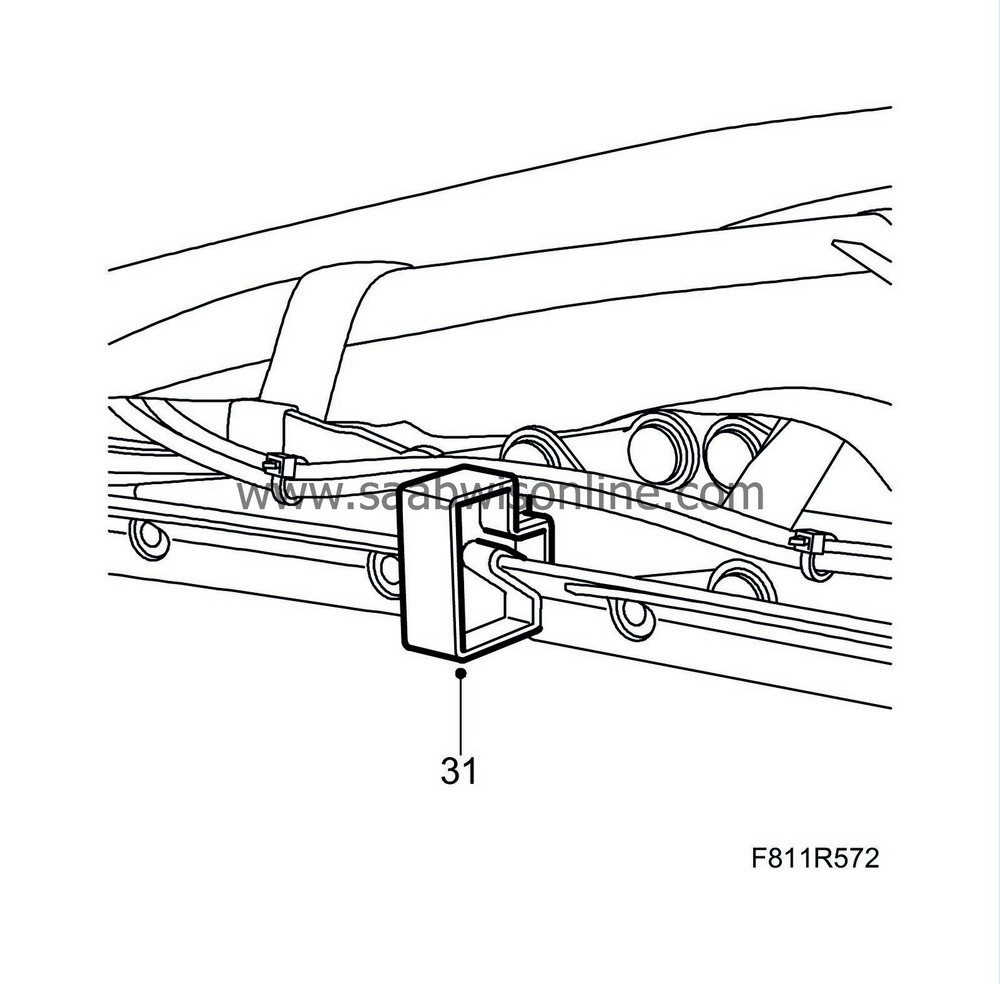
Fit
12 765 358 Fitting tool, CV
and position the line assembly on the top of the tool.
|
|
| 32. |
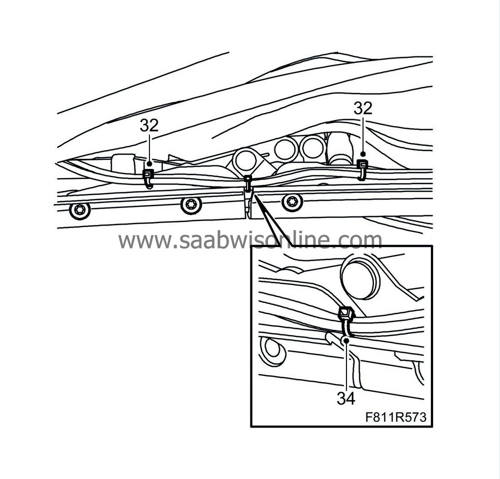
Tighten the cable ties and cut off any excess.
|
|
| 33. |
Remove the fitting tool.
|
|
| 34. |
Fit a small cable tie in the position between the centre and front rail.
|
|
| 35. |
Operate the soft top to its centre position; the soft top first bow must point straight up.
|
|||||||||
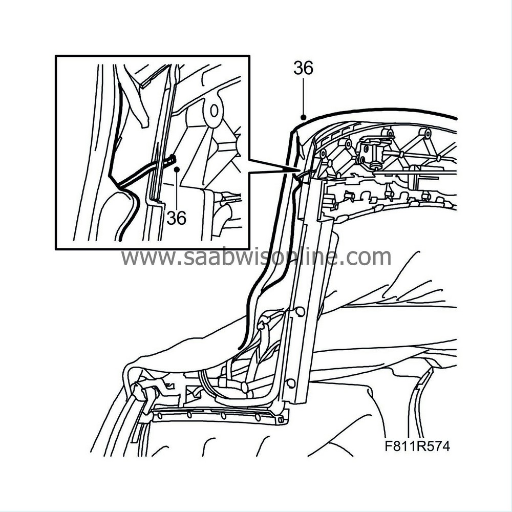
| 36. |
Fit the outer roof on the right-hand side of the first bow.
|
|
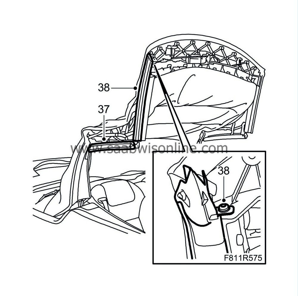
| 37. |
Fit the centre rail seal.
|
|
| 38. |
Fit the screw and the seal to the front rail.
|
|
| 39. |
Open the soft top and leave the soft top cover open.
|
|
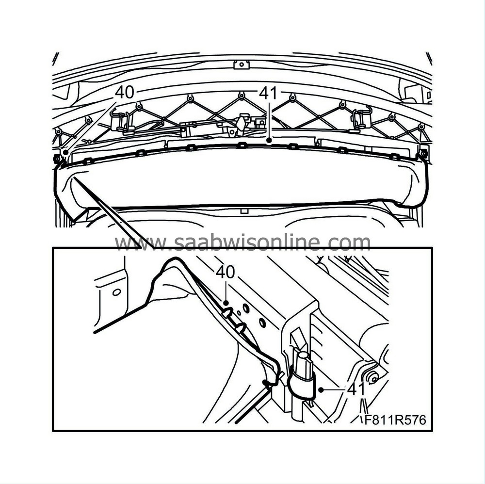
| 40. |
Fit the headlining plastic plugs and hook in the outer roof attachment eye on the right-hand side of the first bow.
|
|
| 41. |
Fit the headlining attachment eyes to the first bow on the right-hand side.
|
|
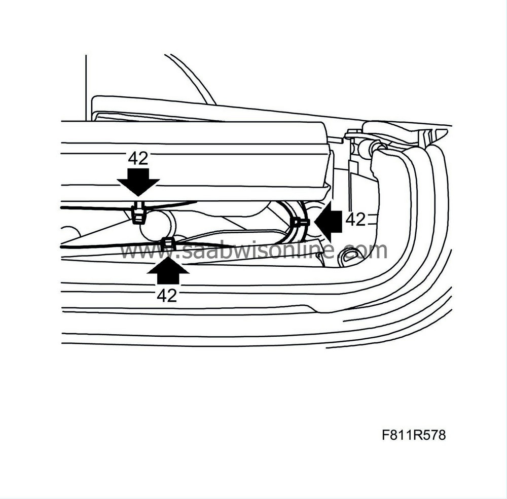
| 42. |
Operate the soft top to check that the line assembly does not get trapped or twist.
|
|
| 43. |
Operate the soft top for 5 complete cycles in order to bleed the system and check the function. Check that the lines are positioned correctly and that there is no risk of them becoming trapped in the hinges.
|
|
| 44. |
After hydraulic line replacement:
Fill oil in the reservoir up to the MAX mark. See
Checking/filling oil
.
|
|
| 45. |
After hydraulic line replacement:
Check that there is no leakage of oil at any point.
|
|
| 46. |
Open the soft top and leave the soft top cover open.
|
|
| 47. |
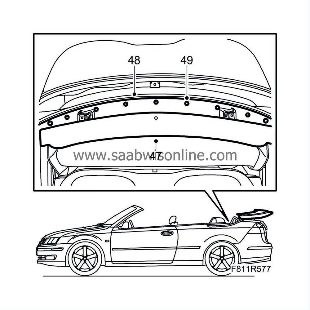
Fit the trim.
|
|
| 48. |
Fit the mounting plate with the clips.
|
|
| 49. |
Fit the clips' centre pins to the mounting plate.
|
|
| 50. |
Raise the soft top fully.
|
|
| 51. |
Connect the diagnostics tool and erase any diagnostic trouble code.
|
|

 Warning
