Test readings, control module connections
|
|
Test readings, control module connections
|
 The following pages contain readings and instructions for measuring signals and levels for SPA (Saab Parking Assistance).
|
•
|
Note the test conditions and use common sense when assessing the test result.
|
|
•
|
The specified readings are with the ignition ON unless stated otherwise.
|
|
•
|
First check that the control module has a power supply and is grounded.
|
|
•
|
Then check all sensor inputs and signals from other systems.
|
|
•
|
Finally, check the control module outputs. Remember that these readings are not an indication that the actuator is in working order.
|
|
•
|
If a reading is not OK, consult the wiring diagram to trace the leads, connectors or components which should be checked more thoroughly.
|
|
•
|
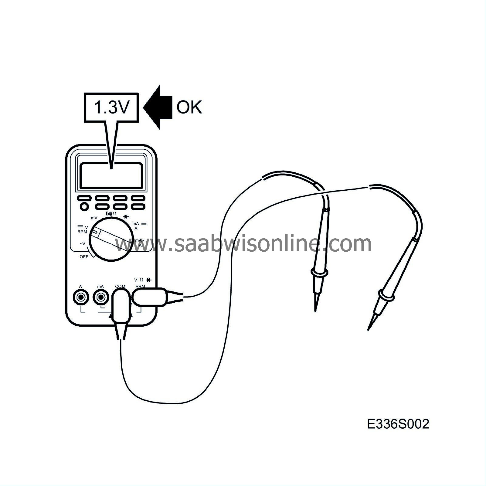
Specified values concern a calibrated Fluke 88/97.
|
|
•
|
Readings % (+) and ms (+) indicate the signal pulse ratio and pulse width respectively. A test instrument with pulse ratio and pulse width measurement must be used. The sign indicates a positive trigger pulse, TRIG+.
|
|
Pin
|
Component/
function
|
In/Out
|
Test conditions
|
Across
|
Test reading
|
|
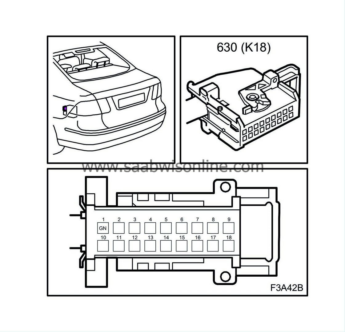
1
|
I-BUS
|
In/Out
|
Ignition ON
|
1 - B-
|
2.5 V
|
|
2-18
|
No connection
|
|
|
|
|
|
Pin
|
Component/
function
|
In/Out
|
Test conditions
|
Across
|
Test reading
|
|
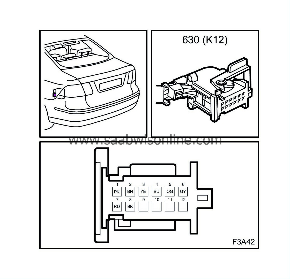
1
|
Voltage/sensor
|
Out
|
Ignition ON
|
1 - 2
|
B+
|
|
2
|
Ground/sensor
|
Out
|
Ignition ON
|
B+ - 2
2 - B-
|
B+
<0.5 V
|
|
3
|
Right outer sensor, communication
|
In/Out
|
Ignition ON
|
1 - 3
3 - 2
|
8V
95-105 kΩ
|
|
4
|
Centre right sensor, communication
|
In/Out
|
Ignition ON
|
1 - 4
4 - 2
|
8V
95-105 kΩ
|
|
5
|
Centre left sensor, communication
|
In/Out
|
Ignition ON
|
1 - 5
5 - 2
|
8V
95-105 kΩ
|
|
6
|
Left outer sensor, communication
|
In/Out
|
Ignition ON
|
1 - 6
6 - 2
|
8V
95-105 kΩ
|
|
7
|
Battery voltage +30
|
In
|
Ignition ON
|
7 - 8
B+ - 8
|
B+
B+
|
|
8
|
Ground
|
In
|
Ignition ON
|
8 - B-
|
<0.5 V
|
|
9-12
|
No connection
|
|
|
|
|


