PRE-RELEASE
Injectors (206)
| Injectors (206) |
| To remove |
|
||||||||||||||||||||||
| 1. |
Reduce the fuel pressure by removing fuse no. 4 Underhood electric centre, Trionic T8 in the engine bay while the engine is running. Turn the ignition key to LOCK once the engine has stopped.
|
|
| 2. |
Fit the fuse again.
|
|
| 3. |
Remove the upper engine cover.
|
|
| 4. |
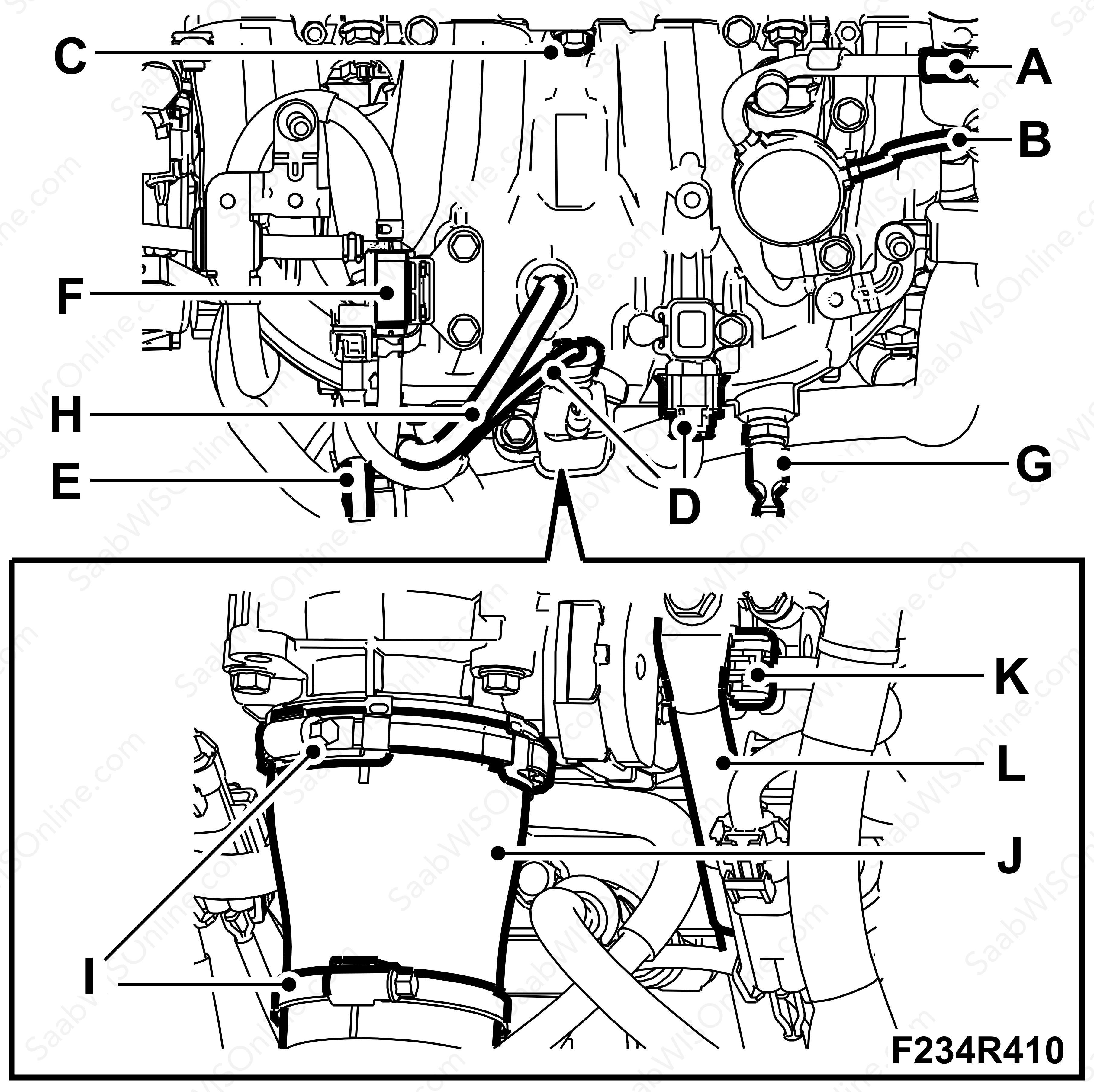
Remove the fuel pipe from the connection (A).

|
|
| 5. |
Plug the connection on the pipe.
|
|
| 6. |
Remove the fuel pipe (B) from the high pressure pump.
|
|
| 7. |
Remove the solenoid valve (F) from the intake manifold and move to the side.
|
|
| 8. |
Remove the vacuum hose from the connection (G) on the intake manifold.
|
|
| 9. |
Remove the connectors (D) from the intake manifold.
|
|
| 10. |
Undo the vacuum hose (H) from the intake manifold.
|
|
| 11. |
Remove the bracket to the dipstick (E).
|
|
| 12. |
Remove the hose clips (I) and remove the intake hose (J).
|
|
| 13. |
Remove the upper bracket to the stay (L) on the intake manifold and remove the connector (K) on the throttle body.
|
|
| 14. |
Remove the bolts (C) to the intake manifold and lift off the intake manifold.
|
|
| 15. |
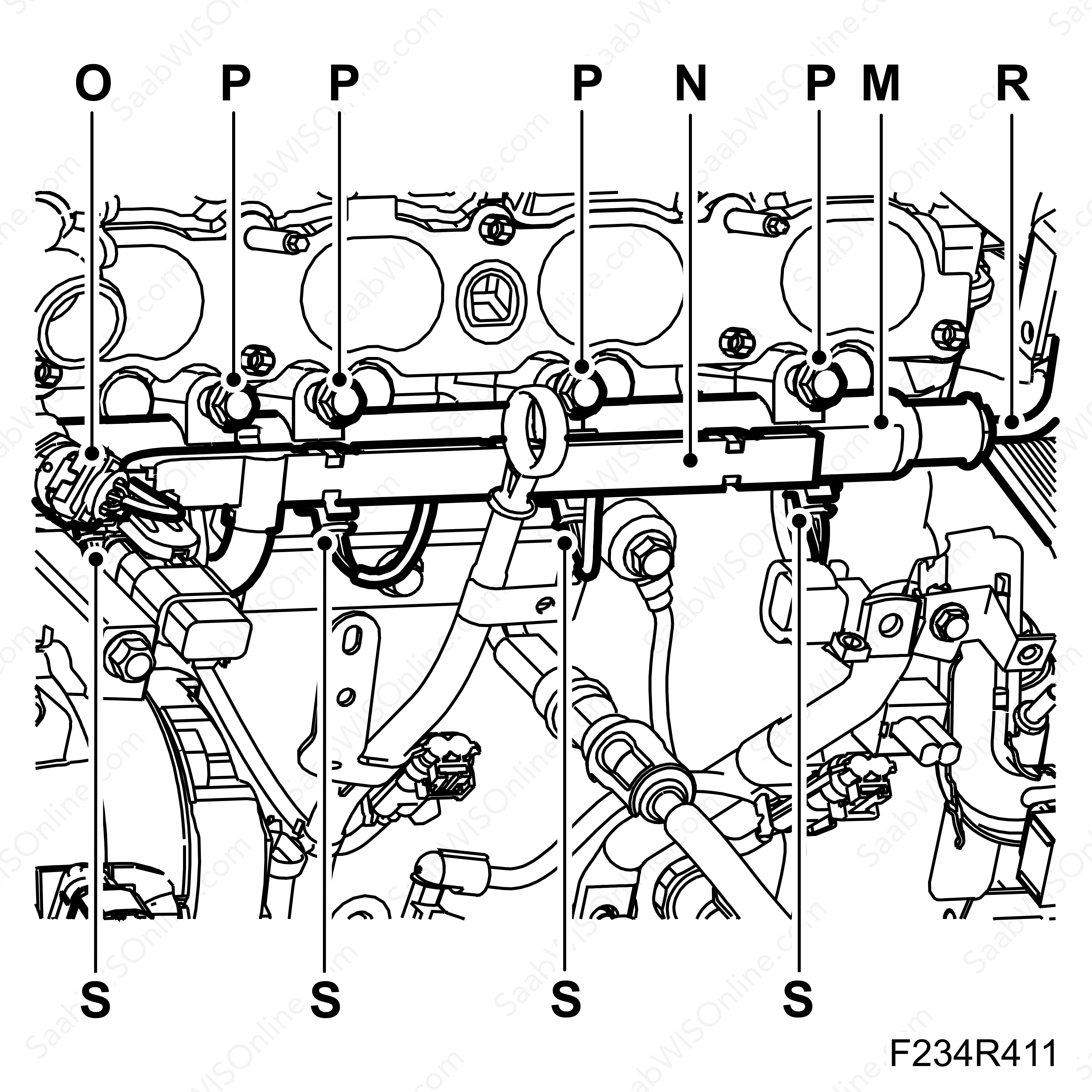
Remove the noise insulation for the injectors and undo the cable duct (N). Remove the connector (O) and the connectors (S) to the injectors.

|
|
| 16. |
Remove the bolts (P) and the pipe connection (R) to the rail (M). Lift off the rail and replace the nozzle.
|
|
| To fit |
| 1. |
Fit the injectors with NEW O-rings, lubricate sparingly with Vaseline.
|
|
| 2. |
Fit the injectors and fit the fuel rail (M) to the cylinder head.

|
|
| 3. |
Screw in the bolts (P). These have a specific tightening order, 1-4-2-3. First tighten bolt no. 1, the one on the far right of the illustration. Then tighten bolt no. 4, the one on the far left of the illustration. Then tighten bolt no. 2 and then bolt no. 3.
Tightening torque 25 Nm (18 lbf ft). |
|
| 4. |
Fit the pipe (R) to the fuel rail (M)
|
|
| 5. |
Fit the cable duct (N) and the connector (O). Connect the injectors' connectors (S) and make sure they are secure.
|
|
| 6. |
Fit the intake manifold with a NEW gasket and tighten the bolts (C).
Tightening torque 25 Nm (18 lbf ft) 
|
|
| 7. |
Fit the connector (K) to the throttle body and the stay (L) to the intake manifold.
|
|
| 8. |
Fit the intake hose (J) and tighten both hose clips (I).
|
|
| 9. |
Fit the bracket for the dipstick (E).
|
|
| 10. |
Fit the connectors (D) and connect the vacuum hose (H) to the intake manifold.
|
|
| 11. |
Fit the solenoid valve (F) to the intake manifold and connect the hose to (G).
|
|
| 12. |
Fit the pipe (B) and connect fuel supply to (A). Fix the pipe along the intake manifold and at the camshaft cover (B).
|
|
| 13. |
Connect an exhaust extractor. Start the engine and check for fuel leaks.
|
|
| 14. |
Switch off the engine.
|
|
| 15. |
Fit the upper engine cover (A).
|
|

 Warning

