PRE-RELEASE
Description of control system for evaporation emissions, E39
| Description of control system for evaporation emissions, E39 |
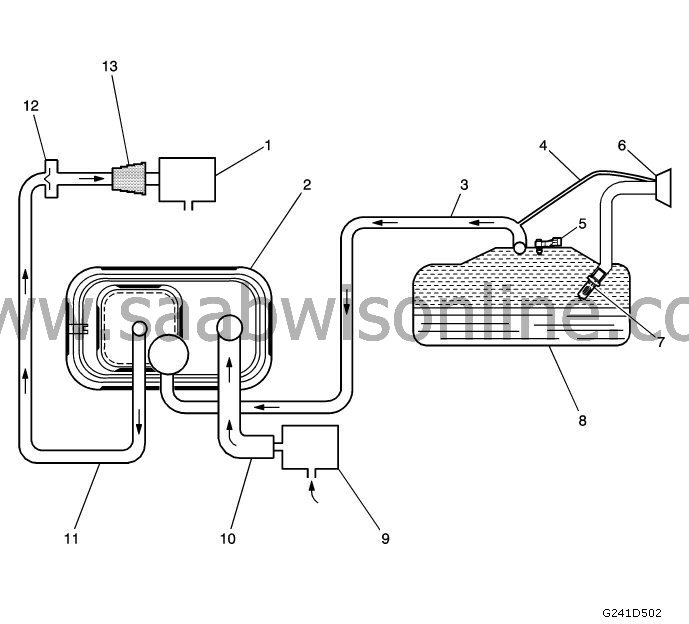
(1) Tank purge (EVAP) carbon filter purge solenoid valve
(2) EVAP reservoir
(3) EVAP condensation hose
(4) Return hose, fuel vapour
(5) Pressure sensor, fuel tank, variants with tank seal diagnosis
(6) Fuel filler cap
(7) Check valve, inlet, fuel filler pipe
(8) Fuel tank
(9) Vent valve, EVAP reservoir, variants with tank seal diagnosis
(10) Ventilation hose
(11) EVAP evacuation hose
(12) Check valve vent hose, turbocharged applications
(13) Hose coupling, EVAP carbon filter reservoir
| Function of the EVAP system |
The control system for evaporation emissions (EVAP) prevents fuel vapour getting into the atmosphere. Vapour from the fuel tank is vented due to the pressure in the tank via the vapour pipe to the EVAP reservoir. Carbon in the reservoir absorbs and stores the fuel vapour. Overpressure is vented out to the atmosphere via the ventilation hose and the carbon filter reservoir's solenoid valve.
The EVAP reservoir stores the fuel vapour until the engine is able to combust it. At an appropriate time, the engine control module (ECM) activates the EVAP reservoir's purge valve, which links the engine's vacuum to the EVAP reservoir.
When the normally open solenoid valve on the carbon filter reservoir* is OFF, fresh air is sucked in through the ventilation valve and the ventilation hose to the carbon filter reservoir. Fresh air is pulled through the carbon filter and bring with it fuel vapour from the carbon.
The mixture of air/fuel vapour continues via the EVAP drainage pipe and the purge valve to the intake manifold and is then consumed during normal combustion in the engine. The control module carried out a number of tests to determine whether the EVAP system is leaking or blocked.
*US with tank seal diagnosis only.
| Leak testing the vent valve (US with tank seal diagnosis only) |
If the vent valve does not seal correctly, fuel vapour may enter the engine at inappropriate times and cause driveability problems. The ECM tests this by switching the vent valve solenoid to OFF and the ventilation valve solenoid to ON, which closes the system. With the engine running, the ECM then monitors the fuel tank's pressure sensor for increased vacuum. The ECM registers a fault if a vacuum forms in the tank under these conditions.
| Major leak test |
This diagnosis creates a vacuum in the EVAP system. When activation criteria have been met, the control module requests the closure of the ventilation valve on the carbon filter reservoir, which is normally open, and the opening of the vent valve, which creates a vacuum in the EVAP system.
The ECM then monitors the voltage from the fuel tank's pressure sensor in order to confirm that the system is able to reach a predetermined vacuum level within a given time. If the vacuum level cannot be reached, this shows that there is a major leak in the EVAP system or a restriction in the vent route. The ECM registers a fault if it discovers a poorer vacuum level than expected under these conditions.
| Restriction test, carbon filter reservoir ventilation system |
If the ventilation system in the tank purge system is restricted, the fuel vapour cannot be purged from the carbon filter reservoir. The ECM investigates this by switching the purge valve solenoid to ON while the ventilation valve solenoid is switched to OFF. The ECM then monitors whether the fuel tank pressure sensor shows a vacuum increase. If the vacuum increases more than expected over a given time, the ECM registers a fault.
| Minor leak test |
The diagnosis for natural vacuum with the engine off is designed to locate minor leaks for the purge system (EVAP). The diagnosis for natural vacuum with the engine off monitors EVAP system pressure when the ignition is OFF. Due to this function, it may be entirely normal for the control module to be active for up to 40 minutes after the ignition has been switched OFF.
It is important to remember this if you are testing for leakage current in cars fitted with natural vacuum with the engine off.
When the car is driven, the temperature in the tank rises due to heat radiation from the exhaust system. Once the car has been parked up, the temperature continues to rise in the tank for a time, then it starts to drop. The diagnosis for natural vacuum with the engine off is dependent on this temperature change and a corresponding pressure change in the closed system in order to determine whether there is a leak in the EVAP system.
The diagnosis for natural vacuum with the engine off is designed to detect leaks as tiny as 0.51 mm (0.020 in.).
| EVAP system components |
The EVAP system consists of the following components:
Discharge valve, EVAP reservoir
The EVAP purge solenoid valve controls the flow of vapour from the EVAP system to the intake manifold. The discharge solenoid valve opens when it is ordered ON by the control module. This valve, which is normally closed, is pulse width modulated (PWM) by the control module for precise control of the flow of fuel vapour to the engine.This valve will also be open during parts of the EVAP tests with the engine running, which makes it possible for the engine vacuum to influence the EVAP system.
Check valve, vent hose
Turbocharged cars have a check valve in the vent hose between the EVAP system's solenoid valve and the carbon filter reservoir in order to prevent pressurisation of the EVAP system when the turbocharger charges. Note that the check valve prevents pressure testing for leaks in the EVAP system in the hose coupling at the carbon filter reservoir.EVAP reservoir
The reservoir is filled with carbon pellets which are used to absorb and store fuel vapour. Fuel vapour is stored in the reservoir until the control unit decides that vapour can be consumed as part of the engine's normal combustion process.Return hose, fuel vapour
It is necessary to have a line for fuel vapour between the fuel filler and the vapour hose to the carbon filter reservoir so that the car's self-diagnostic system can monitor the EVAP system. This also facilitates service diagnostics because it is possible to diagnose the entire EVAP system from both ends.Pressure sensor, fuel tank*
The fuel tank pressure sensor measures the difference between pressure/vacuum in the fuel tank and the ambient air pressure. The control unit supplies the fuel tank pressure sensor with a 5 V reference and earth. Depending on the car model, the sensor may be located in the vapour chamber at the top of the fuel tank, in the vapour hose between the the carbon filter reservoir and the tank, or on the carbon filter reservoir itself.The fuel tank pressure sensor emits a voltage signal back to the control unit. This signal may vary between 0.1 and 4.9 V. A high voltage from the fuel tank pressure sensor indicates a low pressure or vacuum in the fuel tank. A low voltage from the fuel tank pressure sensor indicates a high pressure in the fuel tank.
Check valve, fuel filler pipe
The check valve in the fuel filler pipe prevents overfilling when fuelling.Vent valve, EVAP reservoir*
The EVAP system's ventilation valve controls the flow of fresh air into the carbon filter reservoir. This valve is normally open. The ventilation valve is only closed when the ECM is testing the EVAP system.Fuel filler cap
The fuel filler cap is fitted with a seal and a reducing valve for vacuum.*US with tank seal diagnosis only
