PRE-RELEASE
Ignition system (320a-d), E39
| Ignition system (320a-d), E39 |
| Location |
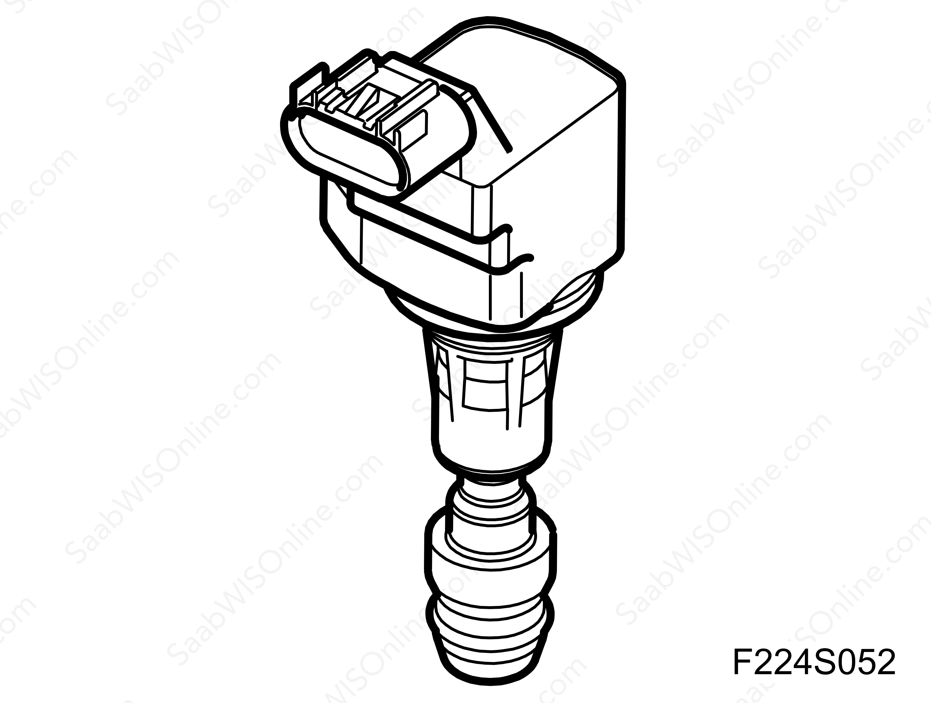
The ignition coils, individually ex hangable, are fitted above the spark plugs on each cylinder, fastened with a screw.
Ignition coil with integrated power stage, cyl 1 (320a), E39
Ignition coil with integrated power stage, cyl 2 (320b), E39
Ignition coil with integrated power stage, cyl 3 (320c), E39
Ignition coil with integrated power stage, cyl 4 (320d), E39
| Main task |
The ignition system generates the ignition spark and and measures combustion quality. It comprises four inductive ignition coils, one for each cylinder, with an integrated final stage.
| Type |
Ignition system with inductive ignition coils and integrated final stage.
The ignition system receives four ignition trigger signals from the ECM control module, E39 (590) and returns two combustion signals.

| Connection |
| Ignition system, cyl 1, 320a pin no | Signal type | Description |
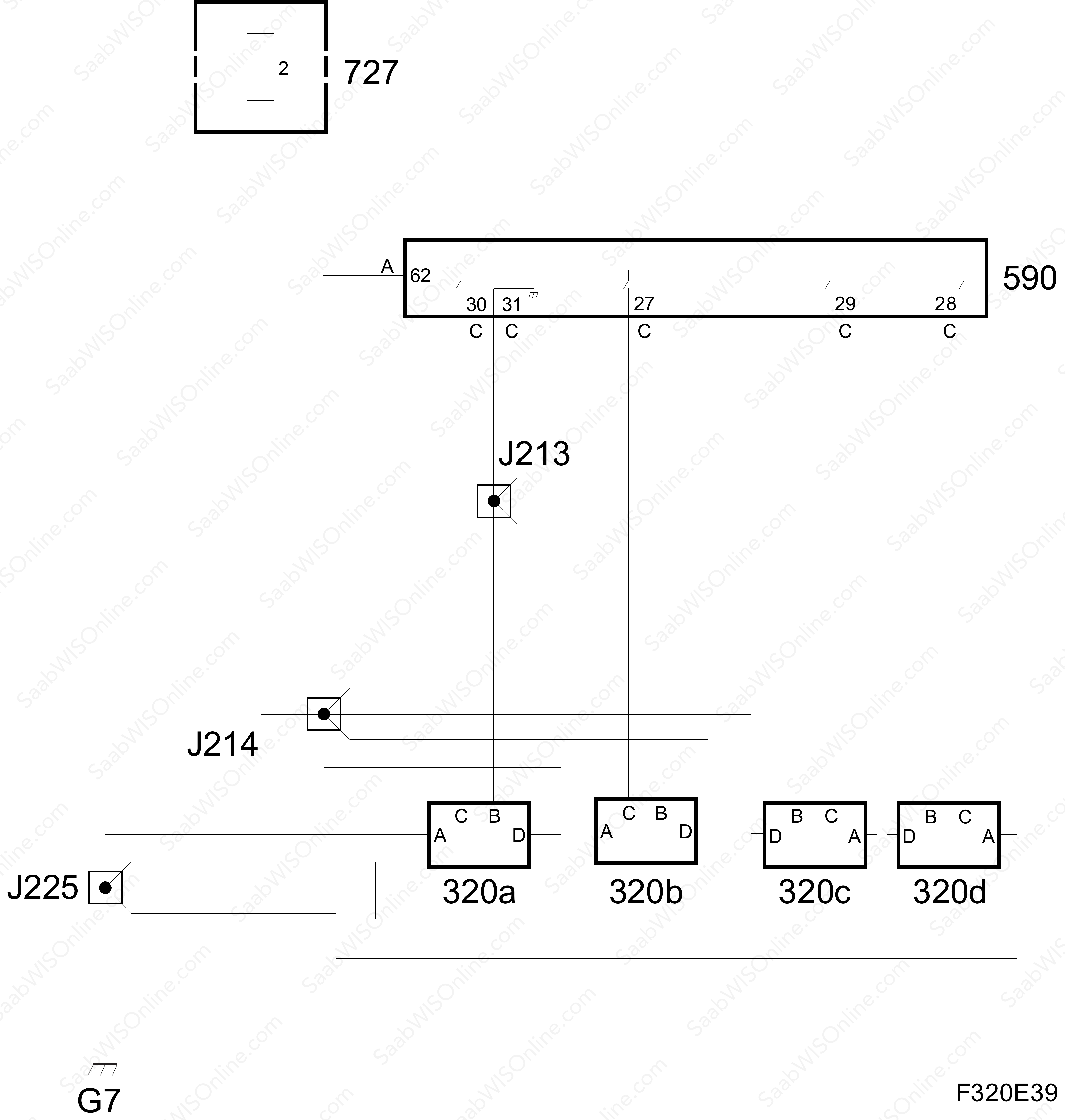
| D | Power supply, B+ | Connected to fuse 2 in the petrol engine management system fuse box (727) via crimp connection J214. |
| A | Ground | Connected to grounding point G7 via crimp connection J225. |
| B | Internal ground ECM | Connected to ECM, pin 31(C), via crimp connection J213. |
| C | Ignition trigger lead | Connected to ECM, pin 30(C). |
| Ignition system, cyl 2, 320b pin no | Signal type | Description |
| D | Power supply, B+ | Connected to fuse 2 in the petrol engine management system fuse box (727) via crimp connection J214. |
| A | Ground | Connected to grounding point G7 via crimp connection J225. |
| B | Internal ground ECM | Connected to ECM, pin 31(C), via crimp connection J213. |
| C | Ignition trigger lead | Connected to ECM, pin 27(C). |
| Ignition system, cyl 3, 320c pin no | Signal type | Description |
| D | Power supply, B+ | Connected to fuse 2 in the petrol engine management system fuse box (727) via crimp connection J214. |
| A | Ground | Connected to grounding point G7 via crimp connection J225. |
| B | Internal ground ECM | Connected to ECM, pin 31(C), via crimp connection J213. |
| C | Ignition trigger lead | Connected to ECM, pin 29(C). |
| Ignition system, cyl 4, 320d pin no | Signal type | Description |
| D | Power supply, B+ | Connected to fuse 2 in the petrol engine management system fuse box (727) via crimp connection J214. |
| A | Ground | Connected to grounding point G7 via crimp connection J225. |
| B | Internal ground ECM | Connected to ECM, pin 31(C), via crimp connection J213. |
| C | Ignition trigger lead | Connected to ECM, pin 28(C). |

| Connections |
ECM, pin 62(A), is connected to B+ at fuse 2 in the petrol engine management system fuse box (727) via crimp connection J214.
The ignition system is powered with B+ on the respective pins D via crimp connection J214 from fuse 2 in the petrol engine management system fuse box (727).
It is grounded through respective pin A to grounding point G7 via crimp connection J225
The ignition trigger leads from ECM are connected to respective pin C and the ECM ground for these is connected to ECM pin 31(C) via crimp connection J213.
| Ignition |
When the main relay in the petrol engine system fuse box (727) has operated, B+ is delivered to injector pins D. Once pin C on each ignition coil receives B+ from ECM, a power transistor integrated in the ignition coil will close the primary circuit.
The primary winding comprises relatively few turns of copper wire. A magnetic field now gradually forms in the ignition coil. When the spark is to fire, ECM applies B+ to pin C and high tension will now be induced across the secondary winding of the ignition coil.
The time during which ECM applies B+ to pin C to form the magnetic field in the ignition coils depends on battery voltage and engine speed. The voltage on the secondary side is much higher and it builds up until a spark jumps across the spark plug gap, which happens at approx 5-30 kV depending the conditions prevailing in the relevant cylinder. High pressure, which occurs when the engine is under load, requires a higher voltage than lighter running conditions.
The ignition coils can generate higher voltages, up to 40 kV.
| Charging time, general |
The charging time of the ignition coils depends on the system voltage and engine speed. The objective is to obtain a spark with the correct energy/high tension, irrespective of battery voltage and engine speed.
The charging time is in the region of 4 ms at 2000 rpm at normal system voltage.
| Principle, voltage dependent |
A lower battery voltage requires a longer charging time to obtain the same spark energy/high tension.
A higher battery voltage requires a shorter charging time, which avoids unnecessary ignition coil heating and reduces wear on the spark plug electrodes.
| Principle, engine speed dependent |
The charging time of the ignition coils is also engine speed dependent. This is to provide the correct energy/high tension to the spark. No more, which would stress the spark plug, and no less, which could cause misfiring.


