PRE-RELEASE
Turbocharger, system description, E39
| Turbocharger, system description, E39 |
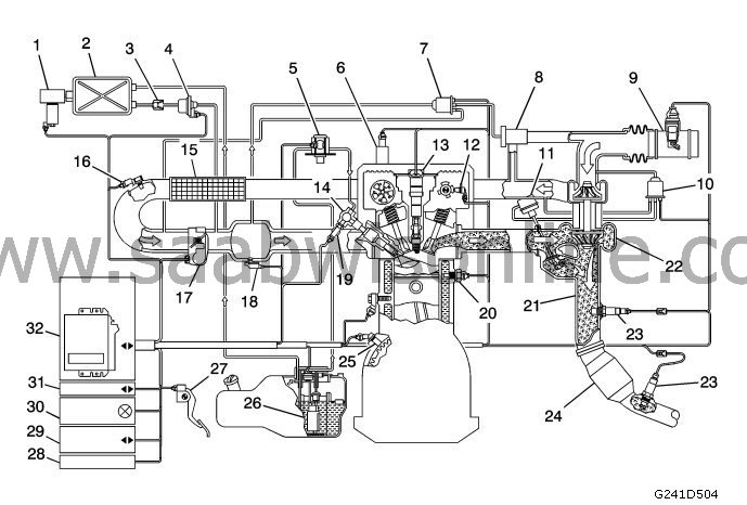
(1) Solenoid valve, EVAP shut-off (588 (fuel evaporation ventilation)
(2) EVAP reservoir
(3) Check valve
(4) Solenoid valve, EVAP canister purge (321)
(5) Fuel pump, high pressure (801)
(6) Solenoid valve, variable camshaft, intake (693)
(7) Solenoid valve, turbo bypass (605)
(8) Bypass valve
(9) Mass air flow sensor unit (686)
(10) Boost pressure control valve (179a)
(11) Diaphragm valve for turbocharger wastegate
(12) Position sensor, camshaft exhaust (555e)
(13) Ignition coil with integral power stage, cyl. 1-4 (320a-d)
(14) Injector cyl. 1-4 (206a-d)
(15) Charge air cooler
(16) Intake air sensor (688)
(17) Throttle body actuator unit (604)
(18) Manifold absolute pressure sensor (431)
(19) Fuel pressure sensor, fuel rail (653)
(20) Coolant temperature sensor (202)
(21) Exhaust pipe
(22) Turbocharger
(23) Preheated oxygen sensor, front and rear (592 and 593)
(24) Catalytic converter
(25) Crankshaft position sensor (345)
(26) Fuel pump unit (689)
(27) Accelerator pedal position sensor (379)
(28) Theft protection
(29) Diagnostic socket, 16-pin, CARB (445)
(30) CHECK ENGINE indicator lamp (MIL) (47o)
(31) GMLAN Serial data
(32) Control module, E39 (ECM) (590)
| Turbocharger, description and function |
A turbocharger is a compressor used to increase engine output by increasing the supply of oxygen to the engine, thereby making it possible to feed and burn more fuel.
The twin turbocharger from BorgWarner™ is mounted on the exhaust manifold and its lightweight turbine is driven by the unutilised energy in the exhaust flow. The turbine is connected to the turbocharger via a shaft mounted on the engine intake system. The turbocharger blades compress the intake air over atmospheric pressure, thereby increasing the density of the air being fed into the engine.
The turbocharger houses a wastegate, which is controlled by the engine control module (ECM) via a pulse-width modulated (PWM) solenoid, to regulate the pressure conditions of the turbocharger. An integrated turbocharger bypass valve, which is controlled by ECM via a solenoid, is used to counteract turbocharger pressure surges and damage from vibrations caused by the throttle valve closing quickly.
The bypass valve is opened with engine braking and closed throttle valve, which lets the air recirculate in the turbocharger and maintain turbocharger speed. During a command with fully open throttle valve, the bypass valve is closed to optimise turbo response.
The turbocharger is connected to the engine's oil system by a supply line and a return line. Mobil 1™ synthetic oil is used from the factory. Synthetic oil is required for its friction reducing qualities and its performance at high temperatures. There is a cooling system circuit in the turbocharger which uses engine coolant to further reduce the operating temperature.
| Turbocharger wastegate valve |
The wastegate valve opens and closes a duct that bypasses the turbine wheel. A coil spring works in the closing direction and the pressure at the membrane works in the opening direction.
ECM sends a PWM signal to the solenoid valve, which then allows pressure from the turbocharger through. When the pressure exceeds the spring force of the actuator, the rod begins to move and opens the wastegate valve to an equivalent degree. ECM changes the wastegate valve opening by varying the PWM signal that regulates turbine speed.
Under low loads, the wastegate valve is closed. All exhaust gases then pass through the turbine. Under high loads, the volume of exhaust gases is greater, which causes the turbine wheel to rotate more quickly. This creates a higher air flow to the engine.
When the amount of air becomes so great that the current air mass per combustion stroke cannot be controlled with the throttle valve alone, the turbocharger must also be regulated. This is done by opening the wastegate valve so that some of the exhaust gases pass through the wastegate. Subsequently, these exhaust gases do not help to drive the turbine and the speed of the turbine will be regulated so that the turbocharger air quantity is correct.
When certain DTCs are activated, ECM limits the amount of available boost pressure. Boost pressure limitation is achieved by ECM regulating the solenoid valve of the wastegate control element and keeps the pulse length at 0%. This means that ECM does not actively close the wastegate under high engine loads. At this point, the system is limited to mechanical boost pressure.
Mechanical boost pressure means that the wastegate still moves, but the movement is limited by the mechanical properties of the return spring inside the diaphragm valve, the pneumatic properties of the control element and the physical properties of the exhaust flow in the exhaust system.
The turbocharger wastegate diaphragm valve has a threaded road and nut which connect the valve diaphragm to the wastegate. This rod is adjusted to the BorgWarner™ factory specifications and cannot be adjusted.
The following diagram illustrates the turbocharger wastegate valve when closed and open:
Turbocharger wastegate closed
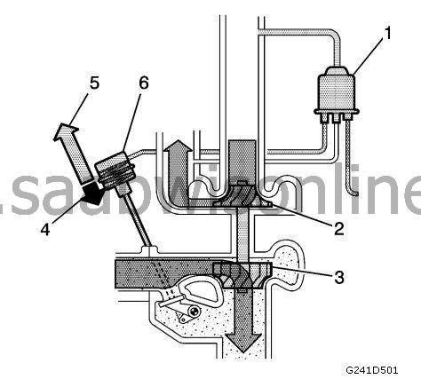
(1) Charge air solenoid valve (179a) (pulse length 100 percent)
(2) Compressor
(3) Turbine
(4) Exhaust pressure
(5) Spring force
(6) Diaphragm valve for turbocharger wastegate
Turbocharger wastegate open
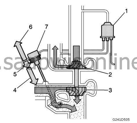
(1) Charge air solenoid valve (179a) (pulse length 0 percent)
(2) Compressor
(3) Turbine
(4) Control pressure
(5) Exhaust pressure
(6) Spring force
(7) Diaphragm valve for turbocharger wastegate
The wastegate is completely closed at idle. All exhaust energy passes through the turbine.
Under normal operation, when a fully open throttle valve is requested at lower speeds, the ECM will control the control valve solenoid valve with a pulse length of 100% in order to minimise any turbo lag. Under engine load at medium and high speeds, the ECM commands the solenoid with a pulse interval of 65-80%.
| Turbocharger bypass valve |
The turbocharger bypass valve prevents the turbocharger from exceeding the pump limit at low flow and high pressure. This occurs when the engine is run with a specific load and the throttle valve is closed quickly. In such cases, the flow is practically zero and pressure is extremely high.
This is not only harmful to the turbocharger, but also generates noise and reduces turbine speed. ECM sends a voltage signal to the solenoid valve, which regulates the open or closed position of the valve.
Accelerator pedal depressed
The bypass valve is closed. The force of the return spring integrated in the valve presses the valve cone against the seat in the turbo housing. The valve is closed off.Accelerator pedal released
To prevent pressure surges in the intake manifold and to relieve or release the turbo, ECM sends a voltage signal to the bypass valve, which then opens. The compressed air on the pressure side of the turbo is sent to the intake via the open valve.When the pressure drops, the turbine speed is kept relatively high and the turbocharger is prevented from exceeding the pump limit.
| Charge air cooler |
The turbocharger is supplied via an air-to-air charge air cooling system. The system sends fresh air through the heat exchanger to reduce the temperature of the hotter, compressed air taken into the induction system.
The intake air temperature can be reduced up to 100°C (180°F), which improves performance due to oxygen's higher density in cooled air, which facilitates optimal combustion.
The charge air cooler is connected to the turbocharger and throttle body with curved ducts, which require use of special fastening clamps with high tightening torque. To prevent all types of air leakage when performing air duct servicing, it is vital to follow the tightening torque specifications and positioning of the clamps.
