Control module, SCM (587), E39
|
|
Control module, SCM (587), E39
|
A 4-cylinder petrol engine (2.0 Biopower) and 6-speed automatic transmission (AF40-6) from the Saab 9-5 has been adapted for use in the Saab 9-3. Bus messages are structured slightly differently on the two vehicles and a converter is needed in order to fit the new ECM/TCM control modules.
The Signal Conversion Module (SCM) is fitted under the upper radiator crossmember and is connected to the P bus. It reads, converts and retransmits messages so that the control modules from both the 9-3 and 9-5 platforms can interpret the content. SCM has a number of other tasks to perform in order to handle the new engine and gearbox.
The SCM hardware is a T8 control module that has been provided with new software after a number of minor adjustments. The SCM can be contacted with the scan tool and it sets its own DTCs for the functions it is responsible for.
Control module, SCM (587), E39.
Fitted in engine bay, under upper radiator crossmember.
Location:
Control module, SCM (587), E39
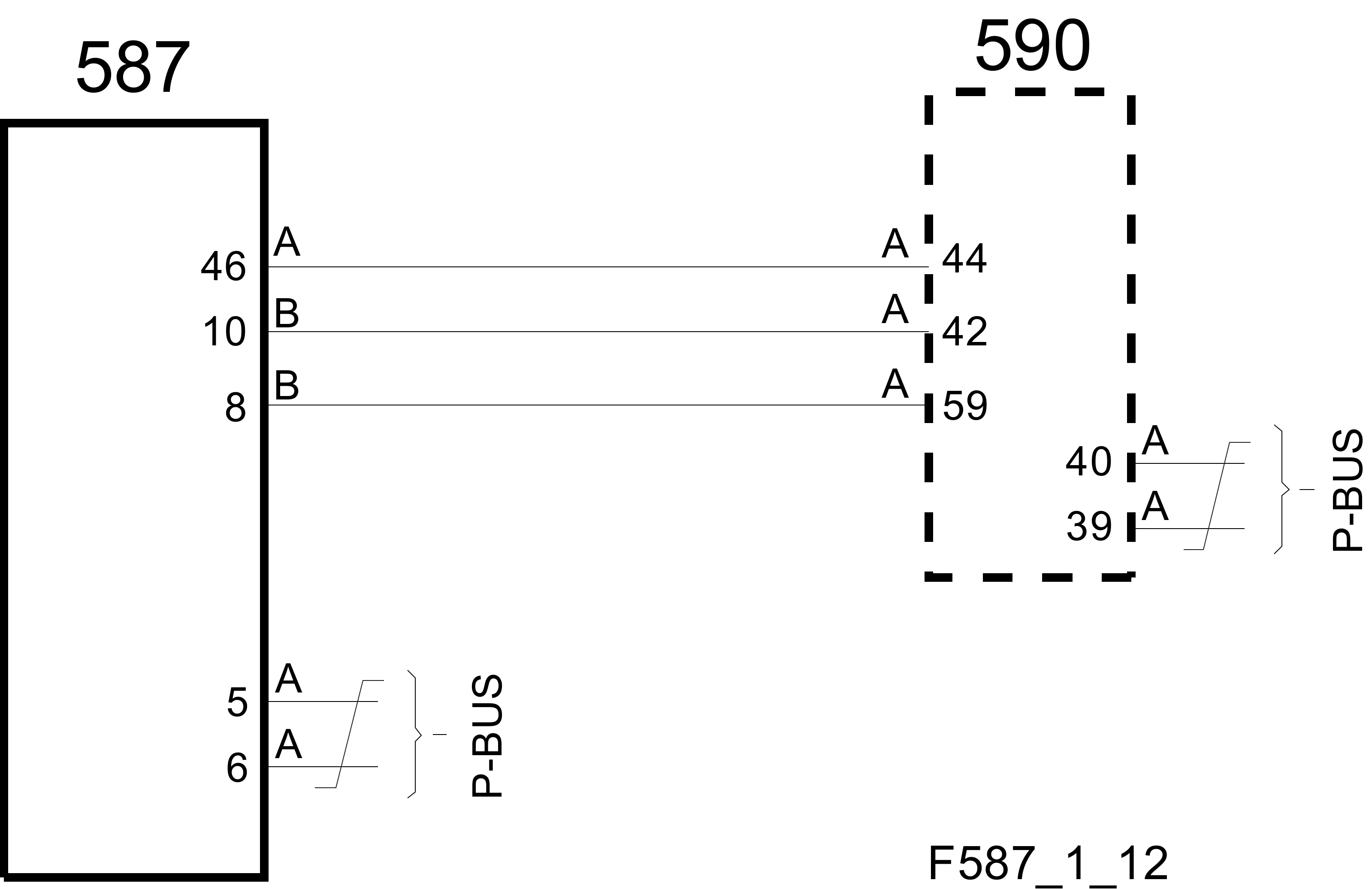
Connections on control module, SCM (587), E39 generation 1
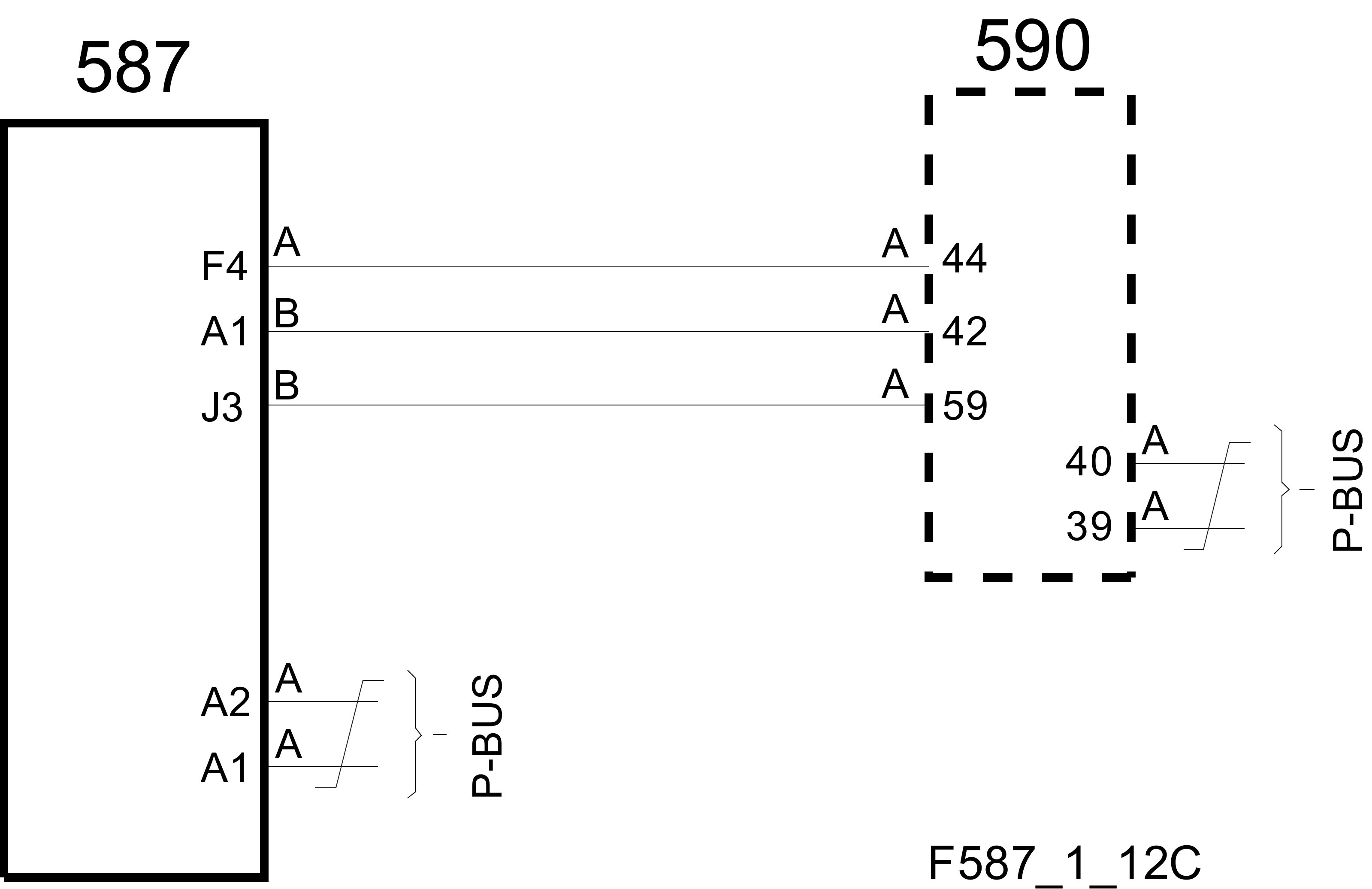
Connections on control module, SCM (587), E39 generation 2
Cruise Control
The software that controls the cruise control function differs on the 9-3 and 9-5. The buttons that are used to activate cruise control are also different. SCM will read data from the 9-3 control modules and not only convert them but also create new messages that agree with the revised cruise control function in the 9-5. Conversely, the SCM will provide the 9-3 control modules with the messages it requires.
Fan Control
The ECM from the 9-5 has 2 outputs that can be used for fan control. It has a driving stage that grounds the 2 wires when they are active. Three similar outputs are used on the 9-3 to generate 4 fan speeds. Together with the 2 outputs from the 9-5 control module, a total of 4 modes can be obtained 00, 01, 10 and 11, which is not sufficient for 4 speeds plus fan off. SCM reads the status from ECM for fan off and the first 3 speeds. A bus message from ECM is used for the highest speed. SCM grounds the 3 leads to the relay box for the radiator fans (706).
|
Voltage
|
Fan off
|
Stage 1
|
Stage 2
|
Stage 3
|
Stage 4
|
|
ECM → SCM Pin B8 (BJ3)
|
high
|
high
|
low
|
low
|
low
|
|
Pin B10 (BA1)
|
high
|
low
|
high
|
low
|
low
|
|
Bus signal
|
off
|
off
|
off
|
off
|
on
|
|
SCM → relay box pin A17 (AN2)
|
high
|
low
|
high
|
low
|
low
|
|
Pin A33 (AJ4)
|
high
|
high
|
low
|
low
|
low
|
|
Pin A61 (AF4)
|
high
|
high
|
high
|
high
|
low
|
Fuel Pressure Control
SCM is intended to control the fuel pressure from the petrol pump in the tank so that it always corresponds with the ECM bus request. The pump is driven by a driving stage, which in turn receives information on SCM from pin A51 (AC1). The output signal from SCM is a PWM at 128 Hz, where the pulse width controls the final stage pump current between 0 and 12 A. In order for SCM to activate the pump, it is necessary for ECM to apply B+ on SCM pin A46 (F4). SCM uses a 3-wire analogue pressure sensor mounted on the pipe between the tank and the engine in order to read off the current pressure. The sensor coupling looks like this:
|
•
|
5 V supply pin A41 (BE1)
|
|
•
|
Signal pin A7 (AD3)
The output stage of the pump is controlled so that the value of the pressure sensor corresponds to the pressure requested by ECM. The actual and desired values can be read using the scan tool.
|
Charge Regulation
The charge regulator is used to ensure the battery is always charged with an optimum voltage, mainly to decrease fuel consumption. The system enables a lower system voltage when the degree of battery charge is high. The alternator from the 9-5 platform does not have a regulator as such and is controlled via a PWM interface from ECM. The logic for the charge regulator is in BCM on the 9-5. The corresponding charge logic is now implemented in SCM. SCM retrieves input data for the function from BCM, which in turn receives data from the Intelligent Battery Sensor (IBS), which is mounted on the negative battery terminal. The following IBS data is used by SCM:
The equation for calculating the charge voltage results in a PWM value as a percentage that is sent on the bus by SCM. ECM will then lay out a 128 Hz PWM with this pulse ratio on the alternator's L terminal. The pulse ratio varies between 10-90 per cent, corresponding to charge voltage of 11.0-15.5V. The voltage varies relatively greatly with this system. Directly after cold starts in winter with a cold battery with 70 per cent charge degree or lower, the voltage can be set to 15.5V and when driving with a charge degree of over 90 per cent in the battery, the voltage can be set to 12.4V for long periods.
Data Conversion
SCM is connected to the P bus and converts bus data between the older 9-3 platform and ECM/TCM that comes from the newer 9-5 platform. The buses are not separated physically as the bus type is the same. The messages are numbered differently however. Some examples follow:
|
Message
|
9-3 Bus Frame Number:
|
9-5 Bus Frame Number:
|
|
Start request (from CIM 9-3)
|
$310
|
$1F1
|
|
TCS max torque (from ABS 9-3)
|
$140
|
$1C7
|
|
Current gear (from TCM 9-5)
|
$320
|
$1F5
|
|
Engine speed (from ECM 9-5)
|
$110
|
$0C9
|
The example above shows that the start request from CIM is read from message $310 and is put in $1F1 so that ECM can interpret it and activate the starter motor. The engine speed sent on the P bus by ECM is read from message $0C9 and is put in message $110 so that CIM can interpret it and send it on to the I bus so that MIU shows the engine speed on the tachometer.
Sport Mode
In the 9-3, this message means that the function is active or inactive. In the 9-5, it means that the button is depressed or not. SCM converts the signal so that ECM/TCM can interpret it correctly.
Shift Up logic
The Shift Up lamp in the MIU has previously been controlled by ECM. This task has now been taken over by SCM. In this way, the same logic found in T8 for this function can be retained. The lamp comes on in manual cars if a higher gear would result in lower fuel consumption.
Tip logic
On the 9-3, there is a wire between SLM and TCM for manual shifting of the automatic transmission. This signal goes via the bus for TCM on the 9-5. The wire is now therefore connected to SCM, which reads the voltage value from the resistive multiplex gear selector switch on pin B11 and sends information further on the bus.


