Wiring harness, engine A20NFT/LHU
|
|
Wiring harness, engine A20NFT/LHU
|
|
1.
|
Protect against paint damage and dirt over the wings.
|
|
2.
|
Remove the upper engine cover.
|
|
3.
|
Remove the battery cover.
|
|
4.
|
Undo the battery terminals and remove the battery.
|
|
6.
|
Undo the cable clip under the battery tray.
|
|
7.
|
Unplug the bonnet switch connector.
|
|
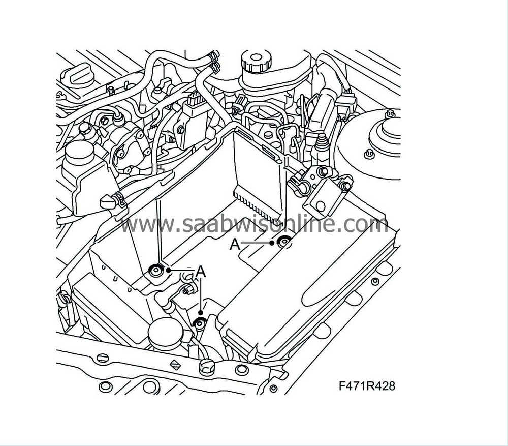
8.
|
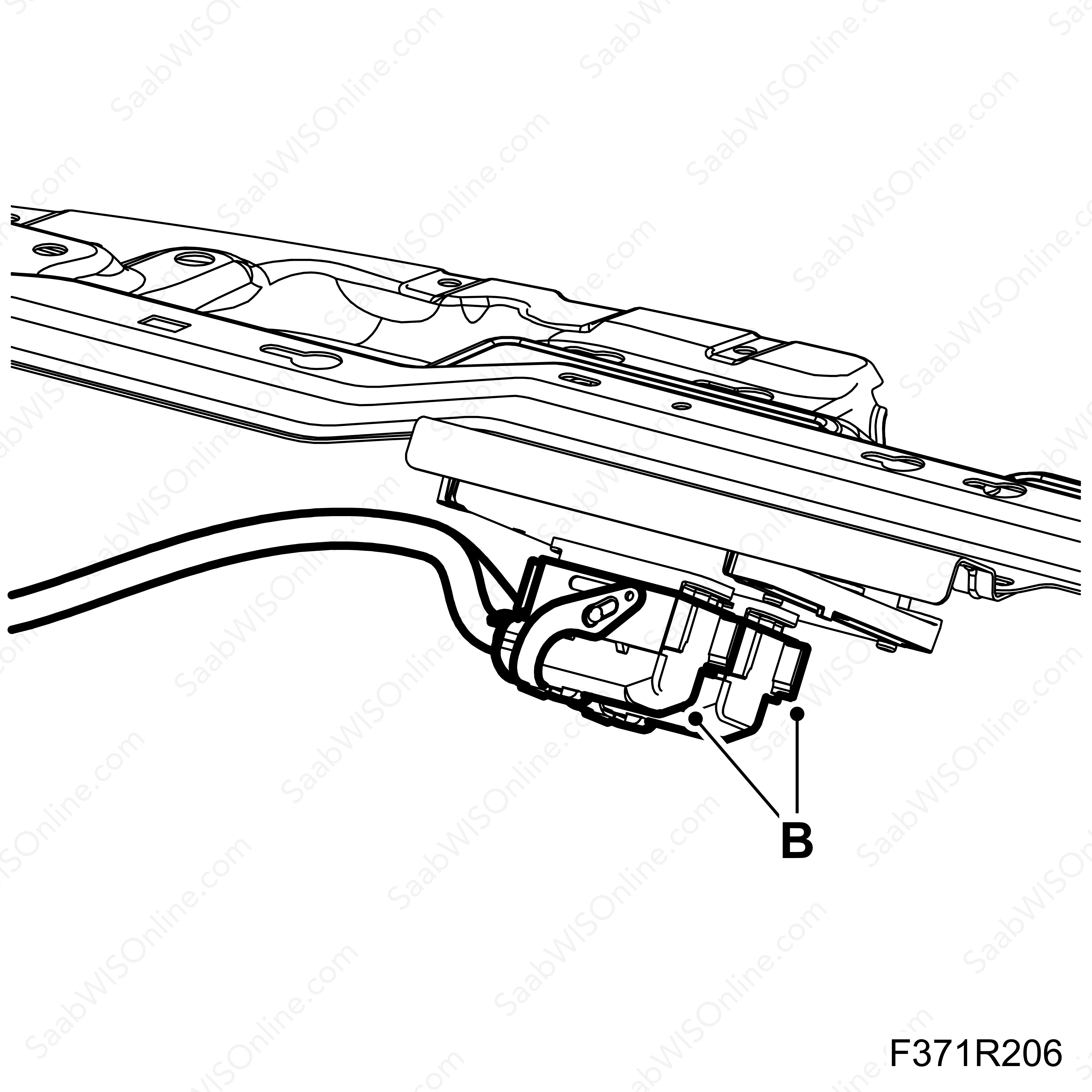
Remove the battery tray (A).
|
|
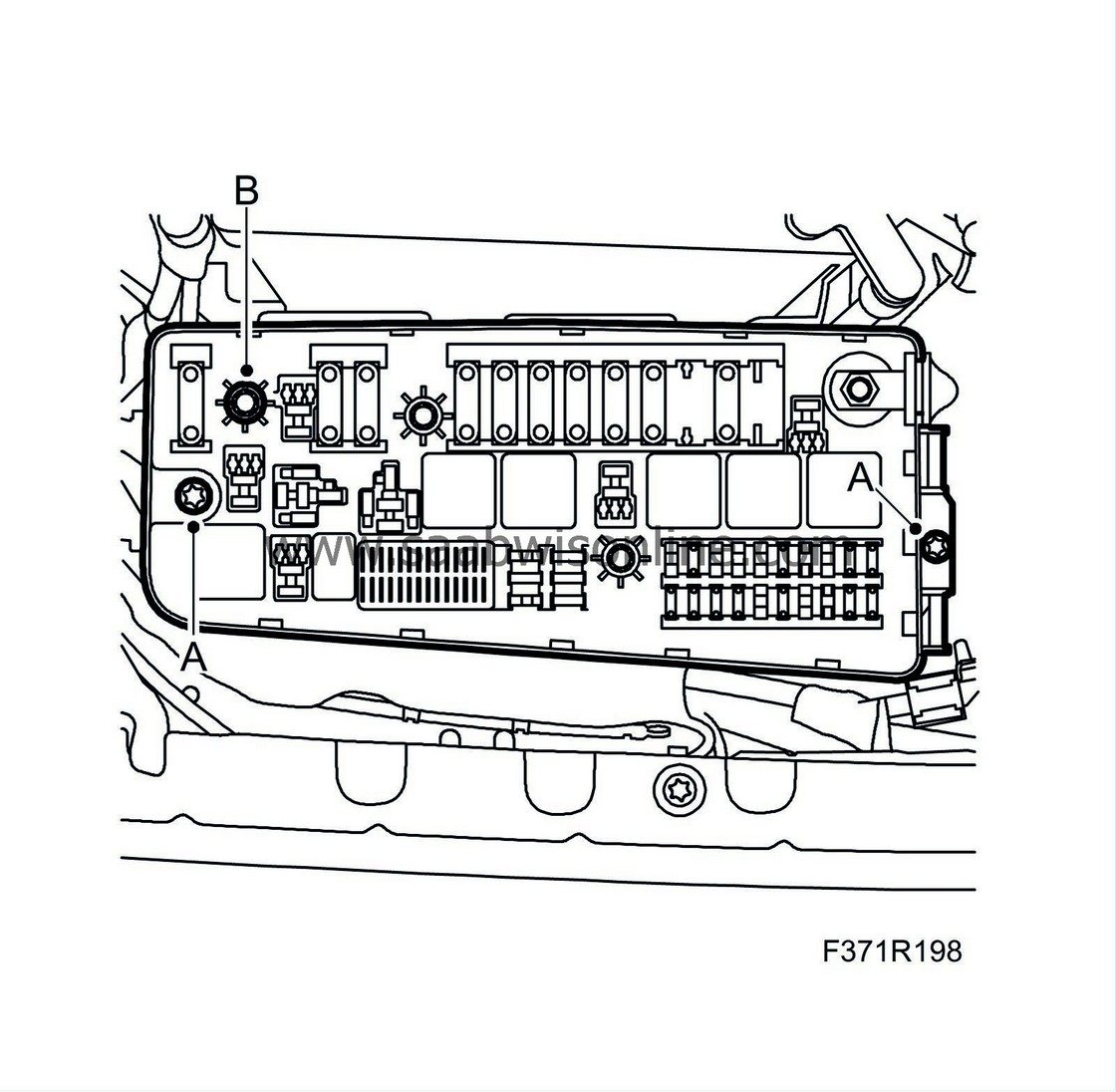
9.
|
Undo the top part of the fuse box (A) from the bottom (342).
|
|
10.
|
Remove the engine wiring harness from the fuse box (B).
|
|
11.
|
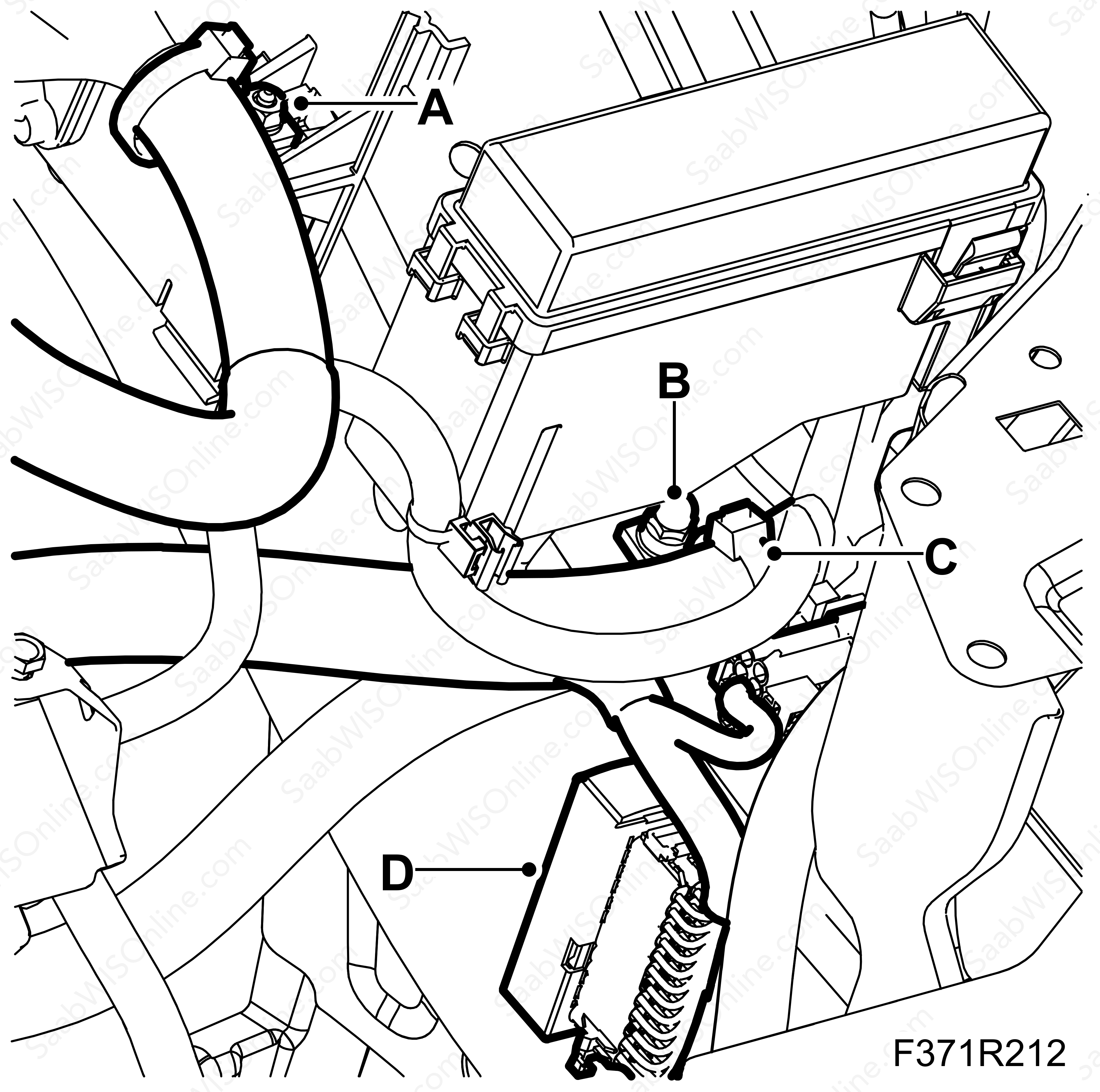
Remove clamps (A) and (B).
|
|
12.
|
Undo connector (D) (H24-2).
|
|
14.
|
Unplug connector (D) from the intake air sensor (688).
|
|
|
-
|
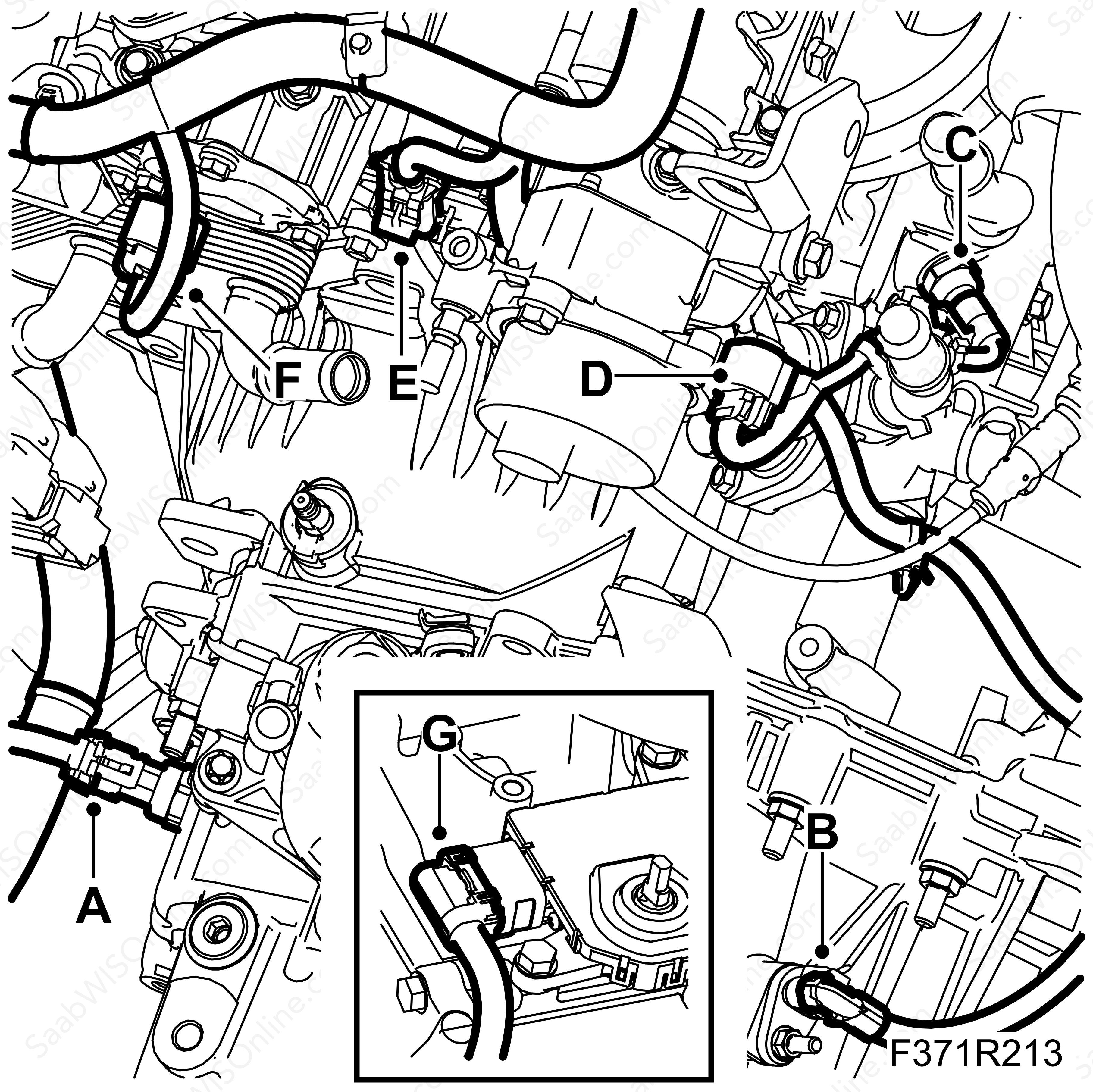
Unplug connector (A) from the reversing light switch (31).
|
|
|
-
|
Unplug the connector (B) gearbox output shaft speed sensor (533).
|
|
|
-
|
AF40 Automatic transmission
|
|
|
-
|
Unplug connector (G) from the TCM transmission control module (502A).
|
|
15.
|
Unplug connector (C) from the engine coolant temperature sensor (202).
|
|
16.
|
Unplug connector (D) from the exhaust camshaft position sensor (555E).
|
|
17.
|
Unplug connector (F) from the intake camshaft position sensor (555I).
|
|
18.
|
Unplug connector (E) from the front heated oxygen sensor (592).
|
|
19.
|
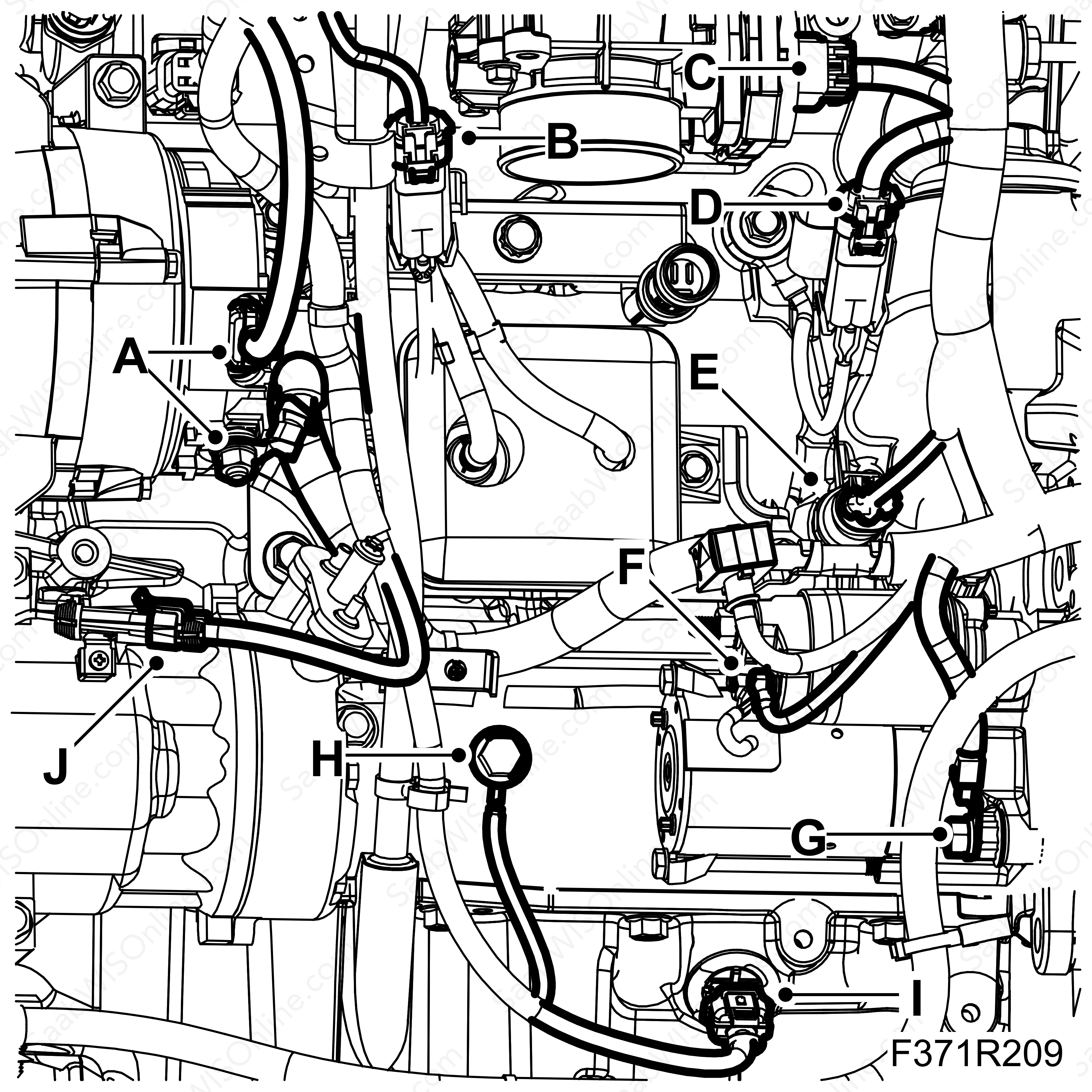
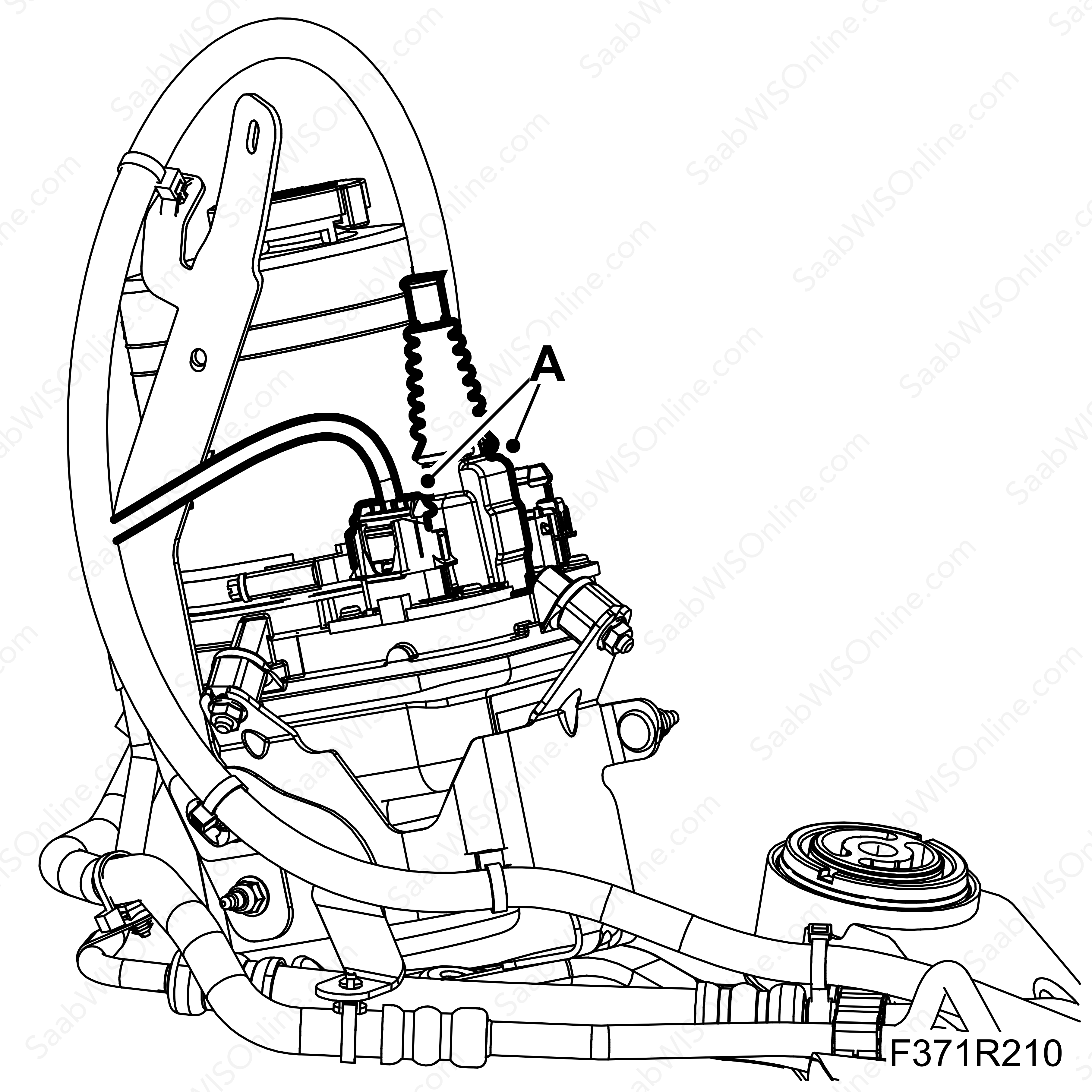
Unplug both electrical contacts (A) on the alternator (2).
|
|
20.
|
Unplug electrical connections (F) on the starter motor (4).
|
|
21.
|
Unplug the connectors from the knock sensor (B) and (D), (178a, 178b).
|
|
22.
|
Unplug connector (C) from the electronic throttle actuator (604).
|
|
23.
|
Unplug connector (E) engine oil pressure sensor(696).
|
|
24.
|
Unplug the ground cable connections (H) and (G) from the starter motor and engine block.
|
|
25.
|
Unplug connector (I) from the engine oil level switch (243).
|
|
26.
|
Unplug connector (J) from the A/C compressor (170).
|
|
27.
|
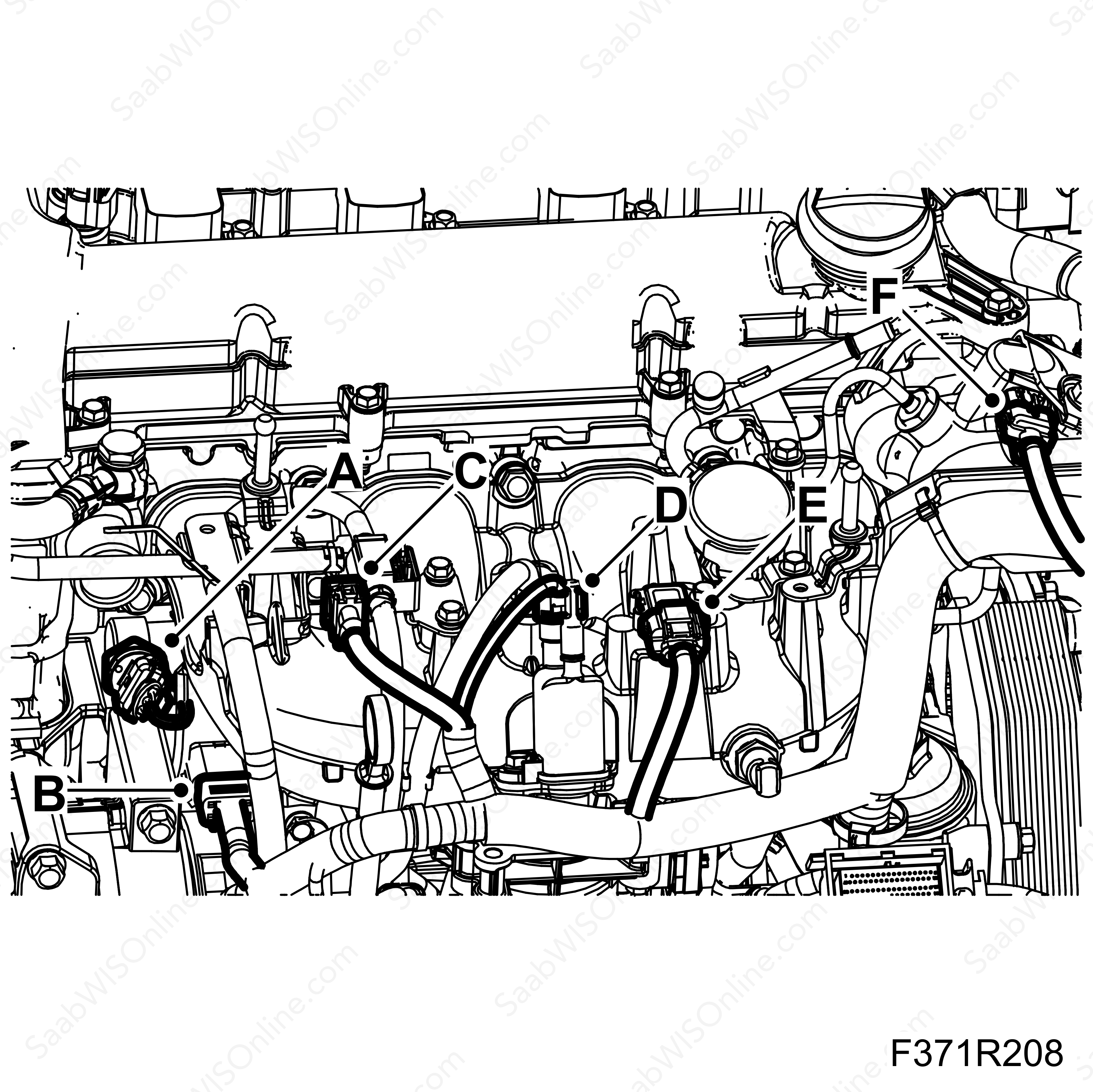
Unplug connector (A) from the fuel rail pressure sensor (653).
|
|
28.
|
Separate connector (B) nozzle wiring harness (H8-9).
|
|
29.
|
Unplug connector (C) from the turbo by-pass solenoid valve (605).
|
|
30.
|
Unplug connector (D) from the EVAP solenoid valve (321).
|
|
31.
|
Unplug connector (E) from the intake manifold temperature and pressure sensor (431).
|
|
32.
|
Unplug connector (F) from the high pressure fuel pump (801).
|
Important
|
|
Take care when plugging in the connector so as not to damage or press out the pins/sleeves in the connector. For further information regarding connectors, refer to
Connectors, handling and inspection
.
|
|
|
|
|
33.
|
Unplug connector (B) from the SCM control module (587).
|
|
34.
|
Detach the wiring harness from the clips on the end of the camshaft cover.
|
|
35.
|
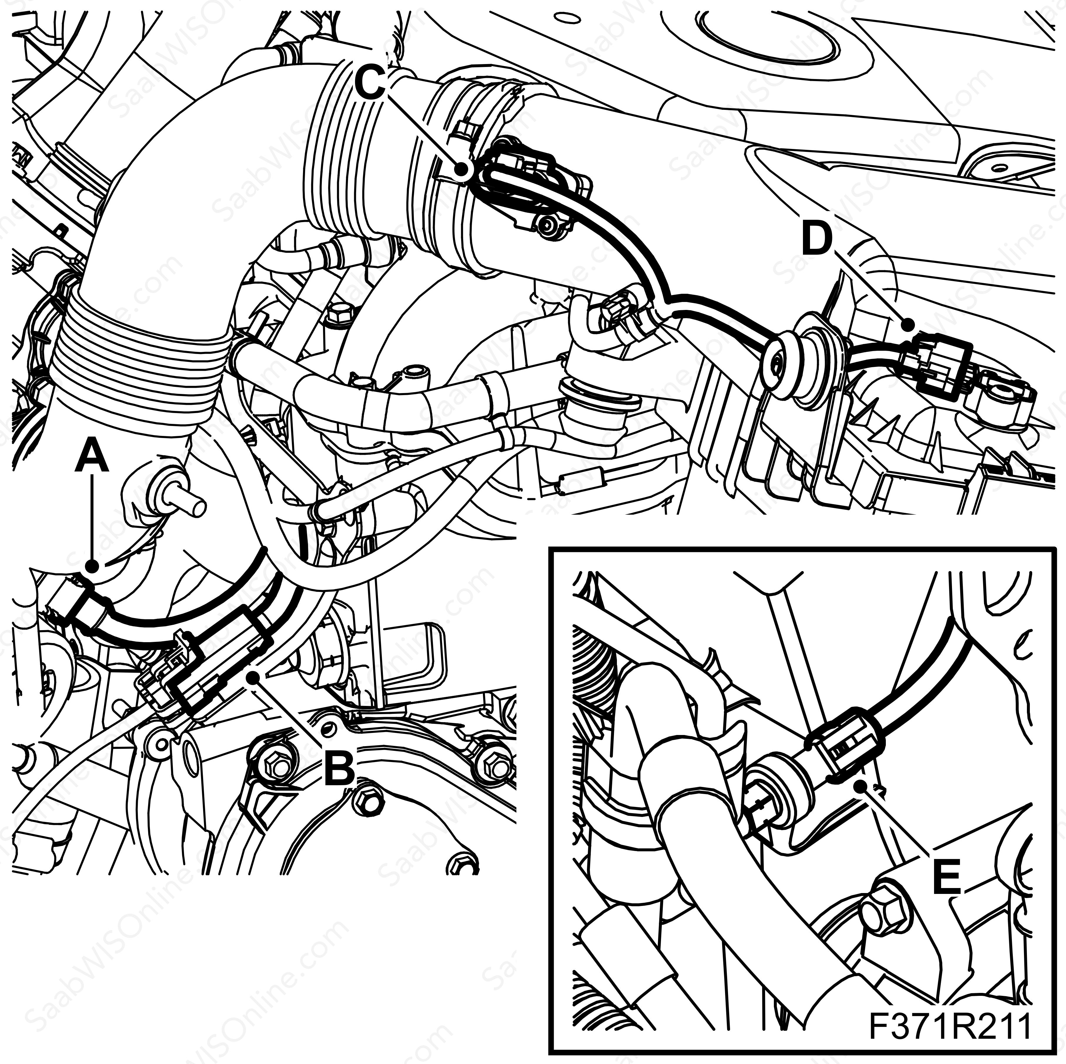
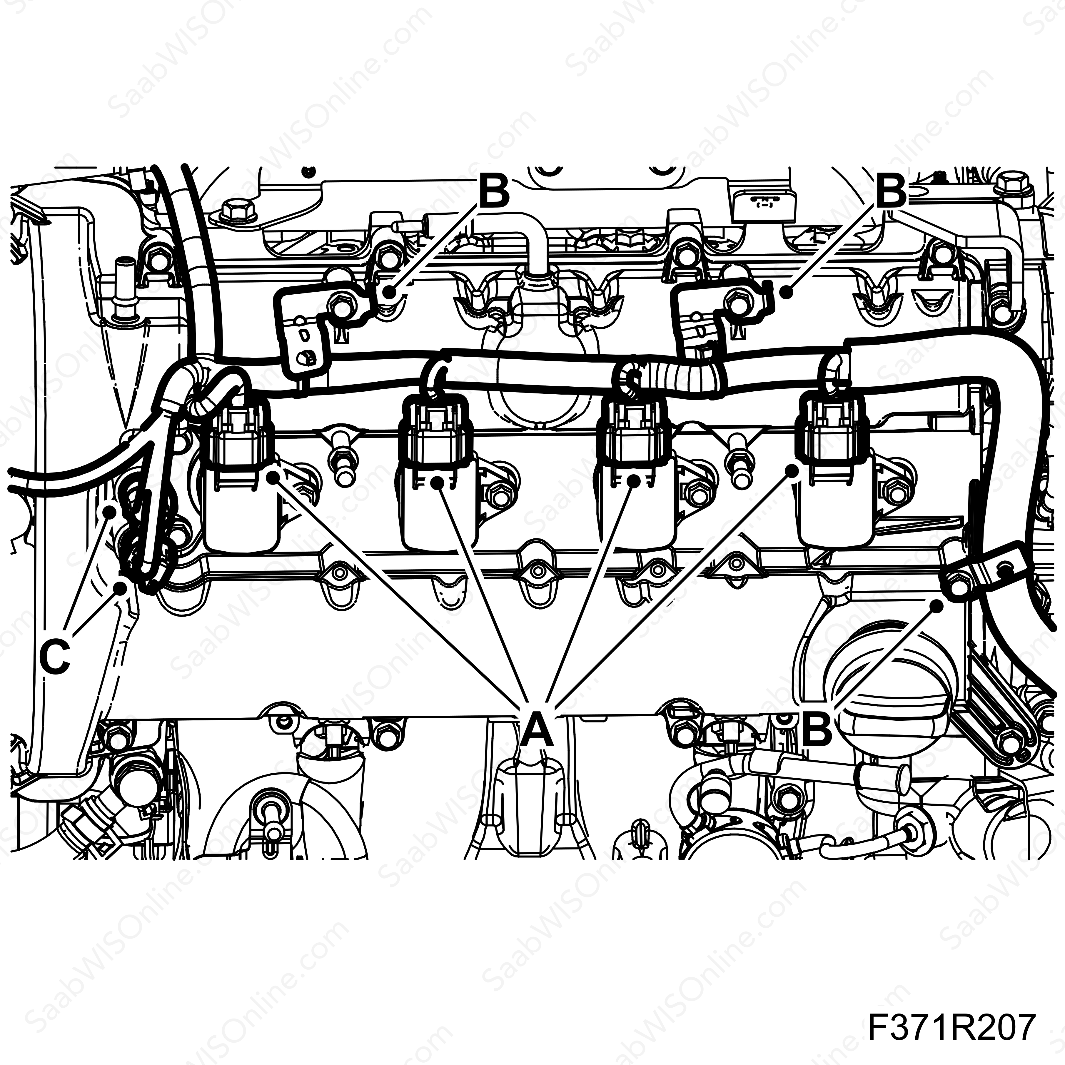
Unplug the connector from the wastegate solenoid valve (A) (179a).
|
|
36.
|
Unplug connector (B) from the heated oxygen sensor (593).
|
|
37.
|
Unplug connector (C) mass air flow sensor (686).
|
|
38.
|
Unplug connector (D) atmospheric pressure sensor (539).
|
|
39.
|
Unplug connector (E) from A/C pressure sensor(620).
|
|
40.
|
Unplug connector (A) from the ignition coils (320 a, b, c, d).
|
|
41.
|
Unscrew the wiring harness bracket (B), 3 x screws.
|
|
42.
|
Unplug connector (C) variable camshaft solenoid valve (693, 694).
|
|
44.
|
Unplug connector (A) power steering unit (745).
|
|
45.
|
Detach the wiring harness from clips and fixings.
|
|
46.
|
Lift up the wiring harness in the area between the radiator fan and the oil filter.
|
|
1.
|
Lower the wiring harness in the area between the radiator fan and the oil filter.
|
|
2.
|
Place the electrical connectors near the connecting points and fasten.
|
|
3.
|
Start by mounting the electrical harness connector to the fuse box (B) (342).
|
|
4.
|
Assemble the top and bottom of the fuse box (A).
|
|
5.
|
Fit clamps (A) and (B).
|
|
6.
|
Assemble connector (D) (H24-2).
|
|
7.
|
Plug in the connector (C).
|
|
8.
|
Plug in connector (D) intake air connector (688).
|
|
|
-
|
Plug in connector (A) to the reversing light switch (31).
|
|
|
-
|
Plug in the connector (B) gearbox output shaft speed sensor (533).
|
|
|
-
|
AF40 Automatic transmission
|
|
|
-
|
Plug in connector (G) to the TCM transmission control module (502A).
|
|
10.
|
Plug in connector (C) engine coolant temperature sensor (202).
|
|
11.
|
Plug in connector (D) to the exhaust camshaft position sensor (555E).
|
|
12.
|
Plug in connector (F) to the intake camshaft position sensor (555I).
|
|
13.
|
Plug in connector (E) to the front heated oxygen sensor (592).
|
|
14.
|
Plug in both electrical contacts (A) on the alternator (2).
|
|
15.
|
Plug in electrical connections (F) on the starter motor (4).
|
|
16.
|
Plug in connector (B) and (D) knock sensor (178a, 178b).
|
|
17.
|
Plug in connector (C) electronic throttle actuator (604).
|
|
18.
|
Plug in connector (E) engine oil pressure sensor(696).
|
|
19.
|
Plug in the ground cable connections (H) and (G) to the starter motor and engine block.
|
|
20.
|
Plug in connector (I) engine oil level switch (243).
|
|
21.
|
Plug in connector (J) A/C compressor (170).
|
|
22.
|
Plug in connector (A) fuel rail pressure sensor (653).
|
|
23.
|
Assemble connector (B) nozzle wiring harness (H8-9).
|
|
24.
|
Plug in connector (C) turbo by-pass solenoid valve (605).
|
|
25.
|
Plug in connector (D) EVAP solenoid valve (321).
|
|
26.
|
Plug in connector (E) intake manifold temperature and pressure sensor (431).
|
|
27.
|
Plug in connector (F) high pressure fuel pump (801).
|
Important
|
|
Take care when plugging in the connector so as not to damage or press out the pins/sleeves in the connector. For further information regarding connectors, refer to
Connectors, handling and inspection
.
|
|
|
|
|
28.
|
Plug in connector (B) SCM control module (587).
|
|
29.
|
Plug in the wiring harness to the end of the camshaft cover.
|
|
30.
|
Plug in connector (A) to the wastegate solenoid valve (179a).
|
|
31.
|
Plug in connector (B) heated oxygen sensor (593).
|
|
32.
|
Plug in connector (C) mass air flow sensor (686).
|
|
33.
|
Plug in connector (D) atmospheric pressure sensor (539).
|
|
34.
|
Plug in connector (E) A/C pressure sensor (620).
|
|
35.
|
Plug in connector (A) ignition coils (320 a, b, c, d).
|
|
36.
|
Screw on the wiring harness bracket (B), 3 x screws.
|
|
37.
|
Plug in connector (C) variable camshaft solenoid valve (693, 694)
|
|
38.
|
Plug in connector (A) power steering unit (745)
|
|
39.
|
Attach wiring harness to clips and fixings
|
|
41.
|
Fit the bottom of the battery cover.
|
|
43.
|
Fit the battery and batter cover.
|
|
44.
|
Fit the upper engine cover and remove the wing covers.
|


