Propeller Shaft Phasing Inspection
|
|
Propeller Shaft Phasing Inspection
|
Special Tools
J-23498-A
Driveshaft Inclinometer , or equivalent
|
Note
|
|
This inspection procedure is intended to inspect propeller shaft systems with 2 or 3 U-joints only.
|
Correct phasing of a propeller shaft refers to the relative alignment of the U-joint yoke flanges to each other to provide proper cancellation of the U-joints. The yokes should be directly aligned to within the range specified in this procedure.
|
1.
|
Raise and support the vehicle. On vehicles with solid axles, ensure that the drive axle is supported at ride height - vehicle body supported by suspension components. Ensure the wheels are free to rotate. Refer to
Lifting and Jacking the Vehicle
.
|
|
2.
|
Place the transmission into NEUTRAL.
|
|
3.
|
Clean any corrosion or foreign material from the U-joint bearing caps.
|
|
4.
|
Remove any of the U-joint bearing cap snap rings that may interfere with the correct placement of the
J-23498-A
Driveshaft Inclinometer , or equivalent .
|
|
5.
|
Inspect the prop shaft for proper phasing.
|
|
|
5.1.
|
Rotate the prop shaft or shafts to align the shaft yoke flanges vertically.
|
|
|
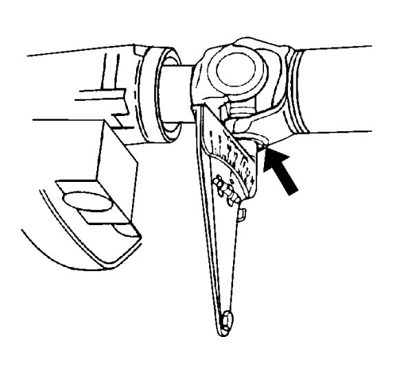
5.2.
|
Install
J-23498-A
drive shaft inclinometer or corresponding on the bearing cap on the front u-joint, the yoke for which is now aligned vertically.
J-23498-A
inclinometer for drive shaft or equivalent should be aligned perpendicular to the propeller shaft.
|
|
|
5.3.
|
Set the indicator line on the
J-23498-A
Driveshaft Inclinometer , or equivalent to 15, the horizontal reference.
|
|
|
5.4.
|
Rotate the propeller shaft slightly to center the bubble to the indicator. The U-joint is now vertical.
|
|
|
5.5.
|
Without disturbing the setting on the
J-23498-A
Driveshaft Inclinometer, or equivalent, remove the
J-23498-A
Driveshaft Inclinometer, or equivalent from the rear U-joint bearing cap .
|
|
|
5.6.
|
Install the
J-23498-A
Driveshaft Inclinometer , or equivalent to the lower U-joint bearing cap of the front U-joint of the same shaft.
|
|
|
5.7.
|
Observe and record the reading of the front U-joint with the
J-23498-A
Driveshaft Inclinometer , or equivalent still set to 15, the horizontal reference.
|
|
6.
|
For prop systems with 3 U-joints, rotate the shafts 1/4 turn and repeat steps 5.1-5.7 for the other prop shaft.
|
|
7.
|
If the difference between the front and rear U-joints of a welded yoke propeller shaft is 3 degrees or less, the propeller shaft is properly phased.
|
|
8.
|
If the difference between the front and rear U-joints of a welded-yoke propeller shaft is greater than 3 degrees, the propeller shaft is either constructed improperly, or damaged from twisting. Refer to
Propeller Shaft Phasing Correction
.
|
|
9.
|
If the difference between the welded yoke and slip yoke of a propeller shaft is 1.5 degrees or less, the prop shaft is properly phased.
|
|
10.
|
If the difference between the welded yoke and slip yoke of a propeller shaft is greater than 1.5 degrees, the propeller shaft is either constructed improperly, or damaged from twisting. Refer to
Propeller Shaft Phasing Correction
.
|
