PRE-RELEASE
Electronic Vibration Analyzer (EVA) Description and Operation
| Electronic Vibration Analyzer (EVA) Description and Operation |
Special Tools
| • |
EL-38792-25
Inductive Pickup Timing Light
|
|
| • |
EL-38792-A
Electronic Vibration Analyzer 2 (EVA 2)
|
|
For equivalent regional tools, refer to Special Tools and Equipment .
EL-38792-A Electronic Vibration Analyzer 2 (EVA 2) is a 12 V handheld instrument, similar to a diagnostic tool, which receives signals from a connected vibration sensor or accelerometer and shows the predominant input frequencies (up to three) on the LCD display. The frequencies in the problem vibration are found using EL-38792-A Electronic Vibration Analyzer 2 (EVA 2) and the Diagnostic tables for vibration analysis. The frequency(ies) obtained, when applied to the Vibration Analysis Diagnostic Tables, are used as a primary input to help determine the source of the vibration concern.
| EVA Vibration Sensor |
The EL-38792-A Electronic Vibration Analyzer 2 (EVA 2) vibration sensor incorporates a 6.1 m (20 ft) cord, that allows the sensor to be placed on virtually any component of the vehicle where a vibration concern is felt.
The EL-38792-A Electronic Vibration Analyzer 2 (EVA 2) contains 2 sensor input ports which can be activated individually to allow for 2 individual vibration sensor inputs. The vibration sensors can then be placed in 2 different locations in the vehicle and their individual inputs can be read without having to stop a test, move the sensor and resume the test. The use of 2 vibration sensors can help in more quickly finding and recording an accurate frequency of the vibration concern, and in more quickly making comparisons between 2 different areas of a single component, or a vehicle system, during the diagnostic process.
EVA Vibration Sensor Placement
The correct location of the vibration sensor (accelerometer) for EL-38792-A Electronic Vibration Analyzer 2 (EVA 2) is critical so you can be sure that the correct vibration readings are obtained with EL-38792-A Electronic Vibration Analyzer 2 (EVA 2). The vibration sensor must be placed on the vehicle component which has been found to react most strongly to the vibration. If no component has been identified, install the sensor to the steering column as a starting point.EVA Vibration Sensor-to-Component Attachment
The vibration sensor of the EL-38792-A Electronic Vibration Analyzer 2 (EVA 2) is designed to pickup disturbances which primarily occur in the vertical plane, since most vibrations are felt in that same up-and-down direction. The EL-38792-A Electronic Vibration Analyzer 2 (EVA 2) vibration sensor is therefore directional sensitive and must be attached to vehicle components such that the side of the sensor marked UP is always facing upright and the sensor body is as close to horizontal as possible. The sensor must be installed in the exact same position each time tests are repeated or comparisons are made to other vehicles.| Note | ||
|
The EL-38792-A Electronic Vibration Analyzer 2 (EVA 2) vibration sensor must be attached to vehicle components in the manner indicated in order to achieve accurate frequency readings of the vibration disturbance. |
The EL-38792-A Electronic Vibration Analyzer 2 (EVA 2) vibration sensor can be attached to vehicle components in various ways. For non-ferrous surfaces, such as the shroud of a steering column, the sensor can be attached using putty, or hook and loop fasteners. For ferrous surfaces, the sensor can be attached using a magnet supplied with the sensor.
| EVA Software Cartridge |
EL-38792-A Electronic vibration analyzer 2 (EVA 2) uses a software card, EL-38792-60, that supplies EL-38792-A Electronic vibration analyzer 2 (EVA 2) with various information. EL-38792-60 supplies EL-38792-A Electronic vibration analyzer 2 (EVA 2) with an extra function that can be selected and used to assist when diagnosing vibration problems.
| Note | ||
|
The Auto-Mode function of the EL-38792-A Electronic Vibration Analyzer 2 (EVA 2) cartridge, EL-38792-60, is designed to be used in SUPPORT of the Vibration Analysis Diagnostic Tables ONLY. |
This support function is available via the Auto Mode function in EL-38792-A Electronic Vibration Analyzer 2 (EVA 2). When the function is selected, EL-38792-A Electronic Vibration Analyzer 2 (EVA 2) reminds the user to choose which of the 2 vehicle systems (vehicle speed or engine speed) is the SUSPECTED source of the vibration problem. Using the inputted vehicle data parameters along with the most dominate vibration frequency obtained, it will identify a SUSPECTED source of the vibration concern, such as first-order tire and wheel. This can be a useful feature when used in conjunction with the Vibration Analysis Diagnostic Tables, to confirm results obtained through the diagnostic process.
| EVA Smart Strobe Function |
EL-38792-A Electronic vibration analyzer 2 (EVA 2) can be used to identify some rotating components/systems that show imbalance IF the component's rpm is the vibration problem's dominating frequency. EL-38792-A Electronic vibration analyzer 2 (EVA 2) is equipped with a sensor line for stroboscope that can be used for a stroboscope light with inductive sensor, EL-38792-25 Stroboscope light with inductive sensor or similar included in EL-38792-25-KIT or available separately. Using the Smart Strobe function enables the user to input the vibration frequency to which the strobe will flash. Select the suspected rotating component, e.g., belt pulley, and adjust the stroboscope's frequency to fit the dominating vibration frequency at the engine rpm that was noted during diagnostics. Then run the engine at this rpm, the marking on the object will be stationary if this object is imbalanced.
| EVA Strobe Balancing Function |
EL-38792-A Electronic vibration analyzer 2 (EVA 2) can be used to identify the light point on a propeller shaft IF the propeller shaft's rpm is the vibration problem's dominating frequency. EL-38792-A Electronic vibration analyzer 2 (EVA 2) is equipped with a sensor line for stroboscope that can be used for a stroboscope light with inductive sensor, EL-38792-25 Stroboscope light with inductive sensor or equivalent included in EL-38792-25-KIT or available separately and in combination with the vibration sensor for EL-38792-A Electronic vibration analyzer 2 (EVA 2) to identify the light point on a propeller shaft and help to determine when the propeller shaft's balance has been achieved.
| Averaging/Non-Averaging Modes |
The EVA provides 2 modes of displaying the most dominate frequencies which the EVA vibration sensor (accelerometer) detects; averaging and non-averaging (instantaneous).
The averaging mode uses multiple vibration samples taken over a period of time and then displays the most dominant frequencies which have been averaged-out. Using the averaging mode minimizes the distractions caused by a sudden vibration frequency being displayed that is not related to the concern vibration, such as from pot holes or from uneven road surfaces.
The non-averaging (instantaneous) mode is more sensitive to vibration disturbances than the averaging mode. Using the non-averaging mode will generate instantaneous frequency displays which are not averaged across multiple samples over a period of time. The specific vibration frequencies that occur at a specific moment during diagnostic testing will be displayed at that moment. The non-averaging (instantaneous) mode is useful when measuring a vibration disturbance that exists for only a short period of time or during acceleration/deceleration testing.
When operating the EVA in the averaging mode along with the Auto Mode, "A" will be displayed along the top of the screen to the left of the vibration sensor input port being used. When operating the EVA in the averaging mode and the Manual Mode, "AVG" will be displayed along the top center of the screen.
When operating the EVA in the non-averaging (instantaneous) mode along with the Auto Mode, "I" will be displayed along the top of the screen to the left of the vibration sensor input port being used. When operating the EVA in the non-averaging (instantaneous) mode and the Manual Mode, the top center of the screen will be blank.
| EVA Display |
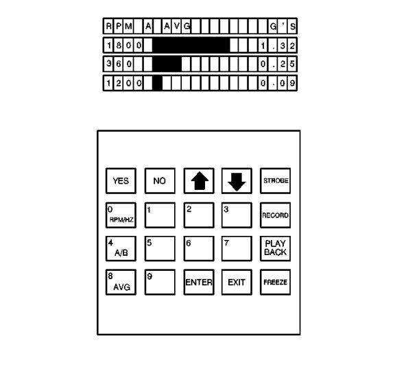
The frequency readings are displayed along the left side of the screen, followed to the right by either a bar graph or the suspected source of the vibration - depending upon the mode selected. The amplitude reading for each frequency along the right side of the screen. The top row of the screen indicates the units of measure being displayed for the frequencies along the left side and for the amplitudes along the right side. The top row also indicates the vibration sensor input port which was selected on the keypad (A or B) and which mode was selected: averaging or non-averaging (instantaneous).
The frequency can be shown either in revolutions per minute (RPM) or in revolutions per second; Hertz (Hz). The display position (RPM or Hz) selected is shown on the left side of the screen, above the frequency values.
When the AUTO MODE function is not in use, a bar graph is displayed next to each frequency to provide a quick visual indication of the relative amplitude strength.
When the AUTO MODE function is being used, the suspected source of the vibration is displayed next to each frequency to provide support to the diagnostic process.
The actual amplitude strength of each frequency is displayed at the right side of the screen and shown in G's-of-acceleration force.
