PRE-RELEASE
Engine Support Fixture (Centering Adapter)
| Engine Support Fixture (Centering Adapter) |
Special Tools
| • |
CH-904
Base Frame
|
|
| • |
CH-49289
Centering Adapter
|
|
| • |
CH-49289-1
Frame
|
|
| • |
CH-49289-2
Safety
|
|
| • |
CH-49289-3
Safety
|
|
| • |
CH-49289-4
Support Right
|
|
| • |
CH-49289-5
Support Left
|
|
| • |
CH-49289-6
Centering Pin
|
|
| • |
CH-49289-7
Arm Right
|
|
| • |
CH-49289-8
Rod Right
|
|
| • |
CH-49289-9
Arm Left
|
|
| • |
CH-49289-10
Rod Left
|
|
| • |
CH-49289-11
Adapter
|
|
| • |
CH-49289-12
Adapter
|
|
| • |
CH-49289-13
Adapter
|
|
| • |
CH-49289-14
Support
|
|
| • |
CH-49290
Mounting Engine/Gearbox
|
|
For equivalent regional tools, refer to Special Tools .
| Installation Procedure |
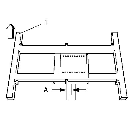
| 1. |
Install the
CH-904
base frame (1) to the hydraulic lift. The distance (A) has to be
40 mm (1.6 in)
.
|
|
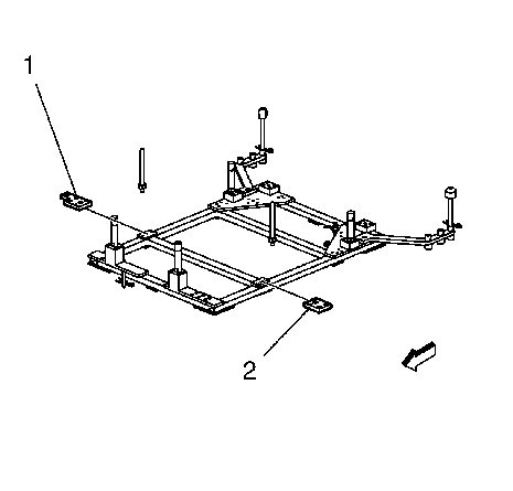
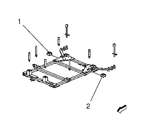
| 2. |
Install the
CH-49289-2
safety (2) and
CH-49289-3
safety (3) into the
CH-49289
centering adapter (1).

|
|
| 3. |
Install the
CH-49289
centering adapter to the
CH-904
base frame.
|
|
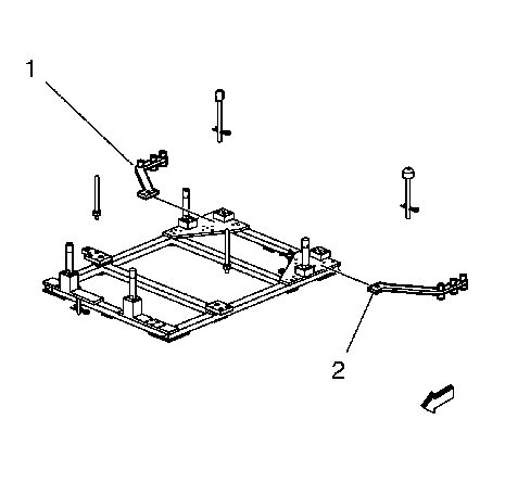
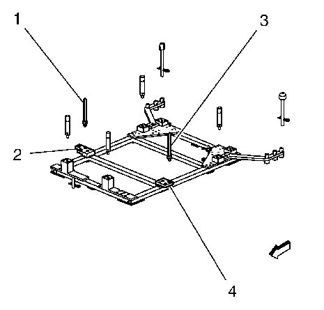
| 4. |
Install the
CH-49289-4
support right (1) to position "01".
|
|
| 5. |
Install the
CH-49289-5
support left (2) to position "02".
|
|
| 6. |
Install the
CH-49289-7
arm right (1) to position "04".
|
|
| 7. |
Install the
CH-49289-9
arm left (2) to position "06".
|
|
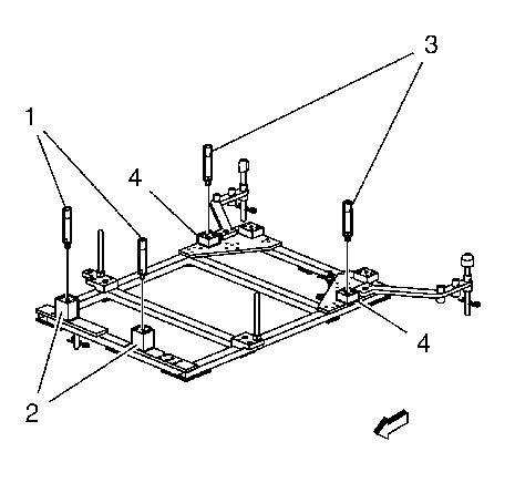
| 8. |
Install the
CH-49289-11
adapter (1) to position "08".
|
|
| 9. |
Install the
CH-49289-11
adapter (2) to position "09".
|
|
| 10. |
Install the
CH-49289-12
adapter (1) to position "15".
|
|
| 11. |
Install the
CH-49289-12
adapter (2) to position "18".
|
|
| 12. |
Install the
CH-49289-13
adapter (1) to position "19".

|
|
| 13. |
Install the
CH-49289-13
adapter (2) to position "22".
|
|
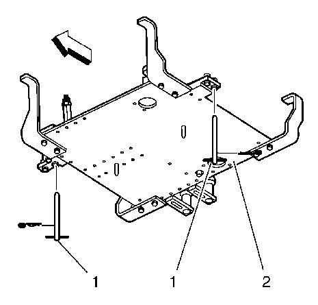
| 14. |
Install the
CH-49289-6 (1)
centering pin into
CH-49289-4
support right (2) to position "B".
|
|
| 15. |
Install the
CH-49289-6
centering pin (3) into CH-49289-5 (4) to position "E".
|
|
| 16. |
Install the CH-49289-8 rod right (1) into CH-49289-7 arm right (2) to position "H". 
|
|||||||
| 17. |
Install the
CH-49289-10
rod left (3) into
CH-49289-9
arm left (4) to position "M".
|
|
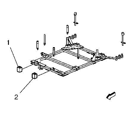
| 18. |
Install both
CH-49289-14
support (1) into both
CH-49289-11
adapter (2).
|
|
| 19. |
Install both
CH-49289-14
support (3) into both
CH-49289-12
adapter (4).
|
|
| 20. |
Raise and support the vehicle. Refer to
Lifting and Jacking the Vehicle
.
|
|
| 21. |
Installation in conjunction with
CH-49290
mounting engine: Remove both
CH-49290-6
pin (1) from the
CH-49290
mounting engine/gearbox (2).
|
|
| 22. |
Raise the hydraulic lift with CH-49289 centering adapter (2) to support the front suspension frame (1). 
|
|||||||
| 23. |
Install the
CH-49289
centering adapter parallel to the front suspension frame.
|
|
| Removal Procedure |
| 1. |
Remove the
CH-49289
centering adapter (2) from the front suspension frame (1).
|
|
| 2. |
Lower the hydraulic lift with
CH-49289
centering adapter.
|
|
| 3. |
Remove the
CH-49289
centering adapter from the
CH-904
base frame.
|
|
