PRE-RELEASE
Evaporative Emission Control System Description
| Evaporative Emission Control System Description |
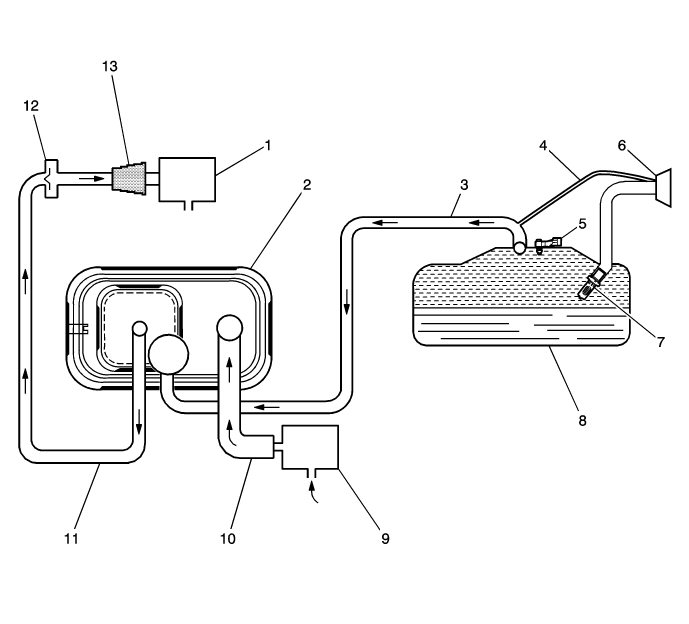
(1) Evaporative Emissions (EVAP) Purge Solenoid Valve
(2) EVAP Canister
(3) EVAP Vapor Tube
(4) Vapor Recirculation Tube
(5) Fuel Tank Pressure Sensor
(6) Fuel Filler Cap
(7) Fuel Fill Pipe Inlet Check Valve
(8) Fuel Tank
(9) EVAP Canister Vent Solenoid Valve
(10) Vent hose
(11) EVAP Purge Tube
(12) Check valve vent hose, turbocharged applications only
(13) EVAP Canister Purge Tube Connector
| EVAP System Operation |
The evaporative emission (EVAP) control system limits fuel vapors from escaping into the atmosphere. Fuel tank vapors are vented due to the pressure in the tank via the EVAP's vapor pipe to the EVAP reservoir. Carbon in the reservoir absorbs and stores the fuel vapors. Excess pressure is vented through the vent hose and EVAP canister vent solenoid valve to the atmosphere. The EVAP canister stores the fuel vapors until the engine is able to use them. At the appropriate time the engine control module (ECM) commands the EVAP reservoir's drain valve to ON, so that engine vacuum is opened to the EVAP reservoir. When the normally open solenoid valve on the evaporative emission canister is OFF fresh air is sucked in through the vent valve and vent hose to the evaporative emission canister. Fresh air is drawn through the canister, pulling fuel vapors from the carbon. The air/fuel vapor mixture continues through the EVAP purge tube and EVAP purge solenoid valve into the intake manifold to be consumed during normal combustion. The control module uses several tests to determine if the EVAP system is leaking or restricted.
| Purge Solenoid Valve Leak Test |
If the evaporative emission (EVAP) purge solenoid valve does not seal properly fuel vapors could enter the engine at an undesired time causing driveability concerns. The ECM tests for this by commanding the EVAP purge solenoid valve OFF and the canister vent solenoid valve ON, which seals the system. With the engine running the ECM then monitors the fuel tank pressure sensor for an increase in vacuum the ECM will log a fault if a vacuum develops in the tank under these test conditions.
| Large Leak Test |
This diagnosis forms a vacuum relationship in the EVAP-system. When activation criteria have been fulfilled the control module requests the normally open vent valve on the evaporative emission canister to close and the vent valve open, which creates a vacuum in the EVAP system. The ECM then monitors the voltage from the fuel tank's pressure sensor to confirm that the system can reach a pre-determined vacuum level within a given time period. If the vacuum level cannot be reached it indicates that there is a major leak in the EVAP-system or a restriction in the venting channel. ECM registers a fault if it detects a worse vacuum level than expected during these conditions.
| Canister Vent Restriction Test |
If the evaporative emission (EVAP) vent system is restricted, fuel vapors will not be properly purged from the EVAP canister. The control module tests this by commanding the EVAP purge solenoid valve ON while commanding the EVAP canister vent solenoid valve OFF, and then monitors the fuel tank pressure sensor for an increase in vacuum. If the vacuum increases more than the expected amount, in a set amount of time, a fault will be logged by the ECM.
| Small Leak Test |
The engine off natural vacuum diagnostic is the smaller leakage detection for the bleed system (EVAP). The engine off natural vacuum diagnostic monitors the EVAP system pressure with the ignition OFF. Because of this, it may be normal for the control module to remain active for up to 40 minutes after the ignition is turned OFF. This is important to remember when performing a parasitic draw test on vehicles equipped with engine off natural vacuum.
When the vehicle is driven, the temperature rises in the tank due to heat transfer from the exhaust system. After the vehicle is parked, the temperature in the tank continues to rise for a period of time, then starts to drop. The engine off natural vacuum diagnostic relies on this temperature change, and the corresponding pressure change in a sealed system, to determine if an EVAP system leak is present.
The engine off natural vacuum diagnostic is designed to detect leaks as small as 0.51 mm (0.020 in).
| EVAP System Components |
The evaporative emission (EVAP) system consists of the following components:
