Radio/Audio System Description and Operation
|
|
Radio/Audio System Description and Operation
|
The entertainment system on this vehicle may have several different configurations available to it. To determine the specific configuration of the vehicle, please see the Service Parts ID Label, and refer to
RPO Code List
.
The entertainment system on this vehicle is configured with either a base or an uplevel system. The base and uplevel systems each contain a radio, antenna, speakers, and on some systems an audio amplifier. The uplevel system differs from the base system by providing the customer with enhanced audio system features. Some of those features may include the radio data system (RDS), an audio amplifier, programmable equalizer, and digital satellite radio (U2K).
Each item in the list below represents topics covered in detail below.
|
•
|
Radio Circuit Operation
|
|
•
|
Radio/HVAC Communications
|
|
•
|
Digital Radio Receiver (If equipped)
|
|
•
|
Audio Amplifier (If equipped)
|
|
•
|
Radio Data System (RDS) (If equipped)
|
|
•
|
Steering Wheel Controls (If equipped)
|
|
•
|
Auxiliary Audio Input Jack (If equipped)
|
|
•
|
Multimedia Player Interface Module (If equipped)
|
|
•
|
Noise Compensation (If equipped)
|
|
•
|
Speed Controlled Volume (SCV) (If equipped)
|
Radio Power
The radio does not use a discrete ignition feed circuit for power moding. The power mode master provides the system power mode to the radio via serial data messages. The power mode master determines the system power mode by processing power mode information from ignition switch inputs. Serial data power modes supported by the radio are OFF, ACCESSORY, RUN, and CRANK REQUEST.
Radio Grounds
The vehicle harness provides a ground for the radio circuits. The radio may also be case grounded.
Radio Data Link Communication
The radio communicates with other modules via serial data.
Radio Audio Outputs
Each of the audio output channel circuits (+) and (-), at the radio have a DC bias voltage that is approximately one half of battery voltage. The audio being played on the system is produced by a varying AC voltage that is centered around the DC bias voltage on the same circuit. The AC voltage is what causes the speaker cone to move and produce sound. The frequency (Hz) of the AC voltage signal is directly related to the frequency of the input (audio source playing) to the audio system. Both the DC bias voltage and the AC voltage signals are needed for the audio system to properly produce sound.
Remote Enable Output
The remote enable circuit is a discrete 12 V signal supplied to infotainment system components when the radio is producing audio, needs the front display on, needs video entertainment system components on, or needs to produce chimes. This signal is used to control the power state of the components. There is no output on radio to the remote enable circuit when the vehicle is in the CRANK power mode. This is to minimize current consumption from the attached modules and also to avoid audio pops during crank events.
Radio/HVAC Communications
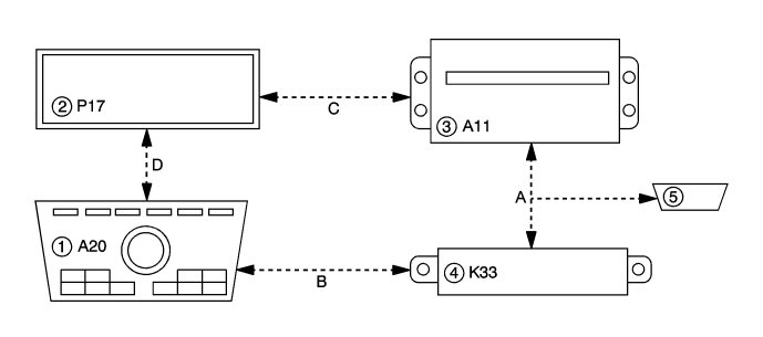
(1) Radio/HVAC Controls
(2) Info Display Module
(3) Radio
(4) HVAC Control Module
(5) Data Link Connector
(a) GMLAN
(b) Local Interconnect Network-HVAC
(c) CAN graphical interface
(d) Local Interconnect Network-Radio
The radio/HVAC controls is a separate component from the radio. The radio/HVAC controls contain the radio control knobs and buttons for all audio functions.
The radio/HVAC controls operate radio functions through serial data messages. The radio/HVAC controls communicate to the info display module through LIN serial data. The info display module communicates to radio through CGI serial data.
When equipped with the optional navigation radio, the radio/HVAC controls communicate directly to the navigation radio, and the display communicates information through the signal circuits to the navigation radio.
When the operator rotates a radio control knob to change radio stations or increase the volume a message is sent to the radio over serial data. After receiving the message the radio will make the adjustment. Messages communicated between the radio and the radio/HVAC controls and info display include the following:
|
•
|
Button presses/knob rotations
|
|
•
|
Info display module dimming
|
|
•
|
Radio/HVAC controls back-lighting
|
|
•
|
Graphics and text information
|
HVAC data for controls and status indicators is communicated between the radio/HVAC controls and the HVAC control module with a separate LIN serial data circuit. HVAC status screen information from the HVAC control module is transmitted to the radio on the GMLAN serial data circuit. The radio then displays the desired screen information on the info display using the video data circuits.
Multi-Band Antenna
The multi-band antenna is located on the roof of the vehicle. This type of antenna may be used with the AM/FM radio, but is primarily for OnStar® cellular and GPS signals and the XM™ Satellite Radio Service System, if the vehicle has these features. Keep this antenna clear of snow and ice build up for clear reception. If the vehicle has a sunroof, the performance of the system may be affected if the sunroof is open. Loading items onto the roof of the vehicle can interfere with the performance of the system, ensure the multi-band antenna is not obstructed.
Active Antenna
The active antenna system uses two integral antennas applied as appliqués to the rear glass. Each antenna is part of the rear window and looks similar to the defogger grid. One antenna receives AM signals while the other antenna receives FM signals. Any damage to the antenna requires replacing the glass.
The radio antenna module is enabled when the radio is turned on. The radio provides battery voltage to the antenna module using the center conductor of the antenna coaxial cable. This DC voltage does not affect the incoming radio signal. When a 12 V signal is seen by the module on the center conductor of the antenna coax, both AM and FM signals are amplified.
Radio Signal
The radio signal is sent from a broadcast station and is then received by an antenna. The strength of the signal received depends on the following:
|
•
|
The power output (wattage) of the broadcasting station
|
|
•
|
The location of the vehicle (or receiver) relative to the broadcast tower.
|
|
•
|
Obstacles between the tower and the receiver
|
|
•
|
What band (AM or FM) the station is broadcasting
|
|
•
|
Type of antenna and the ground plane
|
AM Reception
The AM band has a lower frequency range than the FM band. These longer wavelengths:
|
•
|
Follow the curvature of the earth
|
|
•
|
May reflect off the ionosphere (skip)
|
The AM frequencies have longer range due to the ground wave. The ground wave follows the curvature of the earth and is effected by its conductivity. Greater conductivity equates to less signal loss thus transmission over water is better than over land. The AM band has a range of 80-320 km (50-200 miles).
FM Reception
The shorter wavelengths of the higher frequency FM band:
|
•
|
Are absorbed by the ground
|
|
•
|
Penetrate the ionosphere
|
Broadcasts in the FM band are limited to line of sight reception which is typically 40 km (25 miles). Even when out of a direct line of sight, the signal may be reflected into areas that would be in a shadow otherwise. Factors which affect the line of sight include:
|
•
|
Height of the broadcast antenna
|
|
•
|
Height of the receiving antenna
|
|
•
|
Terrain and buildings in the broadcast path
|
|
Digital Radio Receiver (If equipped)
|
The XM satellite radio is integrated into the radio. XM satellite radio provides digital radio reception. The XM signal is broadcast from two satellites and, where necessary, terrestrial repeaters. The high power satellites allow the antenna to receive the XM signal even when foliage and other partial obstructions block the antennas view of the satellite. Terrestrial repeaters are used in dense urban areas. These repeaters will receive the satellite signal and re-broadcast them at much higher power levels in order to ensure reception in areas with densely packed tall buildings. A service fee is required in order to receive the XM service.
Speakers turn electrical energy into mechanical energy to move air, using a permanent magnet and an electromagnet. The electromagnet is energized when the radio or amplifier (if equipped) delivers current to the voice coil on the speaker. The voice coil will form a north and south pole that will cause the voice coil and the speaker cone to move in relation to the permanent magnet. The current delivered to the speaker is rapidly changing alternating current (A/C). This causes the speaker cone to move in two directions producing sound.
|
Audio Amplifier (If equipped)
|
Amplifier Interface
A fused battery voltage circuit provides the main amplifier power. A switched 12-volt output from the radio is used to control the power - state of the amplifier. To respond quickly to audio input and control signals, the amplifier is ON in all vehicle power modes except OFF and CRANK Request. The internal amplifier bridges are fully powered and unmuted when the amplifier receives the switched 12-volt input.
Amplifier Operation
The purpose of the amplifier is to increase the power of a voltage or current signal. The output signal of an amplifier may consist of the same frequencies as the input signal or it may consist of only a portion of the frequencies as in the case of a subwoofer or midrange speaker. The radio creates a low level stereo audio output signal, which is sent at the user-defined volume level to the audio amplifier. The audio amplifier amplifies the signal and sends it to the appropriate speakers. Each of the audio output channel circuits (+) and (-), from the amplifier have a DC bias voltage that is approximately one half of battery voltage. The audio being played on the system is produced by a varying AC voltage that is centered around the DC bias voltage on the same circuit. The AC voltage is what causes the speaker cone to move and produce sound. The frequency (Hz) of the AC voltage signal is directly related to the frequency of the input (audio source playing) to the audio system. Both the DC bias voltage and the AC voltage signals are needed for the audio system to properly produce sound.
|
Radio Data System (RDS) (If equipped)
|
The radio may be equipped with the Radio Data System (RDS). Ahe RDS feature is available only on FM stations that broadcast RDS information. This system relies upon receiving specific information from these stations and only works when the information is available. While the radio is tuned to an FM-RDS station, the station name or call letters display.
RDS data is carried in what is known as a "subcarrier". A subcarrier is a frequency that the FM broadcaster is authorized to use to send data that is not audible in the main audio program.
|
•
|
RDS functions will only work with FM broadcast stations that are broadcasting RDS data.
|
|
•
|
Not all FM Broadcast stations broadcast RDS data or offer all of the RDS services.
|
|
•
|
The information displayed is dependent upon the information broadcast by the particular station. The information may vary greatly between stations.
|
|
•
|
RDS functions may not work properly when reception is weak, reception is of poor quality, or RDS is not implemented properly by the FM Broadcaster.
|
|
•
|
In some cases, a radio station broadcasting incorrect information may cause the RDS features of the radio to appear to work improperly.
|
With RDS, the radio can do the following:
|
•
|
Seek to stations broadcasting the selected type of programming
|
|
•
|
Receive announcements concerning local and national emergencies
|
|
•
|
Display messages from radio stations
|
|
•
|
Recieve alert warnings of local or national emergencies. When an alert announcement comes on the current radio station, ALERT! displays. You will hear the announcement, even if the volume is low or a CD is playing. If a CD is playing, play stops during the announcement. Alert announcements cannot be turned off. ALERT! is not affected by tests of the emergency broadcast system. This feature is not supported by all RDS stations.
|
RDS may display text information such as:
|
•
|
The name of the station.
|
|
•
|
General information such as artist and song title, call in phone numbers, etc.
|
The radio theft deterrent system is intended to disable or limit radio functionality if incorrect vehicle information is received by the radio. The radio disables functionality if the VIN information received by the radio does not match the VIN information that has been learned by the radio. The radio receives this information via serial data. A possible cause of incorrect VIN info could be the radio was originally installed in another vehicle.
The radio has the following theft operating modes as part of the theft deterrent system:
|
•
|
Normal Mode: The radio has learned a correct VIN sequence and the VIN information received via serial data matches the learned VIN sequence. In this mode the radio has full functionality.
|
|
•
|
No VIN Mode: The radio has not received or learned a correct VIN sequence. In this mode the radio has limited functionality.
|
|
•
|
Theft Detected Mode: The radio has learned a correct VIN sequence and the VIN information received via serial data does not match the learned VIN sequence. This function can disable the radio or limit its functionality. The radio display will indicate that theft protection is active.
|
When OnStar is activated, a serial data message is sent to the radio that activates a software program. When the software begins its process, the fade goes to the front, Bass and Treble are set to the mid range, the outputs are mono, and the audio source is OnStar. OnStar takes priority over any other audio source. All of these actions are preset values stored in the radio.
For additional OnStar information, refer to
OnStar Description and Operation
.
|
Steering Wheel Controls (If equipped)
|
Some audio functions are available using the steering wheel controls. The steering wheel controls duplicate the function of the primary controls available on the radio.
For additional information on steering wheel controls, refer to
Steering Wheel Controls Description and Operation
.
|
Auxiliary Audio Input Jack (If equipped)
|
The infotainment system may have a 3.5mm (1/8 in.) auxiliary audio input jack located in the center console. The auxiliary audio input jack may interface directly with the radio, or be connected to the infotainment system via a Multimedia Player Interface Module. When a portable audio playback device is connected to the auxiliary jack, an internal switch detects the connection and the radio will switch to AUX as the audio source. Audio signals from the device are sent to the radio from the auxiliary jack via the left, right, and common audio signal circuits.
|
•
|
When a device is first connected to the 3.5mm (1/8 in.) input jack the infotainment system automatically switches to that device. If an auxiliary device has already been connected, press the AUX or CD/AUX button to select the device.
|
|
•
|
Playback of an audio device that is connected to the 3.5mm jack can only be controlled using the controls on the device.
|
|
•
|
The volume control on the device may need to be adjusted to ensure sufficient playback volume through the infotainment system.
|
The infotainment system may have a USB connector located in the center console. The USB connector may interface directly with the radio, or be connected to the infotainment system via a Multimedia Player Interface Module. The USB connector supports both USB standards 1.1 and 2.0.
USB Supported Devices:
|
•
|
USB Flash Sticks (Thumb Drives)
|
|
•
|
Portable USB Hard Drives
|
|
•
|
Portable Digital Media Players ( iPOD®, ZUNE®, etc)
|
Depending on the USB device, some devices may not be recognized, or some features/functions may not be able to be controlled with the radio controls. USB HUB devices are not supported.
|
Multimedia Player Interface Module (MPIM) (If Equipped)
|
The vehicle may be equipped with a Multimedia Player Interface Module. This module can receive signals via the USB connector, the auxiliary audio input jack, or a Bluetooth®connection. This module receives the incoming signals , then sends the signals as analog audio inputs to the radio.
To allow the radio controls to be used to control portable media devices (USB, Bluetooth, iPOD®, ZUNE®, etc); the MPIM translates the USB signals to GMLAN signals to allow the bi-directional communication between the radio and the device. Depending on the device, some devices may not be recognized, or some features/functions may not be able to be controlled with the radio controls. USB HUB devices are not supported.
|
Noise Compensation (If equipped)
|
A microphone mounted in the vehicle passenger compartment monitors background noise (such as wind noise from a window being opened) and digitally modifies the system"s volume and equalization to ensure optimal sound and performance.
|
Speed Compensated Volume (If equipped)
|
With Speed Controlled Volume (SCV), the audio system will adjust automatically to make up for road and wind noise as you drive, by increasing the volume as vehicle speed increases. To use SCV, set the volume at the desired level, and then select either Low, Medium, or High. To turn SCV off, select the Off screen button.
