PRE-RELEASE
Transfer Case Description and Operation
| Transfer Case Description and Operation |
| Transfer Case Build Variations |
For 2010 model year the Cadillac SRX was built with multiple versions of the transfer case. Early 2010 model year vehicles were built with either first or second design Graziano supplied assemblies. First design Graziano transfer cases have a pressed into the housing vent assembly. Second design Graziano transfer cases have a bolt-in remote vent hose assembly. Vehicles built later in 2010 model year were produced with one of two versions of the American Axle Manufacturing (AAM) supplied transfer case based on engine and transmission configuration. Both the AAM transfer cases have a bolt-in remote vent hose assembly. The table below will help you to understand the brand of transfer case and content within. It is important to understand which version is being serviced because of the different internal and external components and service parts for each. The AAM assembly can be used to replace an earlier design Graziano assembly providing the correct ventilation components are also used.
| Transfer Case Supplier | Transfer Case Assembly Part Number | Vent Assembly/Hose Design | Engine RPO | Transmission RPO | Includes Idler Shaft w/O-ring seals |
| Graziano | Refer to electronic parts catalog | Vent assembly pressed into housing | LF1 | MH4 | NO |
| Graziano | Refer to electronic parts catalog | Bolt in with remote vent hose assembly | LF1 | MH4 | NO |
| American Axle Manufacturing (AAM) | Refer to electronic parts catalog | Bolt-in remote vent hose assembly | LAU | MXE | YES |
| American Axle Manufacturing (AAM) | Refer to electronic parts catalog | Bolt-in remote vent hose assembly | LF1 | MH4 | NO |
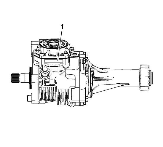
The transfer case oil drain plug (1) is located at the bottom of the assembly to the right side of the rear output shaft.
| General |
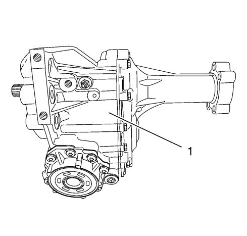
The transfer case (1) is positioned in the right side of the vehicle and bolted to the transmission. Its primary function is to receive power from the transmission and transfer it using helical and hypoid gear sets to the rear differential via the propeller shaft. The internal intermediate shaft transfers power to the right-side front wheel.
The transfer case (1) is fully mechanical with no internal or external electronic controls or sensors.
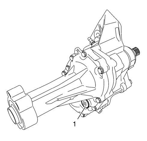
During assembly the transfer case (1) is filled with oil, which then does not require service interval replacement. The correct type of oil must be used when filling. The incorrect type of oil could lead to transfer case damage. Refer to Adhesives, Fluids, Lubricants, and Sealers .
| Housing and Cover |
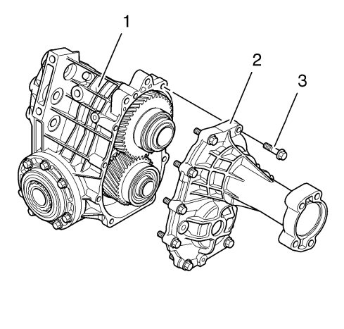
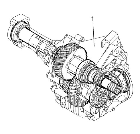
The transfer case housing (1) and rear extension housing (2) are produced from a high-pressure cast aluminium alloy. A number of reinforcement ribs are fitted in suitable locations to strengthen the transfer case assembly. These reinforcement ribs constitute a vital part of the cooling for the transfer case. The transfer case rear extension housing is retained to the transfer case housing with bolts (3). Two dowel pins locate the extension housing to the transfer case housing. The mating surfaces of transfer case housing and rear extension housing are sealed by a press-in-place serviceable seal.
The transfer case assembly is bolted to the transmission with four or five transfer case bolts. For RPO MXE applications, one of the transfer case mounting bolts is accessible via an access hole in the center of the assembly. A locating bushing (2) on the transfer case housing ensures correct installation position for RPO MXE only. The sealing area between the transfer case housing and the transmission is sealed with serviceable O-ring (1). Two opposite radial seals seal the input shaft and prevent transmission and transfer case oil from mixing. If an input shaft seal failure occurs, the transmission and transfer case fluids will not mix as there is a weep hole in the transfer case housing between the two radial seals.
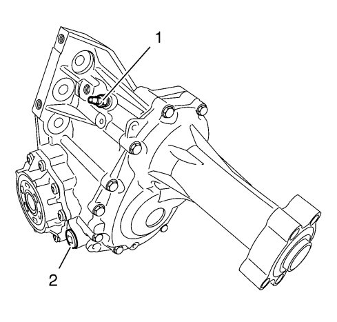
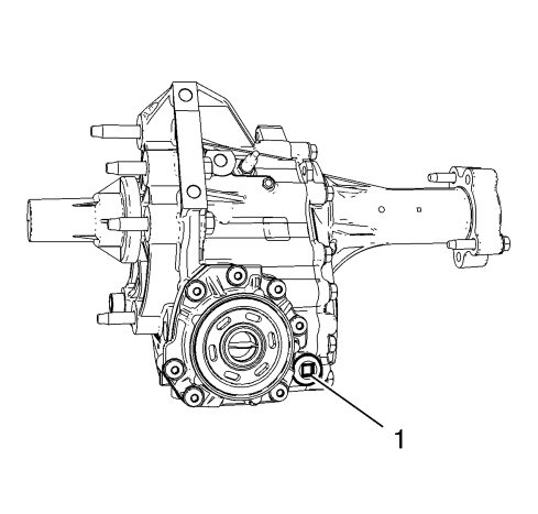
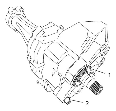
A transfer case vent (1) is located on the top area of the transfer case housing. The vent is mated to a remote vent hose assembly that is routed into the engine compartment. The oil drain plug (2) is magnetic. A mounting bracket retains the output end of the rear extension housing to the engine assembly.
| Bearings and Races |
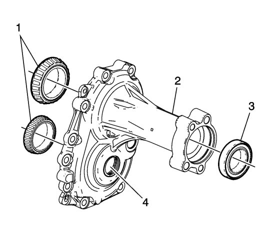
There are tapered bearing races (1) in the transfer case housing and rear extension housing (2) for the input shaft and idler shaft. Gear tooth clearances and bearing preloads are maintained by shims located behind the bearing races. There is a sealed ball bearing type intermediate shaft bearing (3) located in the rear extension housing. The RPO-MXE transfer case rear extension housing has an opening (4) through which one of the transmission-to-transfer case attaching bolts is accessed.
| Input Shaft |
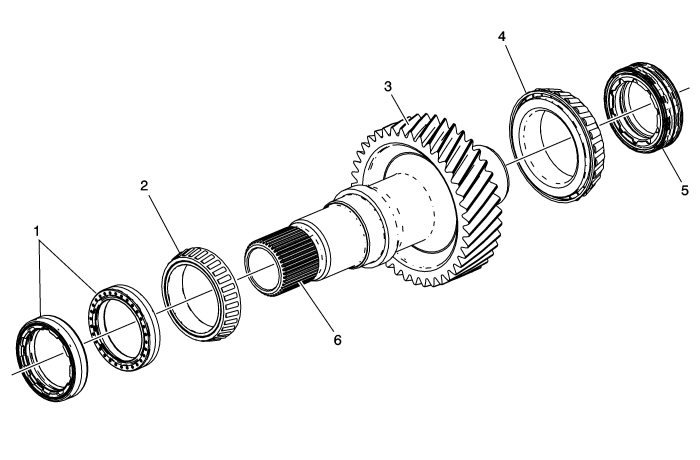
The input shaft splines (6) are mated to and driven by the transmission differential housing. The rotational speed of the input shaft is the same as the transmission output. Installed into the transfer case housing are two opposing input shaft front seals (1). The two input shaft front seals are designed to restrict transmission oil from entering the transfer case as well as restrict transfer case oil from entering the transmission. The opposite or rear end of the input shaft is sealed by a double-lip intermediate shaft seal (5). The intermediate shaft seal (5) is installed into the output end of the rear extension housing and is designed to restrict oil, dirt, and debris from entering the transfer case. The helical gear teeth of the input shaft (3) are engaged to the helical gear teeth of the idler shaft. The input shaft is mounted in two tapered roller bearings (2,4). The bearings are given the correct preload during assembly by means of shims being fitted behind the bearing races in the housing and cover.
| Idler Gear |
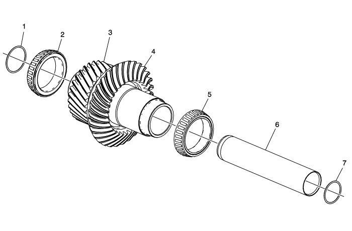
The idler gear consists of a helical gear (3) and a hypoid gear (4), has a hollow center, and is driven by the helical gear on the input shaft.
The idler hypoid gear (4) mates to and drives the hypoid gear on the rear output shaft. The input shaft, idler gear, and rear output shaft gear sets are precision machined and are not serviceable.
The idler gear is mounted in two tapered roller bearings (2 and 5). The bearings are given the correct preload and gears proper clearance during assembly by means of shims being fitted behind the bearing races in the housing and cover. If the shims are removed for any reason, the shims need to be reinstalled to their original locations.
For RPO-MXE applications, there is an additional idler gear shaft (6) located inside and running through the idler gear. The idler shaft is sealed at each end by O-ring seals (1 and 7) within the transfer case and rear extension housings.
| Rear Output Shaft Housing |
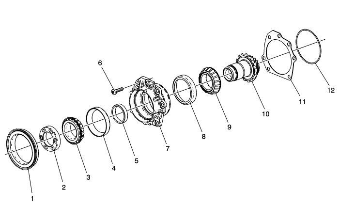
The rear output shaft housing assembly includes an output shaft (10), 2 tapered roller bearings (3 and 9), a rear output shaft seal (1), shaft retaining nut (2), housing (7) and housing seal (12).
The hypoid gear of the rear output shaft is mated to the hypoid gear of the idler shaft. A shim (11) maintains the proper gear contact.
The housing is retained to the transfer case by 7 bolts (6). The only serviceable component within the rear output shaft and housing assembly is the rear output shaft seal (1).
The only serviceable component within the rear output shaft and housing assembly is the rear output shaft seal (3).
The seal is a unitized/cassette type design to include inner and outer metal sleeves and internal sealing rings.
