Case Cover Assembly Assemble
|
|
Case Cover Assembly Assemble
|
|
Fluid Seal Ring Installation
|
Fluid Seal Ring Installation
|
Callout
|
Component Name
|
|
1
|
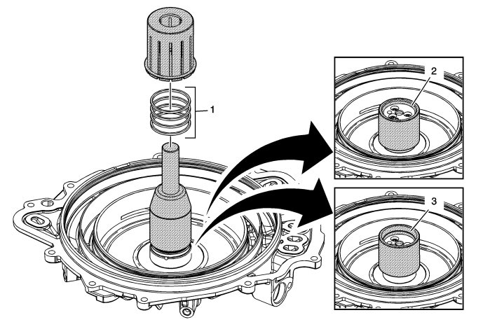
3-5 Reverse and 4-5-6 Clutch Fluid Seal Ring
Procedure
|
1.
|
Place DT 46620-3 which is part of
DT-46620
seal installer over the case cover hub and adjust it so that only the bottom seal ring is exposed.
|
|
2.
|
Place a NEW fluid seal ring onto DT 46620-3 which is part of
DT-46620
seal installer.
|
|
3.
|
Use DT 46620-2 which is part of
DT-46620
seal installer to push the fluid seal ring down over DT 46620-3 which is part of
DT-46620
seal installer into the hub ring groove.
|
|
4.
|
Repeat the above steps to install all 4 seal rings, adjusting DT 46620-3 which is part of
DT-46620
seal installer to the appropriate ring groove.
|
Special Tools
DT 46620
Seal Installer
For equivalent regional tools, refer to
Special Tools
.
|
|
2
|
Small Chamfer Faces Up
 Warning
|
|
Do not force the seal installer down over the seals as this will roll and damage the seals. The large chamfer is designed to fit over the over stretched seal. Use a hand to help shrink the seal if the seal installer is difficult to install over the seal rings.
|
|
|
|
|
|
Procedure
Install DT 46620-1 which is part of
DT-46620
seal installer with the large chamfer end down over the fluid seal rings and leave DT 46620-1 which is part of
DT-46620
seal installer on the seals for at least 60 seconds.
|
|
3
|
Large Chamfer Faces Up
Procedure
|
1.
|
Install DT 46620-1 which is part of
DT-46620
seal installer with the small chamfer end facing down for at least 60 seconds. This will properly size the bottom seal ring.
|
|
2.
|
Leaving DT 46620-1 which is part of
DT-46620
seal installer on the fluid seal rings for an extended period of time could cause a fluid leak on the initial clutch piston circuit until the seal rings warm up and expand to the proper dimension.
|
|
|
2-6 Clutch Piston Installation
|
2-6 Clutch Piston Installation
|
Callout
|
Component Name
|
|
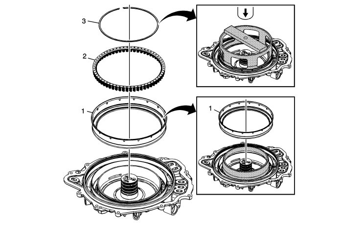
1
|
2-6 Clutch Piston
Procedure
DT-46621
seal protector prevents the piston seal lip from damage over the retaining ring groove during installation. Apply a thin coat of ATF to the O.D. of
DT-46621
seal protector to ease the installation of the piston.
Special Tools
DT-46621
Seal Protector
For equivalent regional tools, refer to
Special Tools
.
|
|
2
|
2-6 Clutch Spring Assembly
|
|
3
|
2-6 Clutch Spring Assembly
Procedure
|
1.
|
Install the retaining ring with the opening positioned to the top of the case cover.
|
|
2.
|
Place the retainer ring inside
DT-46632
spring compressor prior to placing
DT-46632
spring compressor onto the spring.
|
Special Tools
DT-46632
Spring Compressor
For equivalent regional tools, refer to
Special Tools
.
|
|
Low and Reverse Clutch Piston Installation
|
Low and Reverse Clutch Piston Installation
|
Callout
|
Component Name
|
|
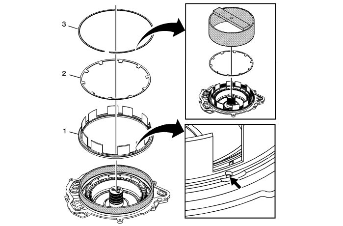
1
|
Low and Reverse Clutch Piston Assembly
Procedure
|
1.
|
Install the L/R piston with the air bleed positioned at the alignment feature on the cover, using
DT-46628-1
seal protector. This will orient the piston fingers with the openings in the case.
|
|
2.
|
DT-46628-1
seal protector prevents the piston seal lip from damage during installation. Apply a thin coat of ATF to the I.D. of
DT-46628-1
seal protector to ease the installation of the piston.
|
Special Tools
DT-46628-1
Piston Seal Protector
For equivalent regional tools, refer to
Special Tools
.
|
|
2
|
Low and Reverse Clutch Spring
|
|
3
|
Low and Reverse Clutch Spring Retaining Ring
|
Note
|
|
Do not align the retainer opening with other retaining ring openings.
|
Special Tools
DT-46628-2
Spring Compressor
For equivalent regional tools, refer to
Special Tools
.
|
|
2-6 and Low-Reverse Piston Function Inspection
|
2-6 and Low-Reverse Piston Function Inspection
|
Callout
|
Component Name
|
|
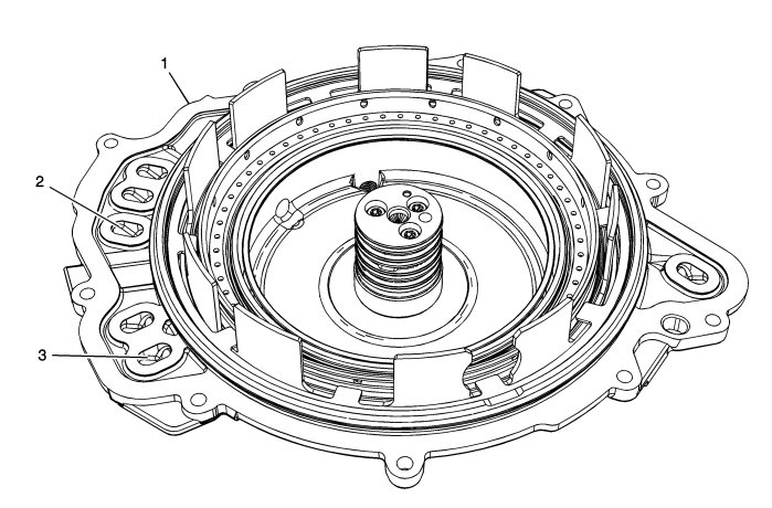
1
|
Case Cover Assembly
|
Note
|
|
The fluid seal rings should be in place and not damaged.
|
|
|
2
|
2-6 Clutch Feed Passage
|
Warning
|
|
Regulate the air pressure to 40 psi maximum. High pressure could cause the piston to over travel and damage the piston seals.
|
|
|
|
|
|
Procedure
Apply shop air to the 2-6 clutch feed. Observe the 2-6 piston movement.
|
Note
|
|
Minimal piston movement and excessive air leaking could indicate damage to the 2-6 piston seals or improper assembly.
|
|
|
3
|
Low and Reverse Clutch Feed Passage
|
Warning
|
|
Regulate the air pressure to 40 psi maximum. High pressure could cause the piston to over travel and damage the piston seals.
|
|
|
|
|
|
Procedure
Apply shop air to the Low and Reverse clutch feed. Observe the Low and Reverse piston movement.
|
Note
|
|
Minimal piston movement and excessive air leaking could indicate damage to the Low and Reverse piston seals or improper assembly.
|
|
|
Input Speed Sensor Installation
|
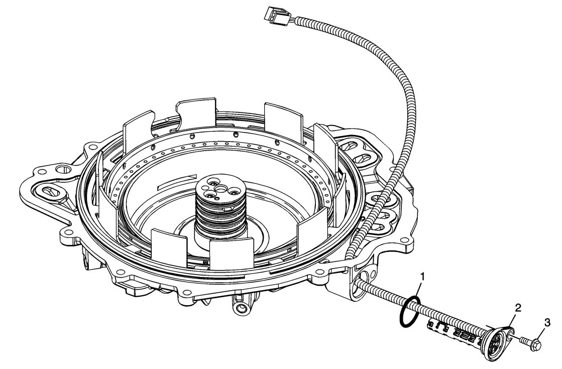
Input Speed Sensor Installation
|
Callout
|
Component Name
|
|
1
|
Input Speed Sensor Seal
|
|
2
|
A/Trans Input Speed Sensor Assembly
|
|
3
|
A/Trans Input Speed Sensor Bolt M6 x 25
Refer to
Fastener Caution
.
Procedure
Apply threadlocker or equivalent to the input speed sensor bolt. Refer to
Adhesives, Fluids, Lubricants, and Sealers
.
|
Note
|
|
The seal is coated with a dry lubricant. If the coating is missing, lubricate the seal with automatic transmission fluid prior to installation.
|
Tighten
9 Nm (7 lb ft)
|
