PRE-RELEASE
Control Valve Body Assembly Installation
| Control Valve Body Assembly Installation |
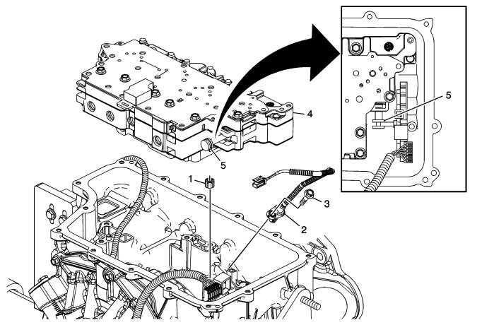
Output Speed Sensor and Valve Body Installation
| Callout | Component Name | |||||||||
| 1 | 1-2-3-4 Clutch Fluid Passage Seal | |||||||||
| 2 | A/Trans Output Speed Sensor Assembly | |||||||||
| 3 |
A/Trans Output Speed Sensor Assembly Bolt M6 x 25
Refer to
Fastener Caution
.
Tighten12 Nm (9 lb ft) |
|||||||||
| 4 | Control Valve Body Assembly | |||||||||
| 5 |
Manual Valve
Special ToolsDT 41229 Manual Shaft Pin Installer For equivalent regional tools, refer to Special Tools . |
|||||||||
| Control Valve Body Bolts Installation |
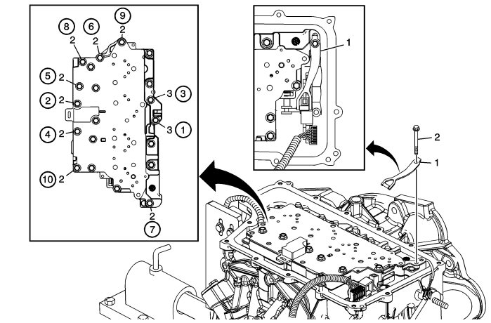
Control Valve Body Bolts Installation
| Callout | Component Name | ||||||
| 1 |
Manual Shaft Detent Assembly
|
||||||
| 2 |
Control Valve Body Bolt M6 x 65 (Qty: 8)
Refer to
Fastener Caution
.
ProcedureTighten in sequence.Tighten12 Nm (9 lb ft). |
||||||
| 3 |
Control Valve Body Bolt M6 x 55 (Qty: 2)
ProcedureTighten in sequence.Tighten12 Nm (9 lb ft). |
||||||
| Filter Plate Installation |
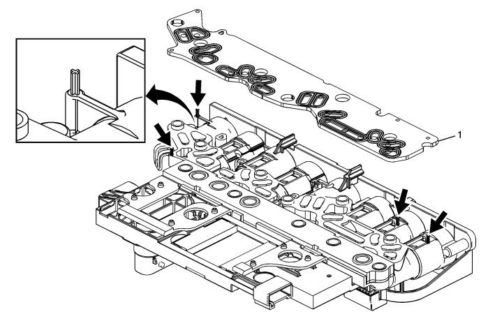
Filter Plate Installation
| Callout | Component Name | ||||||||||||||
| 1 |
Control Solenoid Valve Assembly Filter Plate
|
||||||||||||||
 Warning
| Control Solenoid (w/Body and TCM) Valve Assembly Installation |
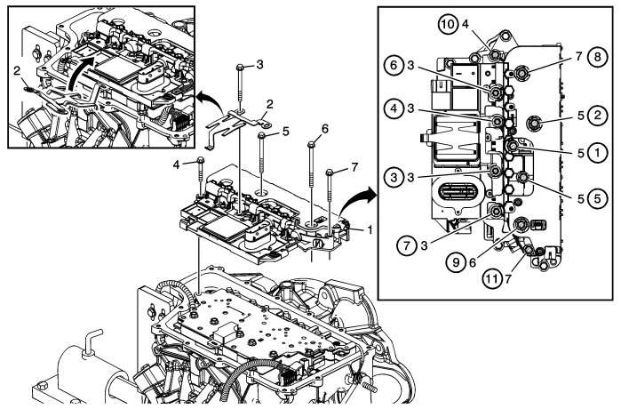
Control Solenoid (w/Body and TCM) Valve Assembly Installation
| Callout | Component Name | |||||||||
Refer to
Fastener Caution
.
Preliminary ProceduresInstall all bolts before tightening, then tighten in sequence to 12 Nm (9 lb ft). |
||||||||||
| 1 |
Control Solenoid (w/Body and TCM) Valve Assembly
|
|||||||||
| 2 |
Control Solenoid Valve Spring
|
|||||||||
| 3 | Control Valve Body Bolt M6 x 80 (Qty: 4) | |||||||||
| 4 | Control Valve Body Bolt M6 x 55 (Qty: 1) | |||||||||
| 5 | Control Valve Body Bolt M6 x 95 (Qty: 3) | |||||||||
| 6 | Control Valve Body Bolt M6 x 42 (Qty: 1) | |||||||||
| 7 | Control Valve Body Bolt M6 x 65 (Qty: 2) | |||||||||
| Wire Routing and Connector Locations |
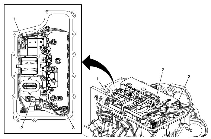
Wire Routing and Connector Locations
| Callout | Component Name |
Preliminary ProceduresRoute all wires as shown. |
|
| 1 | Shift Position Switch Connector |
| 2 | Output Speed Sensor Connector |
| 3 | Input Speed Sensor Connector |
| Control Valve Body Cover Installation |
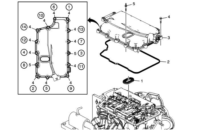
Control Valve Body Cover Installation
| Callout | Component Name | ||||||
| 1 |
Control Valve Body Cover Wiring Connector Hole Seal
|
||||||
| 2 | Control Valve Body Cover Assembly Gasket | ||||||
| 3 | Control Valve Body Cover Assembly | ||||||
| 4 |
Control Valve Body Cover Bolt M6 x 30 (Qty: 12)
Refer to
Fastener Caution
.
ProcedureTighten in sequence.Tighten12 Nm (9 lb ft). |
||||||
| 5 |
Control Valve Body Cover Stud M6 x 30 (Qty: 2)
ProcedureTighten in sequence.Tighten12 Nm (9 lb ft). |
||||||
