PRE-RELEASE
Front Brake Rotor Replacement
| Front Brake Rotor Replacement |
Special Tools
| • |
CH-41013
Rotor Resurfacing Kit
|
|
| • |
CH-42450-A
Wheel Hub Resurfacing Kit
|
|
For equivalent regional tools, refer to Special Tools .
| Removal Procedure |
Refer to Brake Dust Warning .
| 1. |
Raise and support the vehicle. Refer to
Lifting and Jacking the Vehicle
.
|
|
| 2. |
Remove the tire and wheel assembly. Refer to
Tire and Wheel Removal and Installation
.
|
|
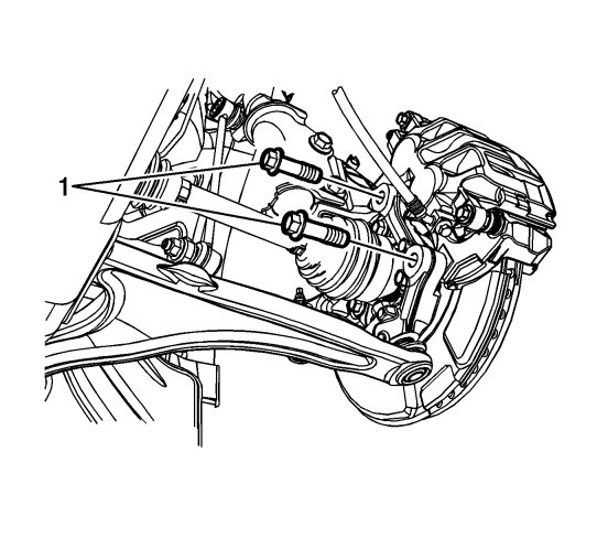
| 3. |
Remove the brake caliper bracket bolts (1).
|
|
| 4. |
Without disconnecting the brake caliper hose, remove the brake caliper and bracket assembly and support with heavy mechanics wire or equivalent. |
|||||||||
 Warning
| 5. |
If installing the original brake rotor, mark the relationship of the rotor to the wheel hub.
|
|
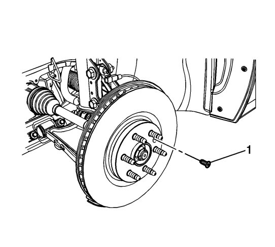
| 6. |
Remove the brake rotor bolt (1).
|
|
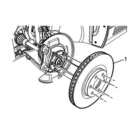
| 7. |
Remove the brake rotor (1).
|
|
| Installation Procedure |
| 1. |
If installing a new brake rotor, clean the friction surfaces of the brake rotor with denatured alcohol.
|
|
| 2. |
Using the
CH-42450-A
wheel hub resurfacing kit , thoroughly clean any rust or corrosion from the mating surface of the hub/axle flange.
|
|
| 3. |
Using the
CH-41013
Rotor Resurfacing Kit, thoroughly clean any rust or corrosion from the mating surface of the rotor to the hub/axle flange.
|
|
| 4. |
Install the brake rotor (1).
If installing the original brake rotor, align the rotor to the wheel hub as noted during removal.
|
|
| 5. |
Refer to
Fastener Caution
.
Install the brake rotor bolt (1) and tighten to 9 Nm (80 lb in) .
|
|
| 6. |
After installing the brake rotor, measure the assembled lateral runout (LRO) of the brake rotor. Refer to
Brake Rotor Assembled Lateral Runout Measurement
.
|
|
| 7. |
If the brake rotor assembled LRO measurement exceeds specification, bring the LRO to within specification. Refer to
Brake Rotor Assembled Lateral Runout Correction
.
|
|
| 8. |
Prepare the brake caliper bracket bolts and the bracket threaded holes for assembly:
|
|
| • |
Thoroughly clean the residue from the bolt threads with denatured alcohol or equivalent and allow to dry.
|
| • |
Thoroughly clean the residue from the threaded holes with denatured alcohol or equivalent and allow to dry.
|
| • |
Apply threadlocker to 2/3 of the threaded length of the caliper bracket bolts. Refer to
Adhesives, Fluids, Lubricants, and Sealers
.
|
| • |
Ensure there are no gaps in the threadlocker along the length of the filled area of the bolts.
|
| • |
Allow the threadlocker to cure approximately 10 minutes before installation.
|
| 9. |
Position the brake caliper and bracket assembly to the vehicle.
|
|
| 10. |
Install the brake caliper bracket bolts (1) and tighten to
110 Nm (81 lb ft)
.
|
|
| 11. |
Install the tire and wheel assembly. Refer to
Tire and Wheel Removal and Installation
.
|
|
