PRE-RELEASE
Power Brake Booster Vacuum Check Valve and Hose Replacement (LF1)
| Power Brake Booster Vacuum Check Valve and Hose Replacement (LF1) |
| Removal Procedure |
| 1. |
With the engine OFF, apply and release the brake pedal several times until the brake pedal becomes firm to deplete the power vacuum brake booster vacuum reserve.
|
|
| 2. |
Remove the intake manifold cover. Refer to
Intake Manifold Cover Replacement
.
|
|
| 3. |
If equipped with the master cylinder heat shield, remove the master cylinder heat shield nuts (1). 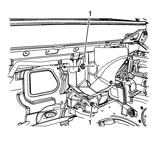
|
|||||||
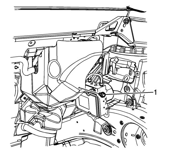
| 4. |
Remove the master cylinder heat shield bolt (1).
|
|
| 5. |
Remove the master cylinder heat shield.
|
|
| 6. |
Disconnect the power vacuum brake booster vacuum sensor electrical connector.
|
|
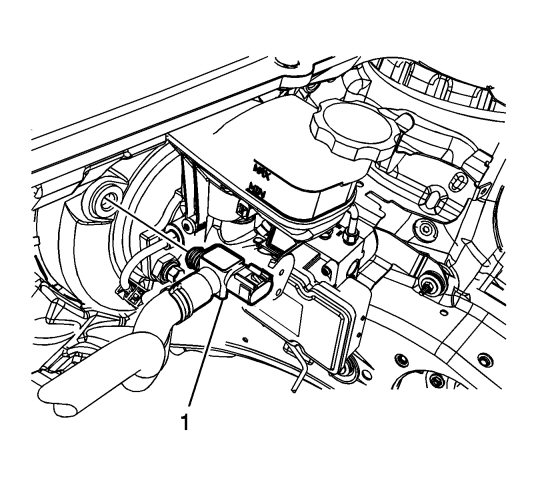
| 7. |
Remove the vacuum sensor (1) and power brake booster vacuum hose assembly from the power vacuum brake booster.
|
|
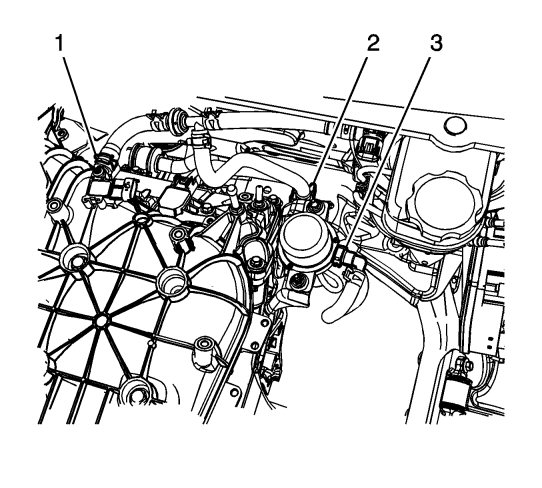
| 8. |
Release the spring clamp (1) and remove the power brake booster vacuum hose from the intake manifold vacuum port.
|
|
| 9. |
Release the power brake booster vacuum hose from the routing clip (2) on the power brake booster auxiliary pump.
|
|
| 10. |
Disconnect the power brake booster vacuum hose quick connect (3).
|
|
| 11. |
Remove the power brake booster vacuum hose and check valve assembly.
|
|
| Installation Procedure |
| 1. |
Install the power brake booster vacuum hose and check valve assembly.
|
|
| 2. |
Position the power brake booster vacuum hose to the intake manifold vacuum port and install the spring clamp (1). |
|||||||
| 3. |
Install the power brake booster vacuum hose to the routing clip (2) on the power brake booster auxiliary pump.
|
|
| 4. |
Connect the power brake booster vacuum hose quick connect (3).
|
|
| 5. |
Install the vacuum sensor (1) and power brake booster vacuum hose assembly to the power vacuum brake booster.
|
|||||||
| 6. |
Connect the power brake booster vacuum sensor electrical connector.
|
|
| 7. |
Install the master cylinder heat shield, if equipped.
|
|
| 8. |
Refer to
Fastener Caution
.
Install the master cylinder heat shield bolt (1) and tighten to 10 Nm (89 lb in) . |
|
| 9. |
Install the master cylinder heat shield nuts (1) and tighten to 25 Nm (18 lb ft) .
|
|||||||
| 10. |
Install the intake manifold cover. Refer to
Intake Manifold Cover Replacement
.
|
|
