PRE-RELEASE
Front Wheelhouse Panel Replacement
| Front Wheelhouse Panel Replacement |
| Removal Procedure |
| 1. |
See
Approved Equipment for Collision Repair Warning
and
Handling of Glass and Sheet Metal Warning
Disable the supplemental inflatable restraint (SIR) system. Refer to SIR Disabling and Enabling . 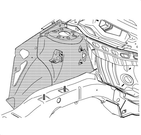
|
|
| 2. |
Disconnect the negative battery cable. Refer to
Battery Negative Cable Disconnection and Connection
.
|
|
| 3. |
Remove all related panels and components.
|
|
| 4. |
Repair as much of the damage as possible to factory specifications. Refer to
Dimensions - Body
.
|
|
| 5. |
Note the location and remove the sealers and anti-corrosion materials from the repair area, as necessary. Refer to
Anti-Corrosion Treatment and Repair
.
|
|
| 6. |
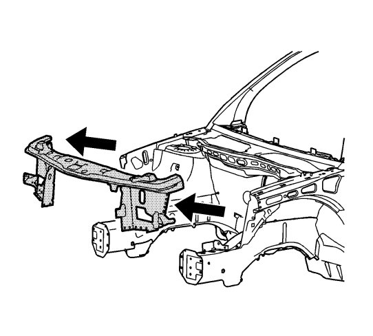
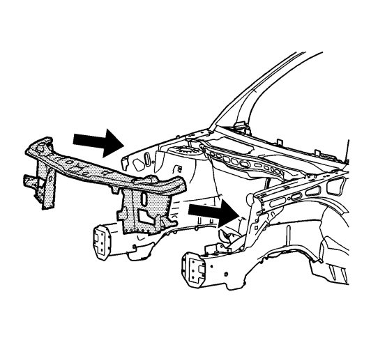
Remove the front tie bar. Refer to
Front End Upper Tie Bar Replacement
.
|
|
| 7. |
Locate and drill out all factory welds. Note the number and location of the welds for installation of the front wheelhouse. 
|
|||||||
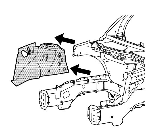
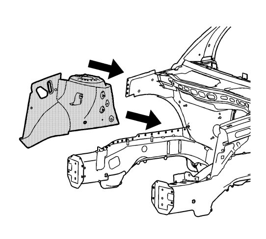
| 8. |
Remove the damaged front wheelhouse.
|
|
| Installation Procedure |
| 1. |
Drill 8 mm (5/16 in) plug weld holes in the service part as necessary in the locations noted from the original panel. 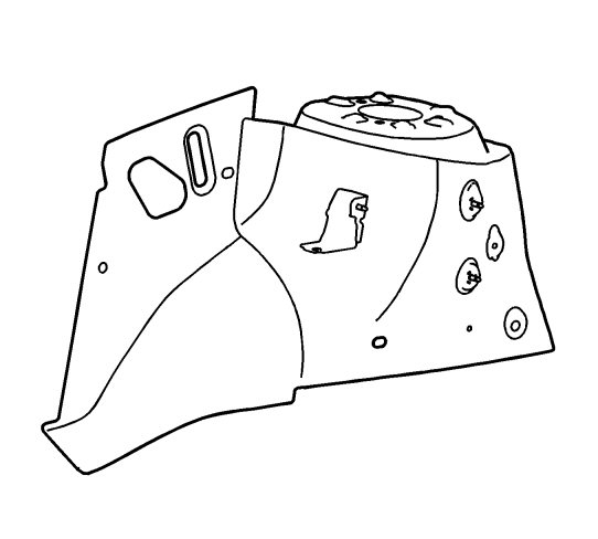
|
||||||||||
| 2. |
Prepare all mating surfaces as necessary.
|
|
| 3. |
Apply GM-approved Weld-Thru Coating or equivalent to all mating surfaces.
|
|
| 4. |
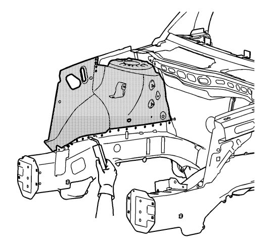
Position the front wheelhouse to the vehicle using 3-dimensional measuring equipment. Clamp the front wheelhouse into place.
|
|
| 5. |
Plug weld accordingly.
|
|
| 6. |
Replace the tie bar. Refer to
Front End Upper Tie Bar Replacement
.
|
|
| 7. |
Clean and prepare all welded surfaces.
|
|
| 8. |
Apply the sealers and anti-corrosion materials to the repair area, as necessary.
|
|
| 9. |
Paint the repair area. Refer to
Basecoat/Clearcoat Paint Systems
.
|
|
| 10. |
Install all related panels and components.
|
|
| 11. |
Connect the negative battery cable. Refer to
Battery Negative Cable Disconnection and Connection
.
|
|
| 12. |
Activate the SIR system. Refer to
SIR Disabling and Enabling
.
|
|
