Cylinder heads, both banks (in situ)
|
|
Cylinder heads, both banks (in situ)
|
 Warning
|
|
Removal of the fuel rail involves partial dismantling of the car's fuel system. The following points must therefore be observed in connection with this work:
|
|
•
|
Make sure a class BE fire extinguisher is close to hand! Consider the risk of sparking, e.g. when breaking circuits, short-circuits etc.
|
|
•
|
Absolutely No Smoking!
|
|
•
|
Ensure that there is a good exchange of air. If approved ventilation for the extraction of fuel fumes is available, this should be used.
|
|
•
|
Wear protective gloves! Prolonged exposure of the hands to fuel can cause irritation to the skin.
|
|
•
|
Wear protective goggles.
|
|
|
|
|
|
|
Important
|
|
Be particulary observant regardning cleanliness when working on the fuel system. Loss of function may occur due to very small particles. Prevent dirt and grime from entering the fuel system by cleaning the connections and plugging pipes and lines during disassembly. Use 82 92 948 Plugs, A/C system assembly. Keep components free from contaminants during storage.
|
|
|
|
1.
|
Undo the cap on the expansion tank.
|
|
2.
|
Remove the intake manifold with mass air flow sensor from the turbocharger.
|
|
3.
|
Remove the upper engine cover.
|
|
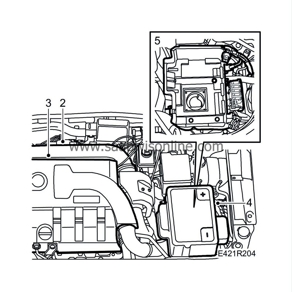
4.
|
Remove the battery cover and battery. Undo and move aside the fuse holder.
|
|
5.
|
Remove the battery tray.
|
|
6.
|
Raise the car and remove the lower engine cover and front spoiler plate.

|
|
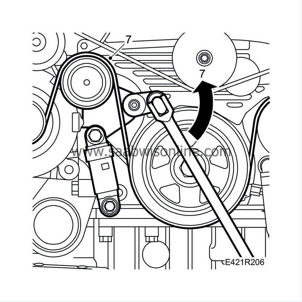
7.
|
Slowly and carefully relieve the tension on the multigroove V-belt and remove it. Slightly loosen the lower generator bolt. Mark the belt's direction of rotation for refitting.
|
|
8.
|
Place a suitable receptacle under the car and drain the cooling system. Close the drain cock.
|
|
9.
|
Cut the cable tie of the oil level sensor.
|
|
10.
|
Remove the front bolt on the front torque arm.

|
|
11.
|
Disconnect the charge air pipe from the charge air cooler.
|
|
12.
|
Remove the bolts to the exhaust pipe bracket and the nuts on the exhaust pipe joint.

|
|
13.
|
Lower the car to the floor.

|
|
14.
|
Remove the charge air hose and pipe from the upper intake manifold.
|
|
15.
|
Remove the catalytic converter.
|
|
16.
|
Cut the cable tie on the radiator hose and remove the upper radiator hose.
|
|
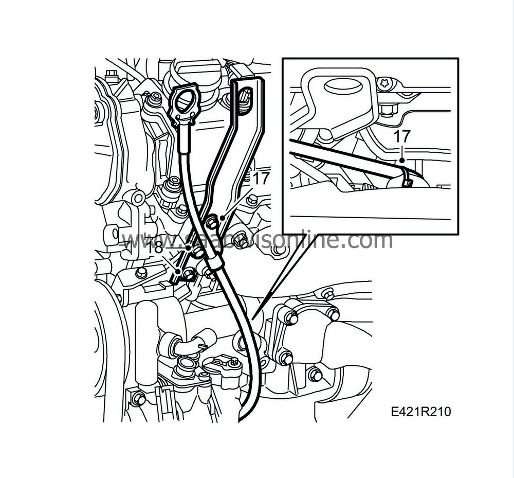
17.
|
Detach the connector and cable tie from the dipstick. Remove the dipstick.
|
|
18.
|
Remove the upper bolt of the lifting eye and loosen the lower one. Move aside the lifting eye.
|
|
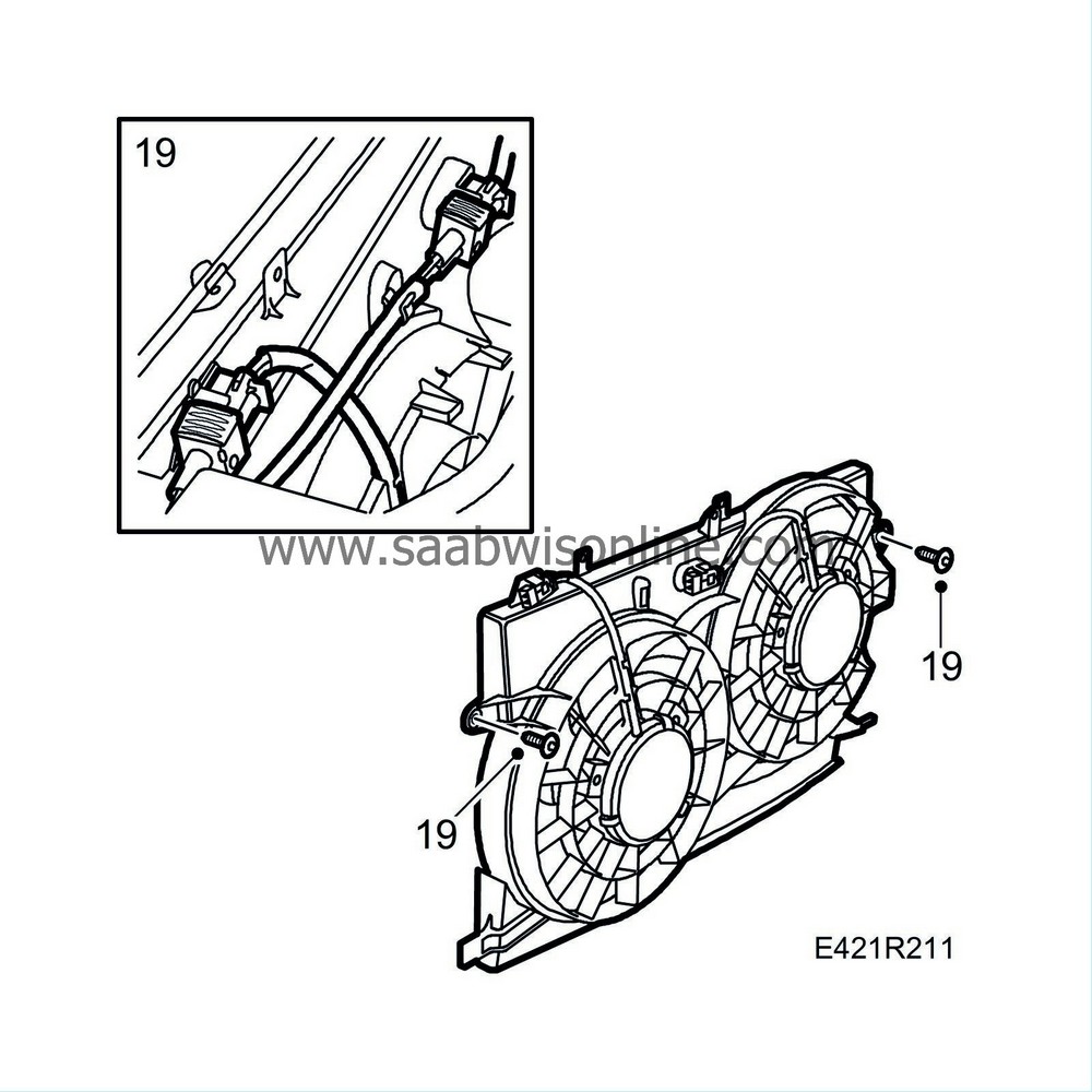
19.
|
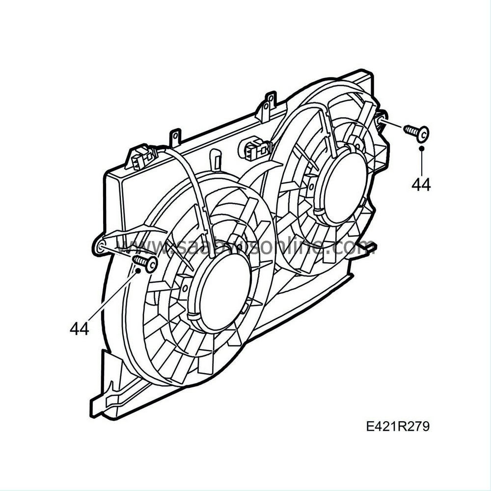
Unplug the connectors, cut the cable tie and remove the fan cowling.
|
|
20.
|
Remove the lower bolt and remove the lifting eye.
|
|
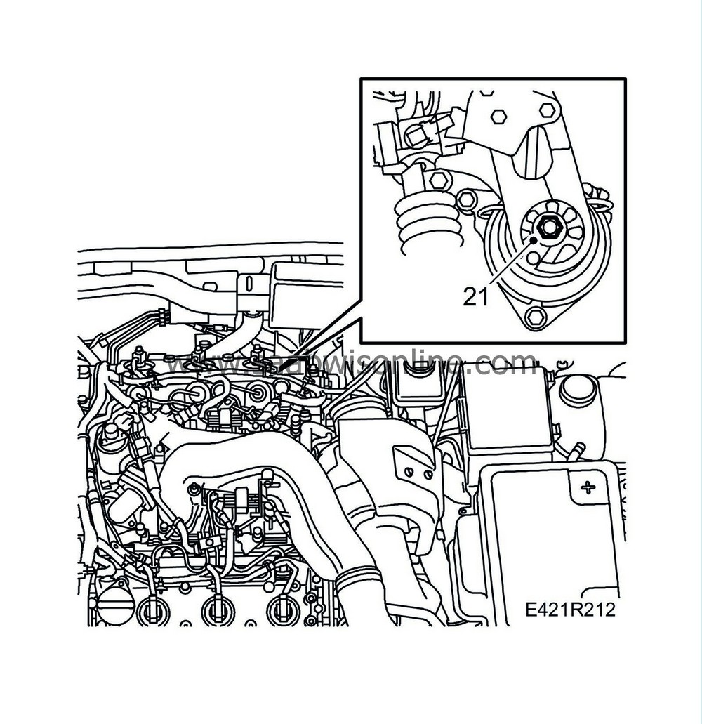
21.
|
Remove the nut on the rear engine mounting.
|
|
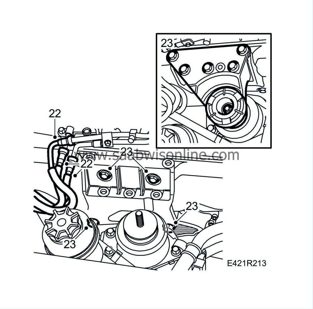
22.
|
Undo the quick-release couplings on the fuel lines. Use a cloth to catch any fuel spill.
|
|
23.
|
Take up the weight of the engine using a jack. Remove the right-hand engine mounting with the bracket and engine pad. Raise the engine slightly and remove the engine bracket bolts.
|
|
24.
|
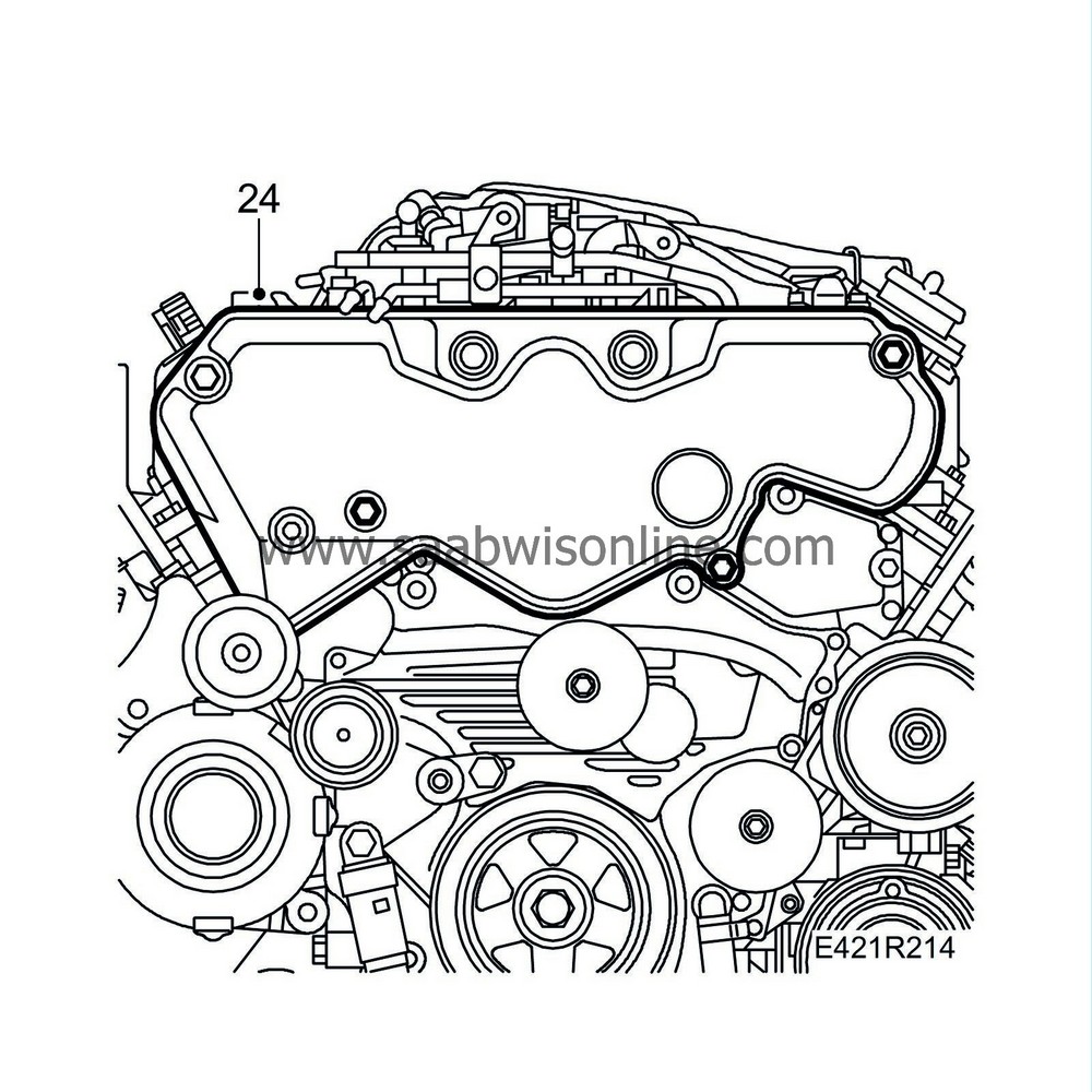
Remove the timing belt cover.
|
|
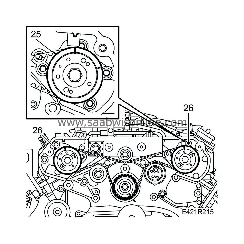
25.
|
Zero the engine, aligning the crankshaft pulley, camshaft pulleys and fuel pump pulley with the markings on the engine.
|
|
26.
|
If the markings on the belt are unclear, remark the belt to correspond with the marks on the pulleys.
|
|
27.
|
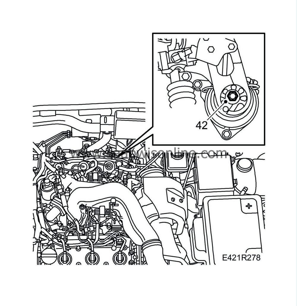
Insert a 6 mm drill bit or similar into the hole in the tensioner pulley and turn it slowly and carefully to relieve the pressure. Remove the tensioner pulley by undoing the bolt and simultaneously withdrawing the pulley.

|
|
28.
|
Remove the timing belt and idler pulley.
|
|
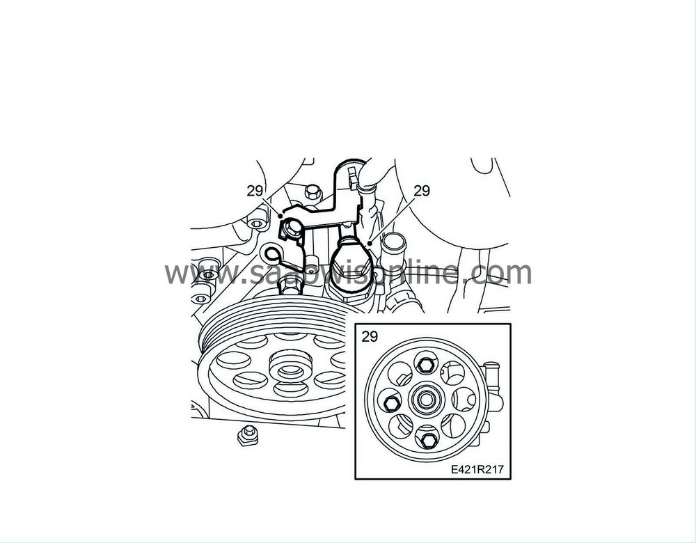
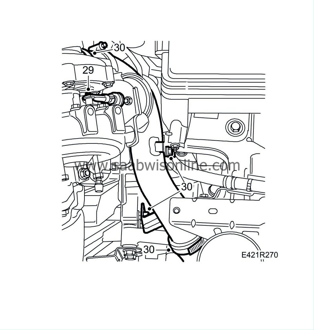
29.
|
Remove the power steering pump with bracket.
|
|
30.
|
Unplug the connectors, remove the cable rails and move aside the engine harness.

|
|
31.
|
Remove the upper intake manifold and the turbocharger's bracket.
|
|
32.
|
Remove the turbocharger heat shield.
|
|
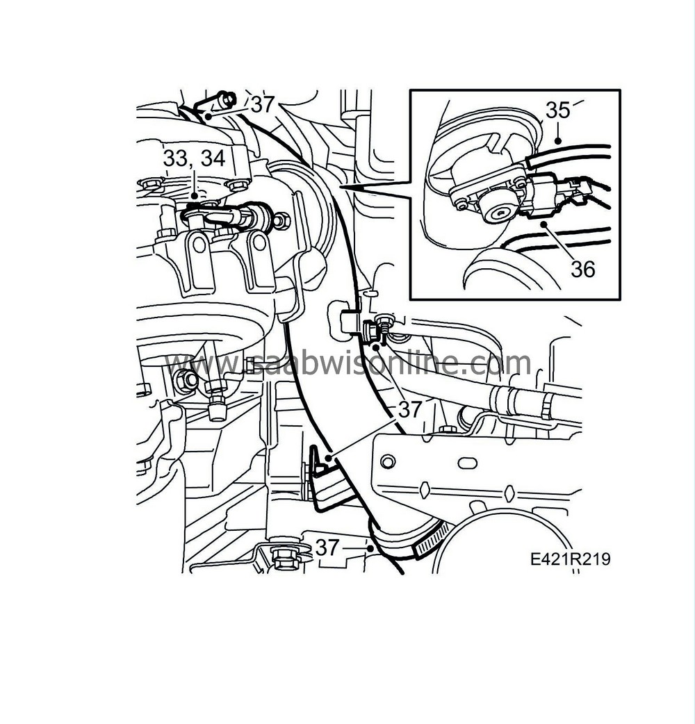
33.
|
Remove the clip using tool 8394538.
|
|
34.
|
Remove the control rod of the diaphragm unit from the turbocharger shaft.
|
|
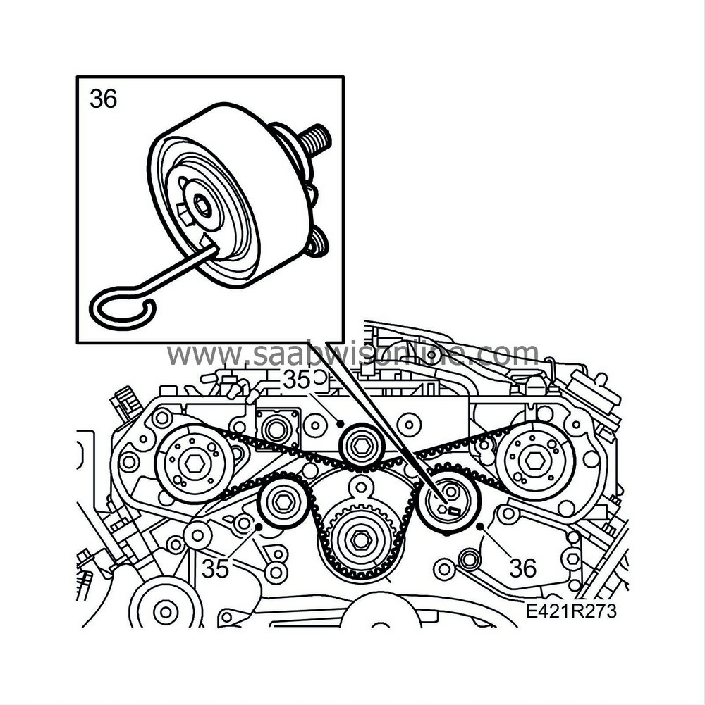
35.
|
Remove the vacuum hose.
|
|
36.
|
Unplug the connector.
|
|
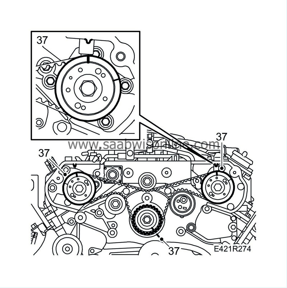
37.
|
Detach the turbo delivery pipe from the turbo unit.
|
|
38.
|
Remove the oil and coolant pipes and the vacuum box from the turbo unit.

|
|
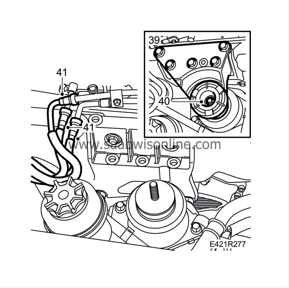
39.
|
Remove the turbo unit.
|
|
40.
|
Remove the fuel pipe and the fuel rail.

|
Warning
|
|
Due to the risk of cuts from the sharp metal edges of the heat shields, protective gloves are to be worn.
|
|
|
|
|
|
|
|
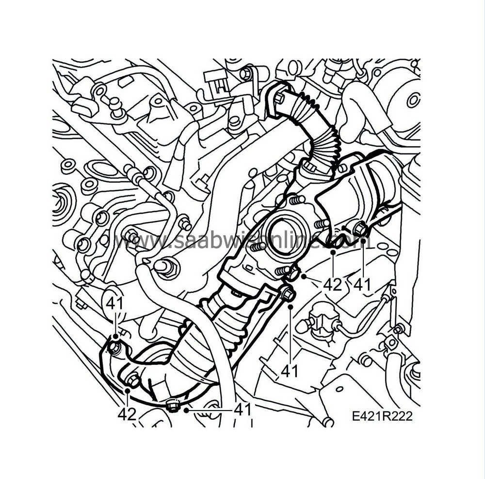
41.
|
Remove the heat shield from over the exhaust manifold. Lower the jack slightly to remove the rear heat shield.
|
|
42.
|
Remove the pipe connecting the cylinder banks to each other as a unit.
|
|
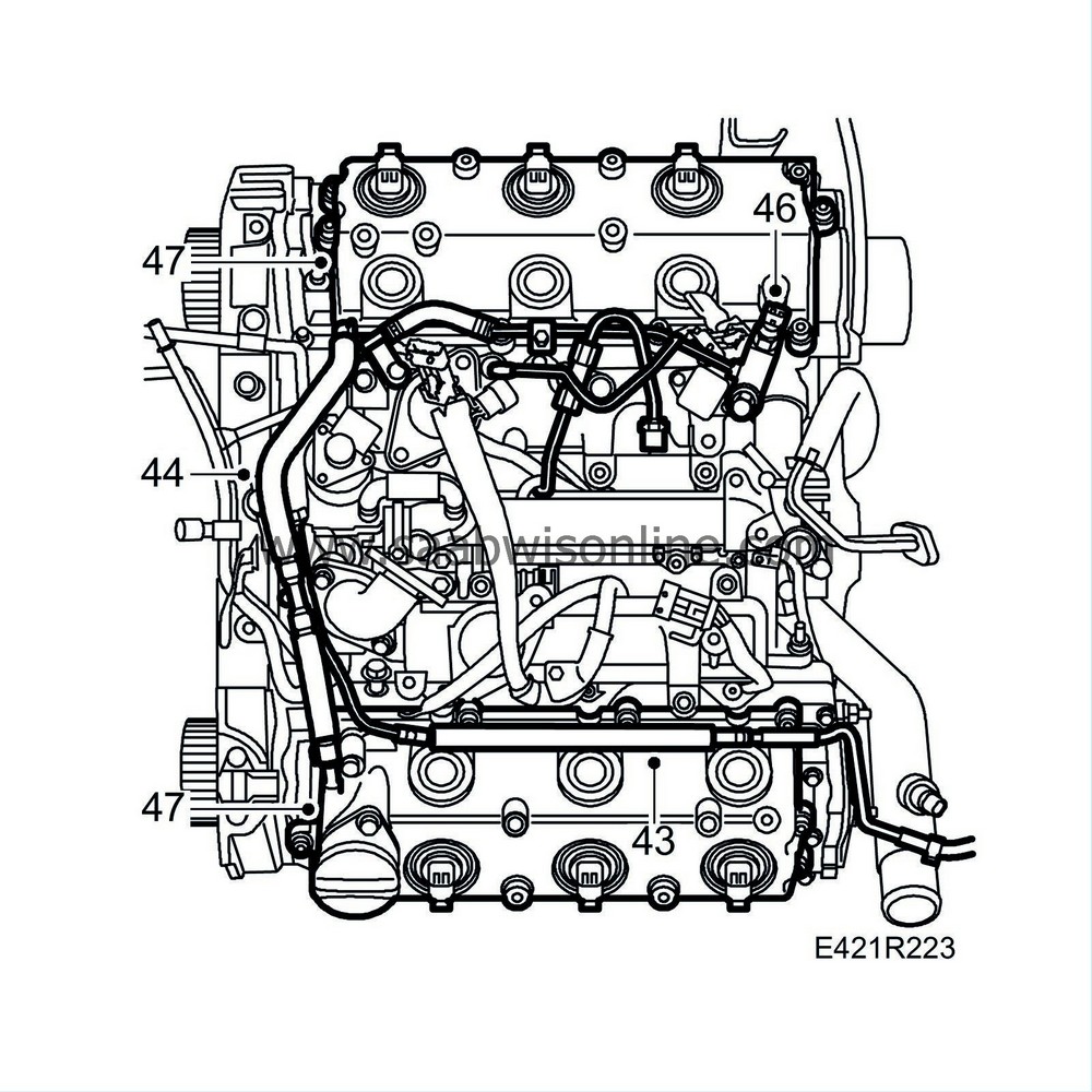
43.
|
Remove the coolant pipe with bracket from the camshaft cover.
|
|
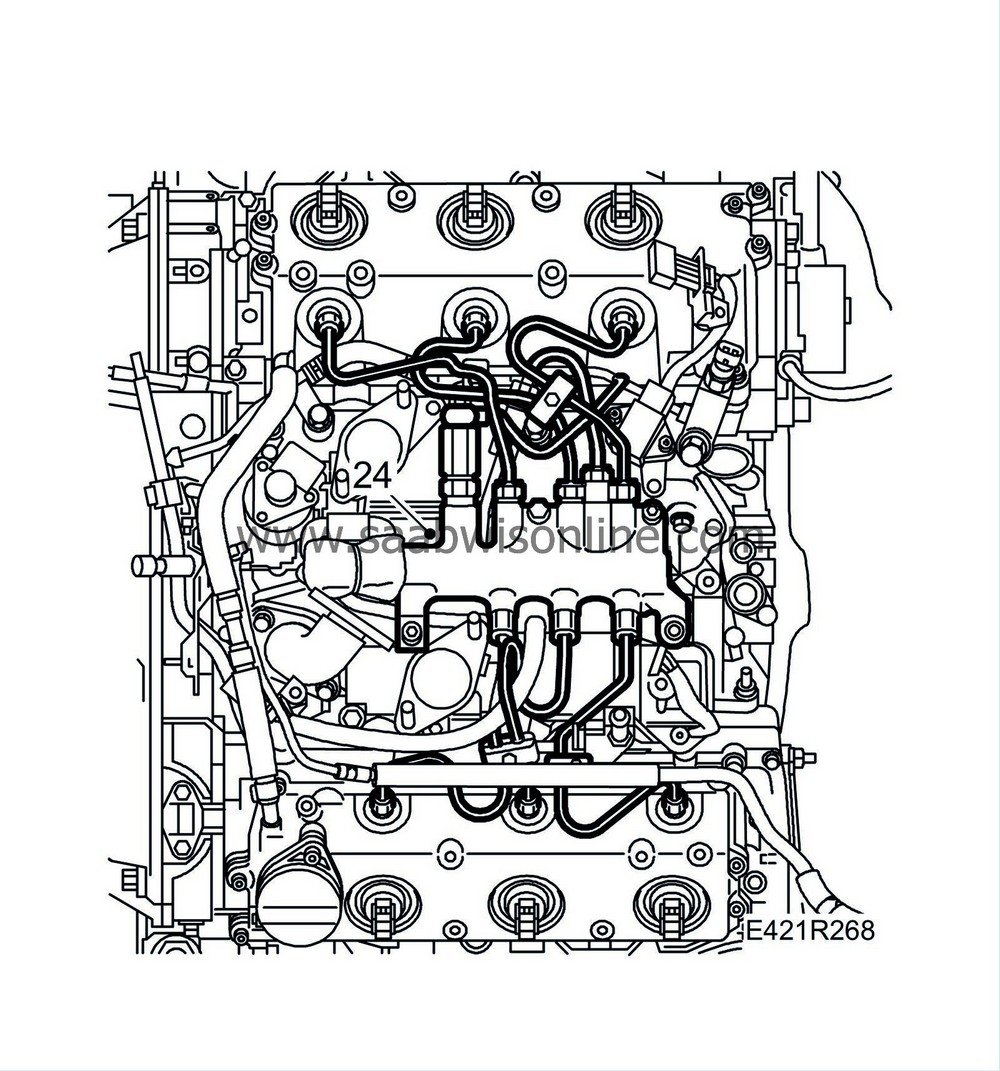
44.
|
Remove the crankcase ventilation hoses.
|
|
45.
|
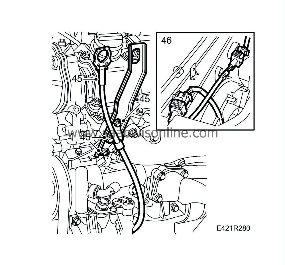
Remove the fuel return pipe from the rear and front cylinder banks.
|
|
46.
|
Detach the fuel feed pipe and the return fuel pipe. Remove the holders for the fuel pipe from the rear camshaft holder frame.
|
|
47.
|
Remove the camshaft covers.
|
Warning
|
|
Release the pressure in the fuel system before starting work. Cover the fuel connections with a rag to protect against spurting fuel.
|
|
|
|
|
|
|
|
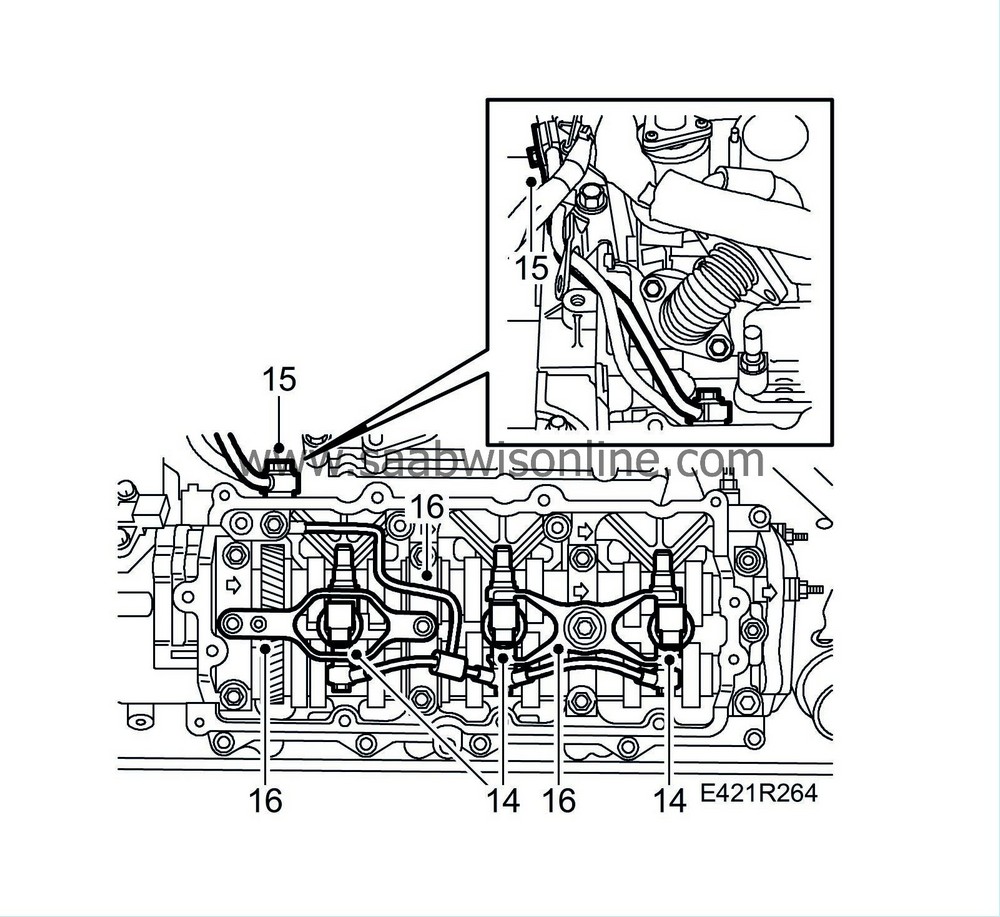
48.
|
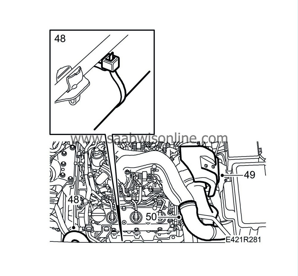
Undo the banjo connection in the rear of the camshaft holder frame. Remove the injector holders.

|
|
49.
|
Remove the injectors and the fuel return pipes.
|
|
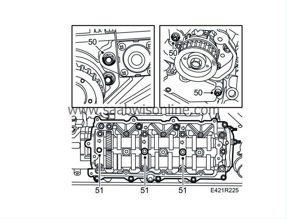
50.
|
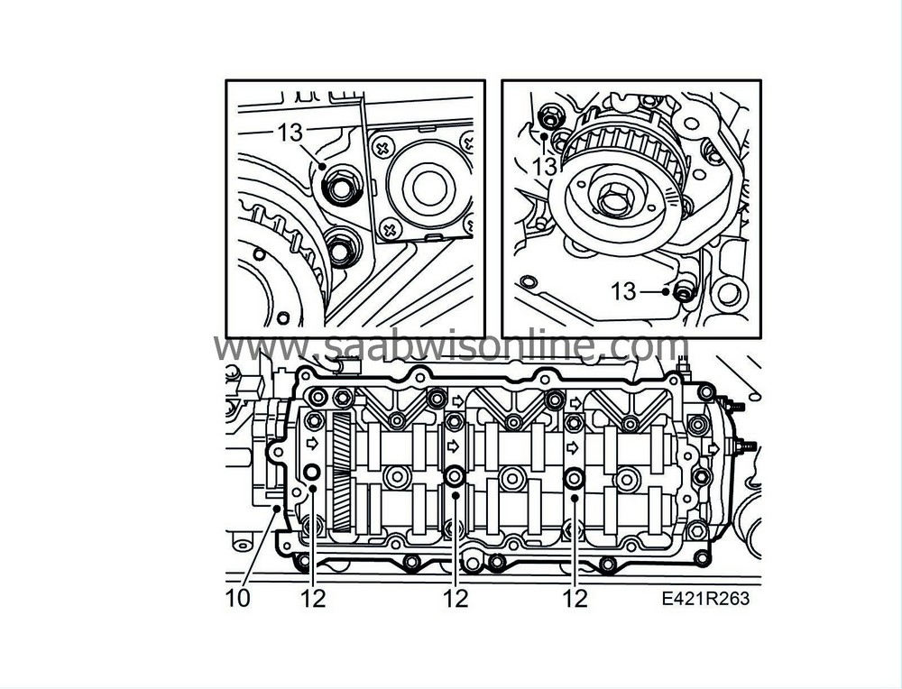
Remove one bolt from the cover at each timing belt gear and one bolt under the cover on the front bank.
|
|
51.
|
Remove the studs securing the holders to the injectors.
|
|
52.
|
Detach the vacuum pump hoses and remove the rear and front camshaft holder frames.
|
|
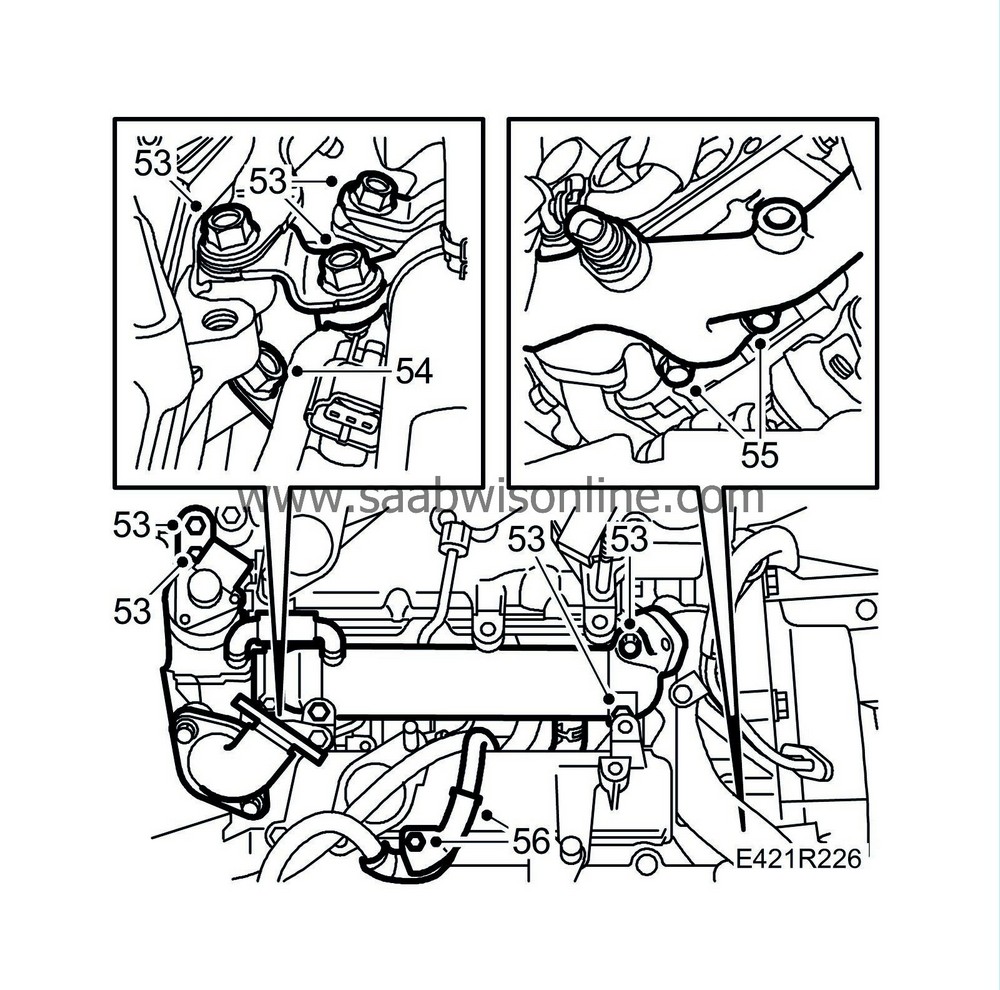
53.
|
Remove the bolts securing the EGR valve with cooler pipe. Move the entire unit aside.
|
|
54.
|
Remove the bolts holding the crankshaft ventilation pipe against the front bank's intake manifold.
|
|
55.
|
Remove the bolts from the coolant pipe against the cylinder head.
|
|
56.
|
Remove the cable duct on the front intake manifold.
|
|
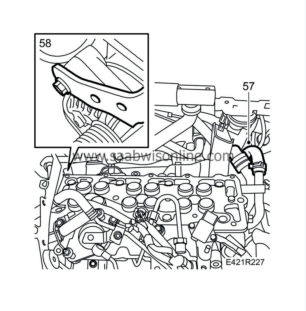
57.
|
Remove the coolant hoses from the rear cylinder bank and the bolt of the lower coolant pipe.
|
|
58.
|
Remove the bolt on the upper bracket of the generator.
|
|
59.
|
Remove the cylinder heads from the rear and front banks with exhaust manifold and intake manifold.

|
|
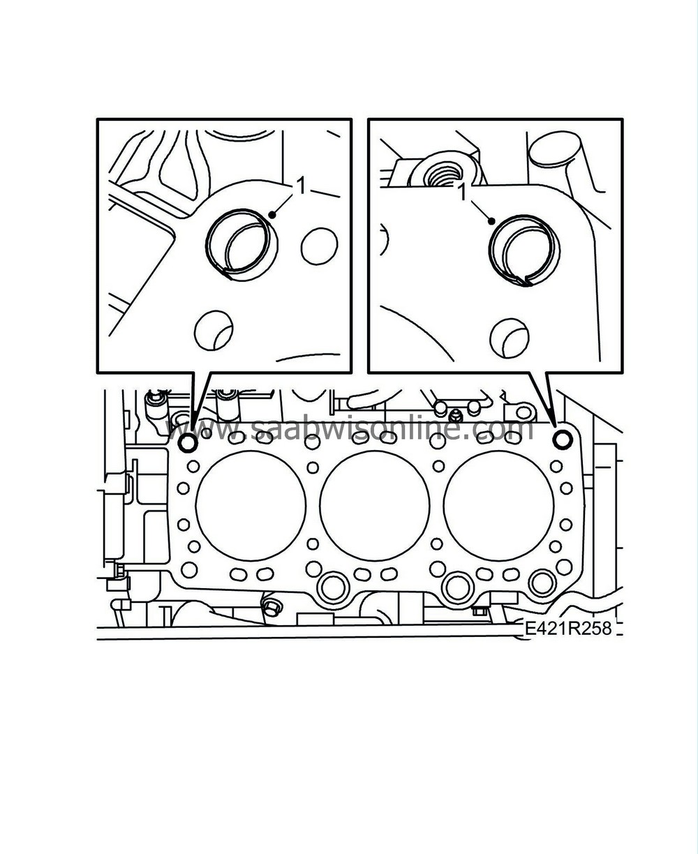
1.
|
Clean the sealing surfaces and the combustion chamber. Blow the bolt holes clean using compressed air. Make sure that the guide rings are correctly positioned in the cylinder block.
|
|
2.
|
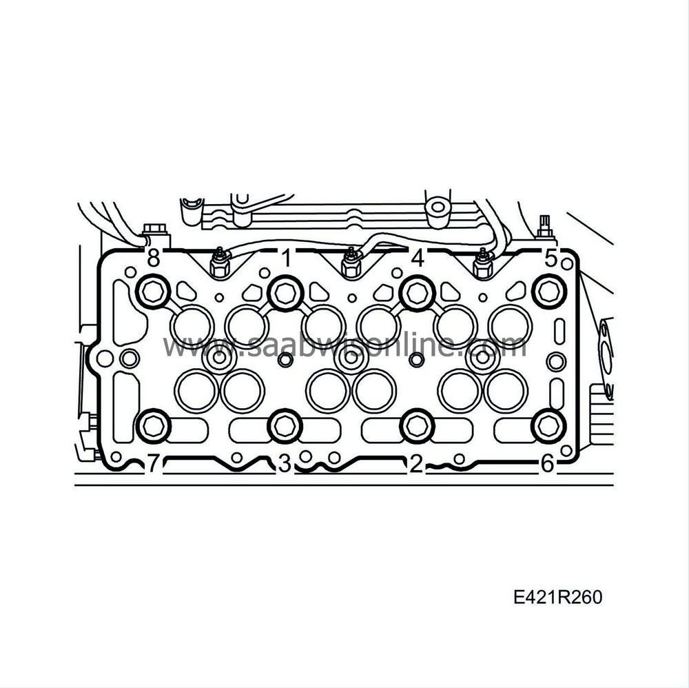
Fit the cylinder heads using new gaskets and new bolts. Note the different bolt lengths. Check that the gasket has correct graduation and marking (L=front cylinder bank) as illustrated. Tighten the bolts following the order below.
Tightening torque, short bolts
Step I: 39 Nm (29 lbf ft)
Step II: Tighten a further 110°
Step III: Tighten a further 110°
Tightening torque, long bolts
Step I: 39 Nm (29 lbf ft)
Step II: Tighten a further 130°
Step III: Tighten a further 130°

|
|
3.
|
Fit the bolt on the upper bracket of the generator.
Tightening torque: 28 Nm (21 lbf ft)
|
|
4.
|
Fit the coolant hoses to the rear cylinder bank.
|
|
5.
|
Fit the cable duct on the front intake manifold.
|
|
6.
|
Fit the bolts to the coolant pipe on the front cylinder head and a new gasket and O-ring on the rear cylinder head.
|
|
7.
|
Fit the bolts holding the crankshaft ventilation pipe against the front bank's intake manifold.
|
|
8.
|
Fit a new fuel delivery pipe on the fuel pump.
|
|
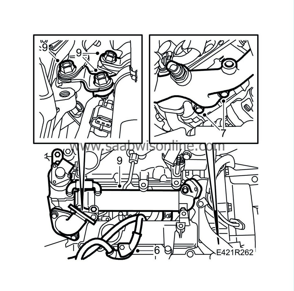
9.
|
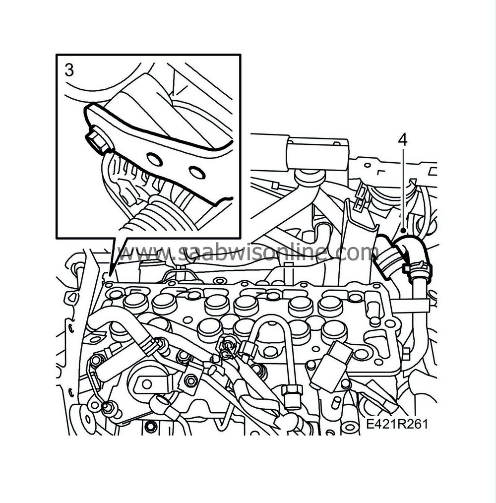
Fit the bolts securing the EGR valve with cooler pipe. Make sure that the hoses to the EGR valve are not bent.
Tightening torque: 21 Nm (15 lbf ft)
|
|
10.
|
Clean the sealing surfaces and make sure the holes are free from oil. Fit the rear and front camshaft holder frames using new gaskets. See illustration for fitting order.
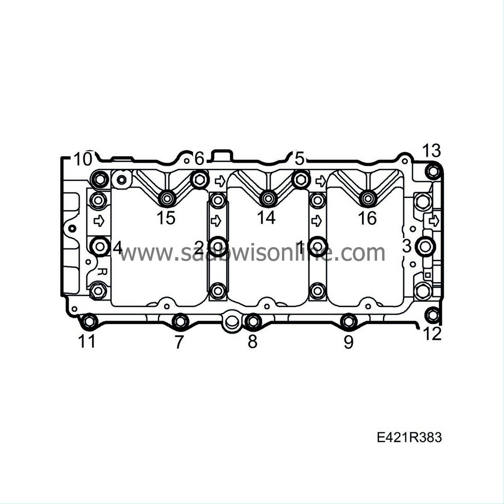
Tightening torque: M8 22 Nm (16 lbf ft)
Tightening torque: M6 12 Nm (9 lbf ft)
|
|
11.
|
Fit the hoses to the vacuum pump.
|
|
12.
|
Fit the studs securing the injector holders.
Tightening torque: Nm ( lbf ft)
|
|
13.
|
Fit the bolt in the cover at each timing belt gear and the bolt under the cover on the front cylinder bank.
|
|
14.
|
Fit the injectors using new seals as well as the fuel return pipes.
|
|
15.
|
Tighten the banjo connection in the rear of the camshaft holder frame.
|
|
16.
|
Fit the injector holders. Make sure the holder goes down in the injector slot. Tighten the nuts evenly.
Tightening torque, small nuts 5 Nm (4 lbf ft)
Tightening torque, large nuts 29 Nm (21 lbf ft)
|
|
17.
|
Fit the camshaft covers using new seals as described under
Replacing camshaft cover seals
. Apply a bead of silicon flange sealant, part no. 87 81 841, on the outer portion of the camshaft cover as illustrated.
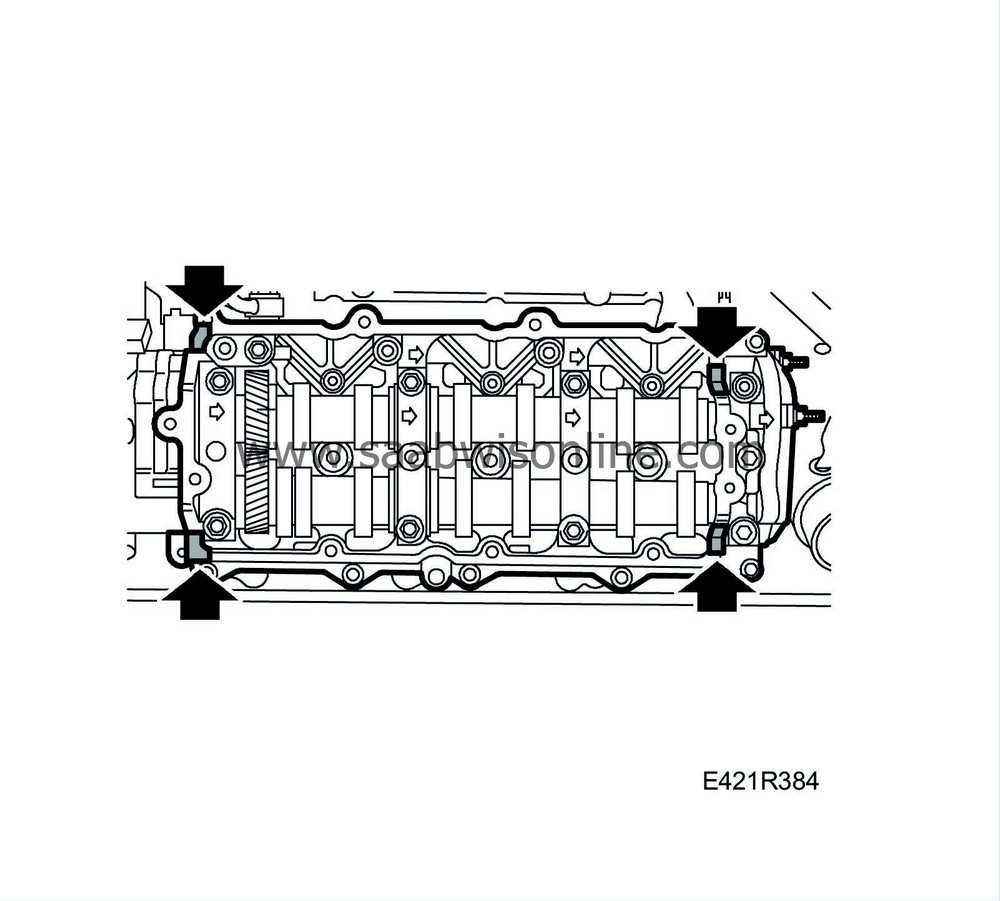
Tightening torque: 9 Nm (7 lbf ft)

|
|
18.
|
Fit the fuel feed pipe and the return fuel pipe. Fit the holders for the fuel pipe on the rear camshaft holder frame.
Tightening torque, fuel delivery pipe: 35 Nm (26 lbf ft)
|
|
19.
|
Fit the fuel return pipe against the rear and front cylinder banks.
|
|
20.
|
Fit the crankcase ventilation hoses.
|
|
21.
|
Fit the coolant pipe with bracket to the camshaft cover.
|
|
22.
|
Fit the exhaust pipe connecting the cylinder banks to each other as a unit. Use new gaskets and lubricate the bolts with Molycote 1000.
Tightening torque: 52 Nm (38 lbf ft)

|
|
23.
|
Fit the heat shields over the exhaust manifolds nearest the turbo pipes. Lower the jack slightly to position the rear heat shield.
|
|
24.
|
Fit the fuel pipe and fuel rail.
|
|
25.
|
Fit the turbo unit. Use a new gasket and apply Molycote 1000 to the threads.
Tightening torque: 21 Nm (15 lbf ft)

|
|
26.
|
Fit the oil and coolant pipes.
|
|
27.
|
Fit the diaphragm unit to the turbocharger and plug in the connector.
|
|
29.
|
Fit the control rod and lock it with the clip.
|
|
30.
|
Fit the turbo delivery pipe.
|
|
31.
|
Fit the turbocharger heat shield.

|
|
32.
|
Fit the upper intake manifold and the turbocharger's bracket.
Tightening torque: 21 Nm (15 lbf ft)
|
|
33.
|
Fit the cable rails and plug in the connectors.
|
|
34.
|
Fit the power steering pump with bracket.

|
|
35.
|
Fit the timing belt and idler pulley.
|
|
36.
|
Slowly and carefully relieve the pressure on the tensioner pulley. Fit the tensioner pulley.
|
|
37.
|
Check that the crankshaft pulley, camshaft pulleys and fuel pump pulley are aligned with the markings on the engine.
|
|
38.
|
Fit the timing belt cover.

|
|
39.
|
Fit the right-hand engine mounting with bracket and engine pad. Raise the engine slightly to insert the engine bracket bolts.
Tightening torque: 47 Nm (35 lbf ft)
|
|
40.
|
Lower the engine and remove the jack. Fit the nut to the right-hand engine mounting.
Tightening torque: 47 Nm (35 lbf ft)
|
|
41.
|
Fit the quick-release couplings on the fuel lines.
|
|
42.
|
Fit the nut of the rear engine pad.
Tightening torque: 47 Nm (35 lbf ft)
|
|
43.
|
Fit the lower bolt of the lifting eye.
|
|
44.
|
Move aside the lifting eye and fit the fan cowling.
|
|
45.
|
Fit the upper bolt securing the lifting eye and secure the dipstick pipe to the lifting eye.
|
|
46.
|
Plug in the fan connectors.
|
|
47.
|
Fit the catalytic converter without tightening the bolts.
|
|
48.
|
Fit the upper radiator hose.
|
|
49.
|
Fit the turbocharger heat shield.
|
Important
|
|
To reduce the risk of hoses mounted on the delivery side of the turbocharger coming loose due to low friction at high air pressure, the hoses and connecting pieces must be cleaned thoroughly before fitting. Use a rag dampened with 93 160 907 Motip Dupli cleaning agent to wipe clean inside the ends of the hoses. Clean the connecting pieces as well. If hose clips are rusty or damaged, they must be replaced so the correct clamping force is maintained.
|
|
|
|
|
50.
|
Fit the charge air hose and pipe to the upper intake manifold.
|
|
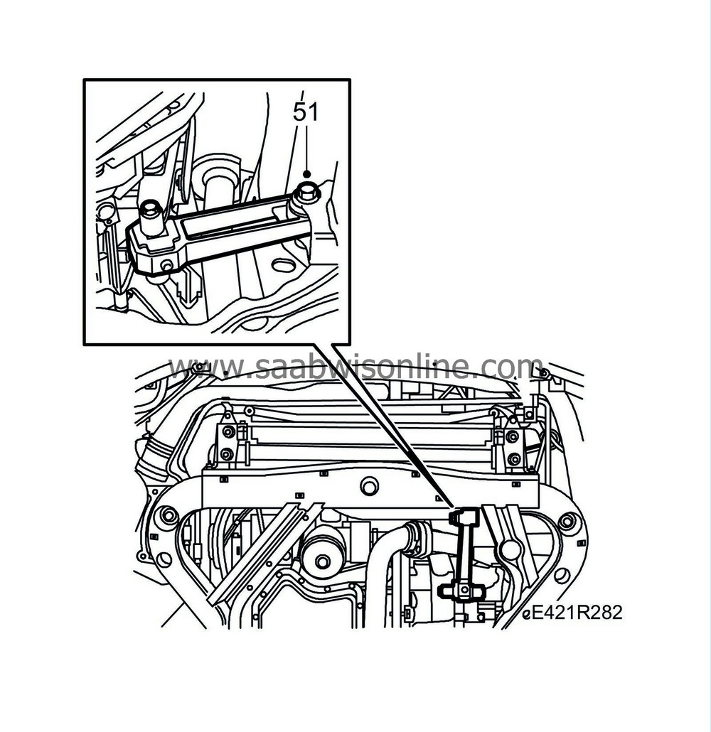
51.
|
Raise the car and fit the front bolt on the front torque arm.
Tightening torque: 90 Nm + 90° (66 lbf ft + 90°)
|
|
52.
|
Fit the bolts to the exhaust pipe bracket and the nuts on the exhaust pipe joint. Apply Molycote 1000 to the threads.

|
|
53.
|
Fit the charge air pipe to the charge air cooler.
|
|
54.
|
Raise the car and fit a new cable tie to the oil level sensor.
|
|
55.
|
Slowly and carefully relieve the tension on the belt tensioner and fit the multigroove V-belt. Tighten the lower bolt on the generator.
Tightening torque: 50 Nm (37 lbf ft)

|
|
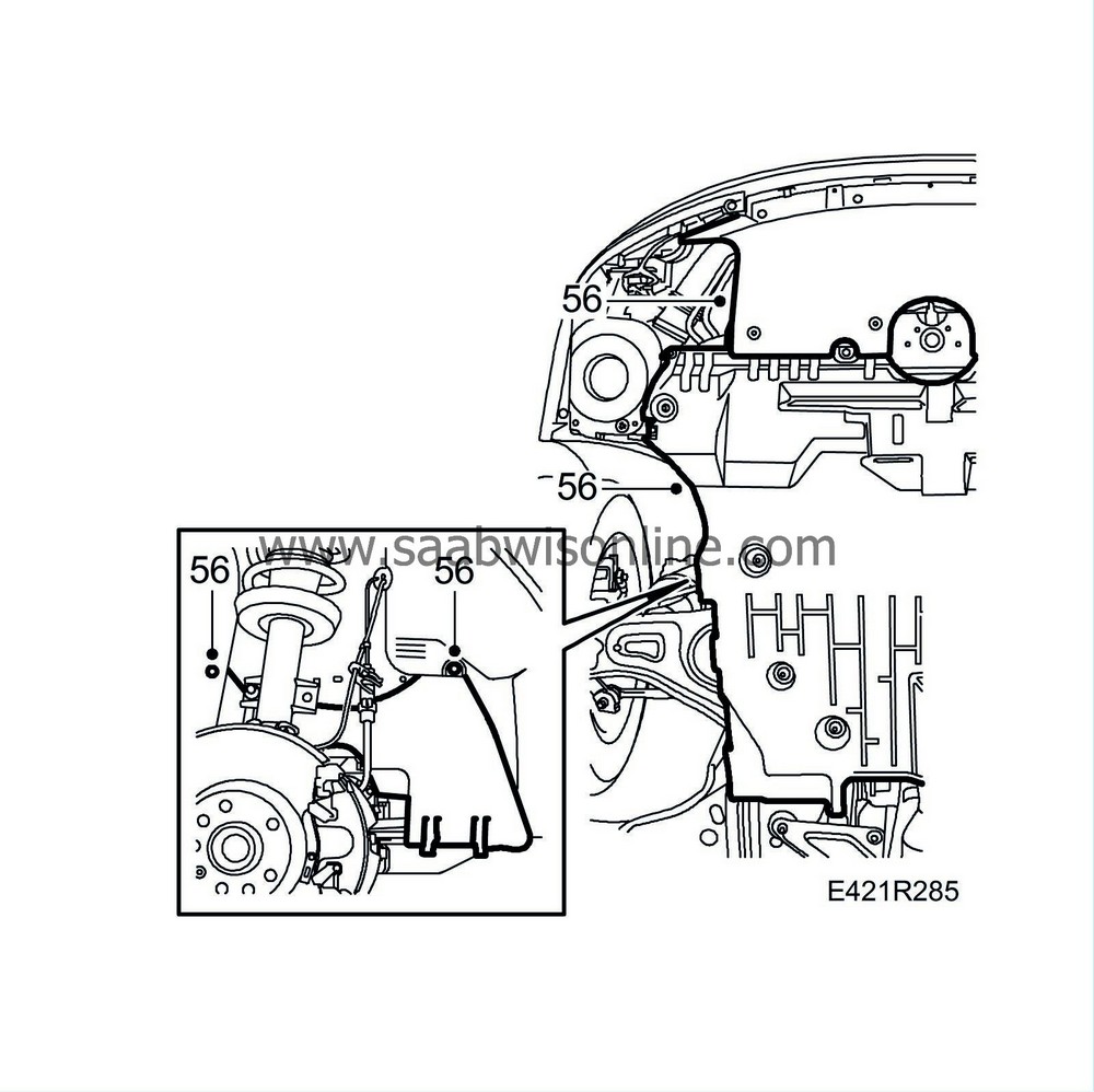
56.
|
Fit the lower engine cover and the front spoiler plate.
|
|
57.
|
Lower the car and tighten the catalytic converter bolts.
Tightening torque: 24 Nm (18 lbf ft)
|
|
58.
|
Fit the battery tray and the fuse holder.

|
|
59.
|
Fit the battery and the battery cover.
|
|
60.
|
Refit the upper engine cover.
|
|
61.
|
Fit the intake manifold with mass air flow sensor. Plug in the mass air flow sensor connector.
Tightening torque, mass air flow sensor: 3.5 Nm (2.5 lbf ft)
|


