Ignition discharge modules
|
|
Ignition discharge modules
|
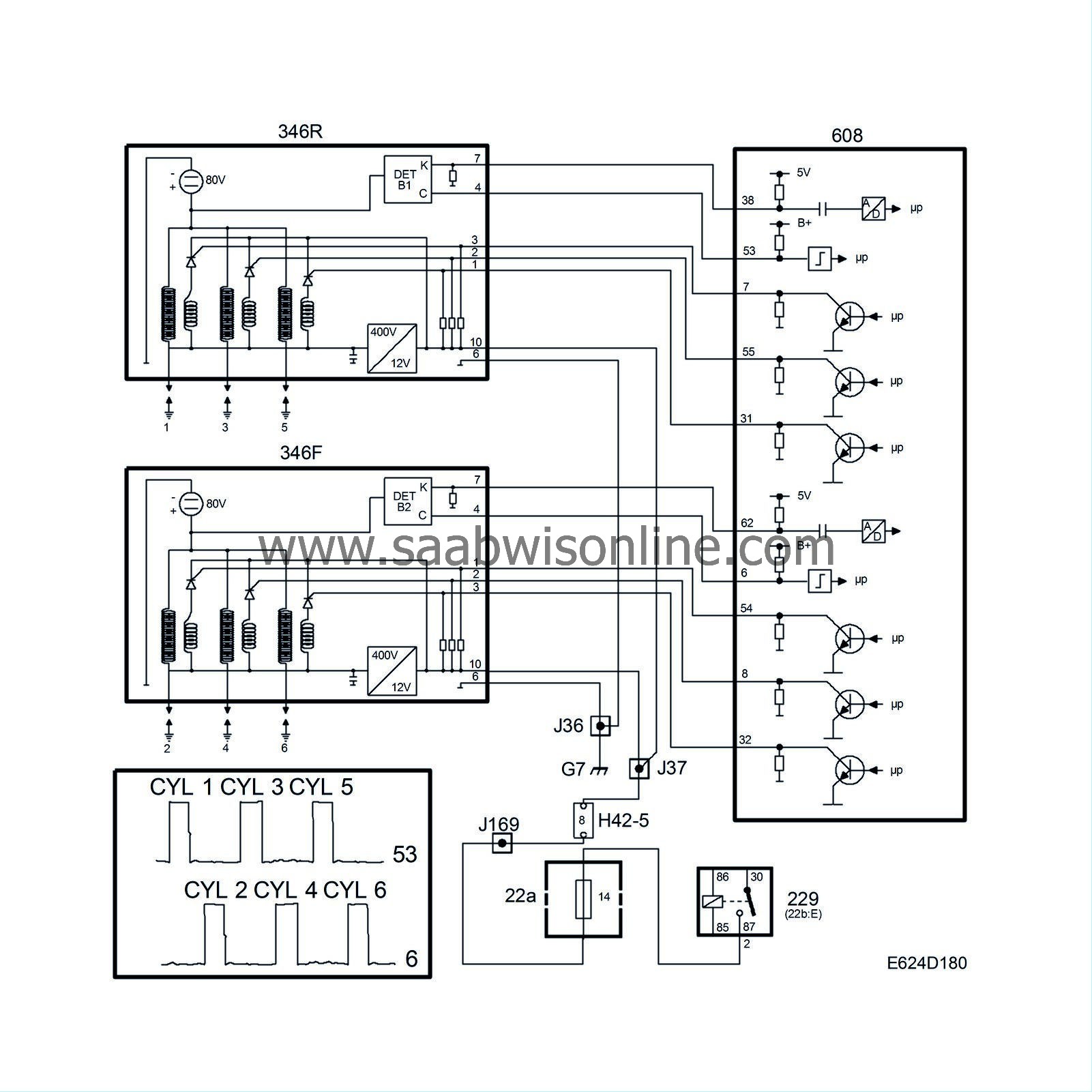
The two identical ignition discharge modules are mounted on the camshaft cover over the spark plugs. In each ignition discharge module there are 3 ignition coils whose secondary windings are connected directly to the spark plugs.
The ignition discharge modules are powered with B+ from the main relay and grounded to grounding point G7.
When the main relay is activated, B+ is supplied to the ignition discharge modules, which convert the 12V supply to 400V DC and store it in a capacitor. The 400V supply is connected to one pole of the primary windings of the 3 ignition coils.
There are 3 ignition leads running to each ignition discharge module from the control module as follows:
|
•
|
Cylinder 1 (Bank 1) from control module pin 7.
|
|
•
|
Cylinder 3 (Bank 1) from control module pin 55.
|
|
•
|
Cylinder 5 (Bank 1) from control module pin 31.
|
|
•
|
Cylinder 2 (Bank 2) from control module pin 54.
|
|
•
|
Cylinder 4 (Bank 2) from control module pin 8.
|
|
•
|
Cylinder 6 (Bank 2) from control module pin 32.
|
When the control module grounds pin 7, the other pole of the primary winding of the ignition coil for cylinder 1 is connected to the B+ input on the ignition discharge module. The 400V supply is stepped up to a maximum of 40kV in the ignition coil for cylinder 1. Ignition for all cylinders is performed in the same way.
|
•
|
If an open circuit should occur in the power supply to the ignition discharge module, the voltage on all ignition leads will be 0V and then trouble code P1310 (Bank 1) or P1320 (Bank 2) will be generated.
|
|
•
|
If a break occurs in an individual trigger lead, no diagnostic trouble code will be generated.
|
System reaction to a fault
Fuel shut-off to all cylinders, even if only one of the discharge modules loses its power.
|
Combustion signals, synchronization
|
The Trionic T7 has no camshaft position sensor as normally required for sequential knock control and fuel injection.
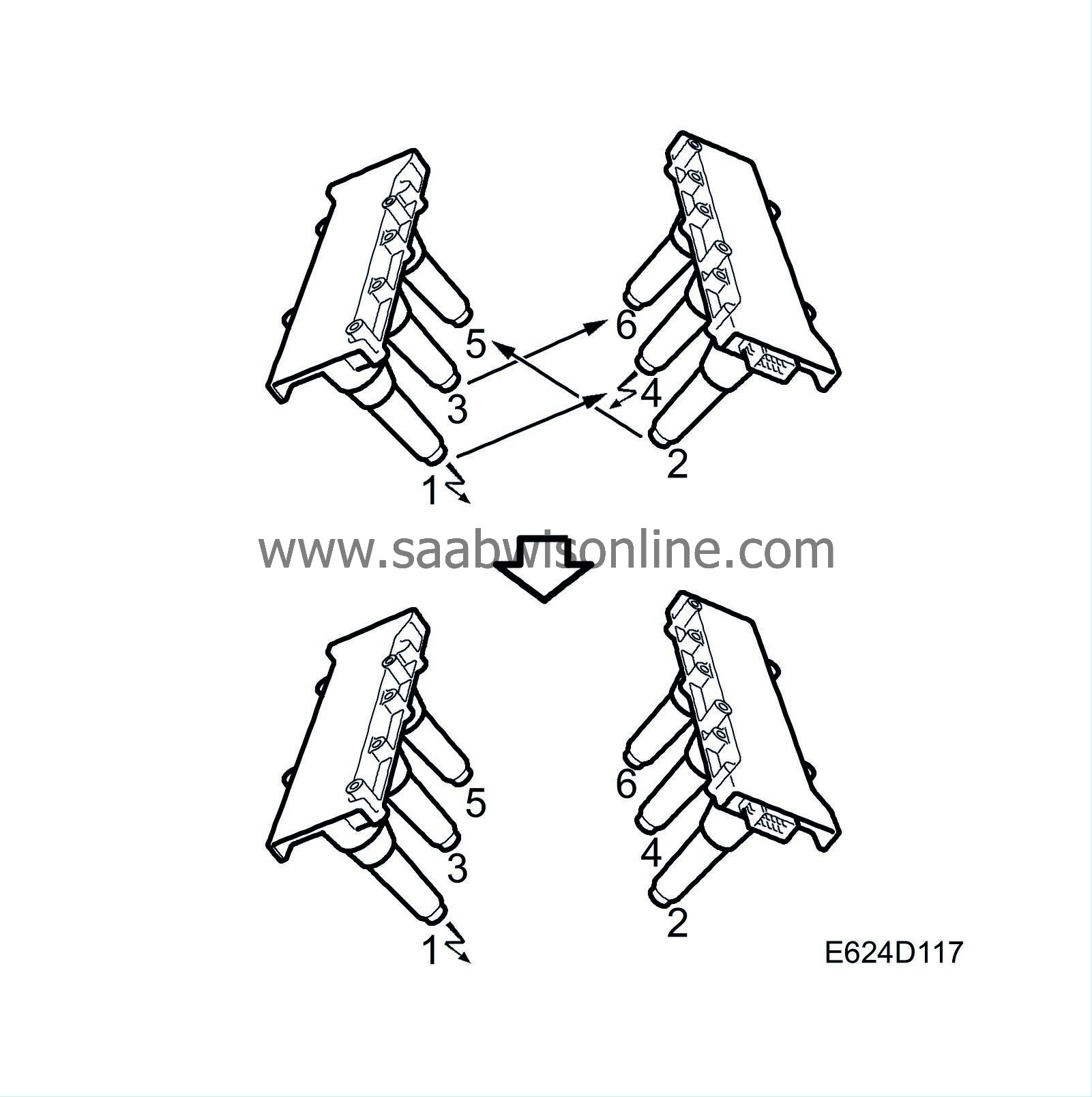
As the firing order of the engine is 1-2-3-4-5-6 while cylinders 1-3-5 are in bank 1 and cylinders 2-4-6 in bank 2, combustion will take place alternately in the two banks.
On starting, the control module does not know which of cylinder 1 and 4 is in the compression position, so ignition takes place in both cylinder 1 and cylinder 4 simultaneously. Ignition takes place in cylinders 2 and 5, and 3 and 6 respectively in the same way.
The control module determines whether combustion is taking place in bank 1 or bank 2 in the following way:
One pole of the secondary windings of the 3 ignition coils is normally connected to the relevant spark plug. The other pole is not grounded direct but connected to 80 V. This means that a voltage of 80 V is always present across the spark plug gap except just as the spark is produced.
When combustion takes place, the temperature in the combustion chamber is very high. The gases are ionized and begin to conduct current. This means that current passes between the spark plug electrodes without producing a spark.
As the circuit is completed between the spark plug electrodes, the current (80 V) flowing across the gap drops sharply. The voltage drop will be proportional to the pressure and temperature in the combustion chamber.
A detector measures the voltage drop over the three spark electrodes in each discharge module. If combustion is taking place in cylinders 1-3-5 (bank 1), the discharge module sends a B+ pulse to control module pin 53. In the same way, the discharge module for bank 2 sends a B+ pulse to control module pin 6 if combustion is taking place in cylinders 2-4-6.
If cylinders No. 1 and No. 4 are triggered and a B+ pulse is received on control module pin 53 at the same time, the control module knows that cylinder No. 1 has fired.
As soon as combustion signals are received on control module pins 53 and 6, both ignition and fuel injection are synchronized to the engine firing order.
Combustion signals
If there is an open circuit on both leads to control module pins 53 and 6, the ignition and injection will not be synchronized. Knock detection will then take place in parallel on cylinders 1+4 and cylinders 2+3.
|
•
|
If there is an open circuit to control module pin 53, diagnostic trouble code P1312 will be generated.
|
|
•
|
If there is an open circuit to control module pin 6, diagnostic trouble code P1334 will be generated.
|
|
•
|
If the firing cannot be synchronized with the camshaft, diagnostic trouble code P0340 will be generated.
|
System reaction to a fault
|
•
|
If an open circuit occurs on any of the leads to control module pins 53 and 6, the firing and fuel injection will not be synchronized. Knock detection will then take place in parallel on cylinders 1+4, cylinders 2+5 and cylinders 3+6.
|
|
Note
|
Note
|
|
•
|
If there is a short circuit on any of the two combustion signals to ground, synchronization will not be performed and there will be no diagnostic trouble codes generated for the specific fault. A diagnostic code for misfiring will be generated instead.
|
Misfiring
|
•
|
Emission-related misfiring will generate diagnostic trouble code P0300-P0304.
|
|
•
|
If catalyst damaging misfiring occurs, diagnostic trouble code P1300-P1304 will be generated. CHECK ENGINE will flash during the misfiring.
|
|
•
|
If catalyst damaging misfiring occurs in conjunction with a fuel level below 4 litres, diagnostic trouble code P1390-P1394 will be generated. CHECK ENGINE will flash during the misfiring.
|
System reaction to a fault
|
•
|
Closed loop is blocked at high engine loads.
|


