To remove, gearbox, V6 diesel
|
|
To remove, gearbox, V6 diesel
|
|
Important
|
|
Cables, hoses, leads etc. are secured with hard plastic cable ties. After being tightened, the ends are cut off, leaving sharp edges at the fixing points. Be aware of the risk of injury due to these sharp ends of cable tie.
|
|
|
|
1.
|
Place the car on a lift.
|
|
3.
|
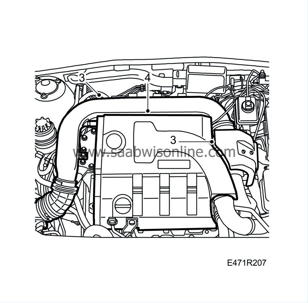
Remove the turbocharger heat shield and the intake manifold.
|
|
4.
|
Remove the upper engine cover.
|
|
5.
|
Remove the plastic battery cover.
|
|
6.
|
Disconnect the battery cables from the battery and remove the battery.
|
|
7.
|
Remove the battery tray.
|
|
8.
|
Raise the car and remove the wheels.
|
|
9.
|
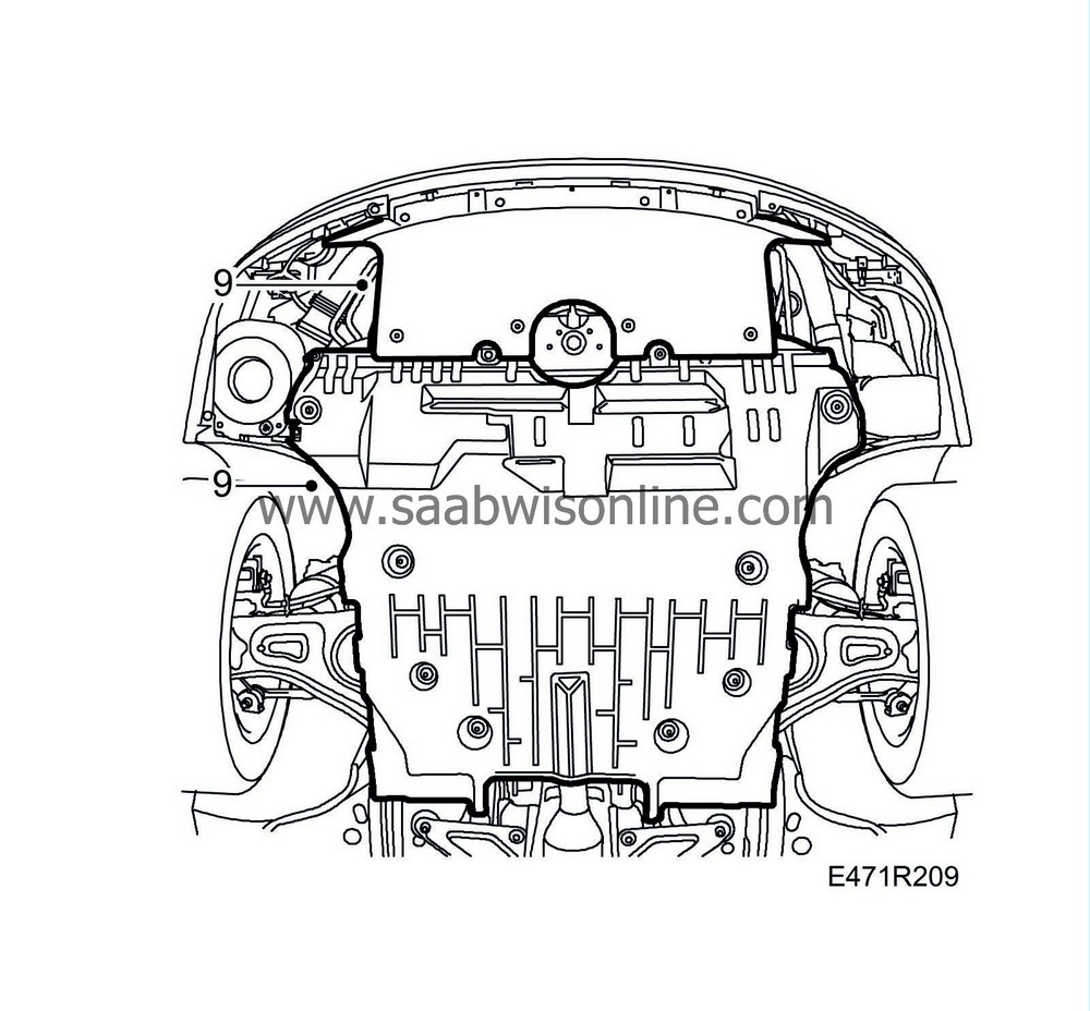
Remove the two lower engine covers.
|
|
10.
|
Disconnect the level sensor for the Xenon headlamps from the bracket and move it aside (option).
|
|
11.
|
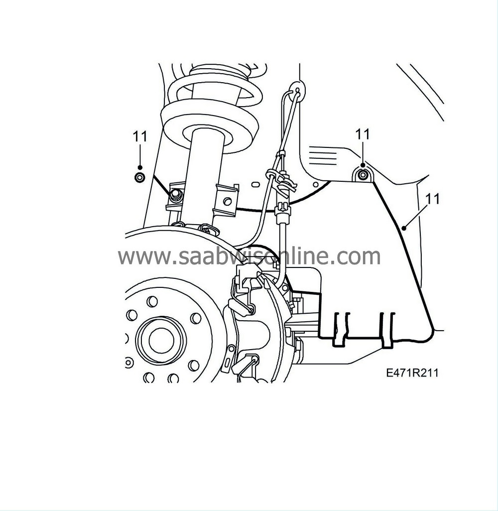
Remove the side covers from both wheel housings.
|
|
12.
|
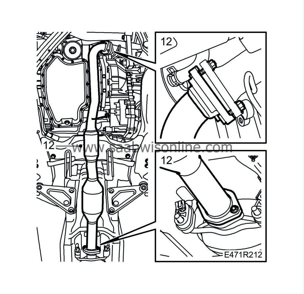
Remove the centre section of the exhaust pipe.
|
|
13.
|
Remove the bolts securing the front exhaust pipe to the gearbox bracket.
|
|
14.
|
Lower the car and remove the hose from the intake manifold.
|
|
15.
|
Disconnect the front exhaust pipe from the turbocharger and pull up the front exhaust pipe and catalytic converter.
|
|
16.
|
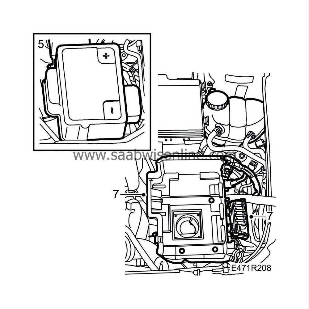
Remove the relay box and place it to one side.
|
|
17.
|
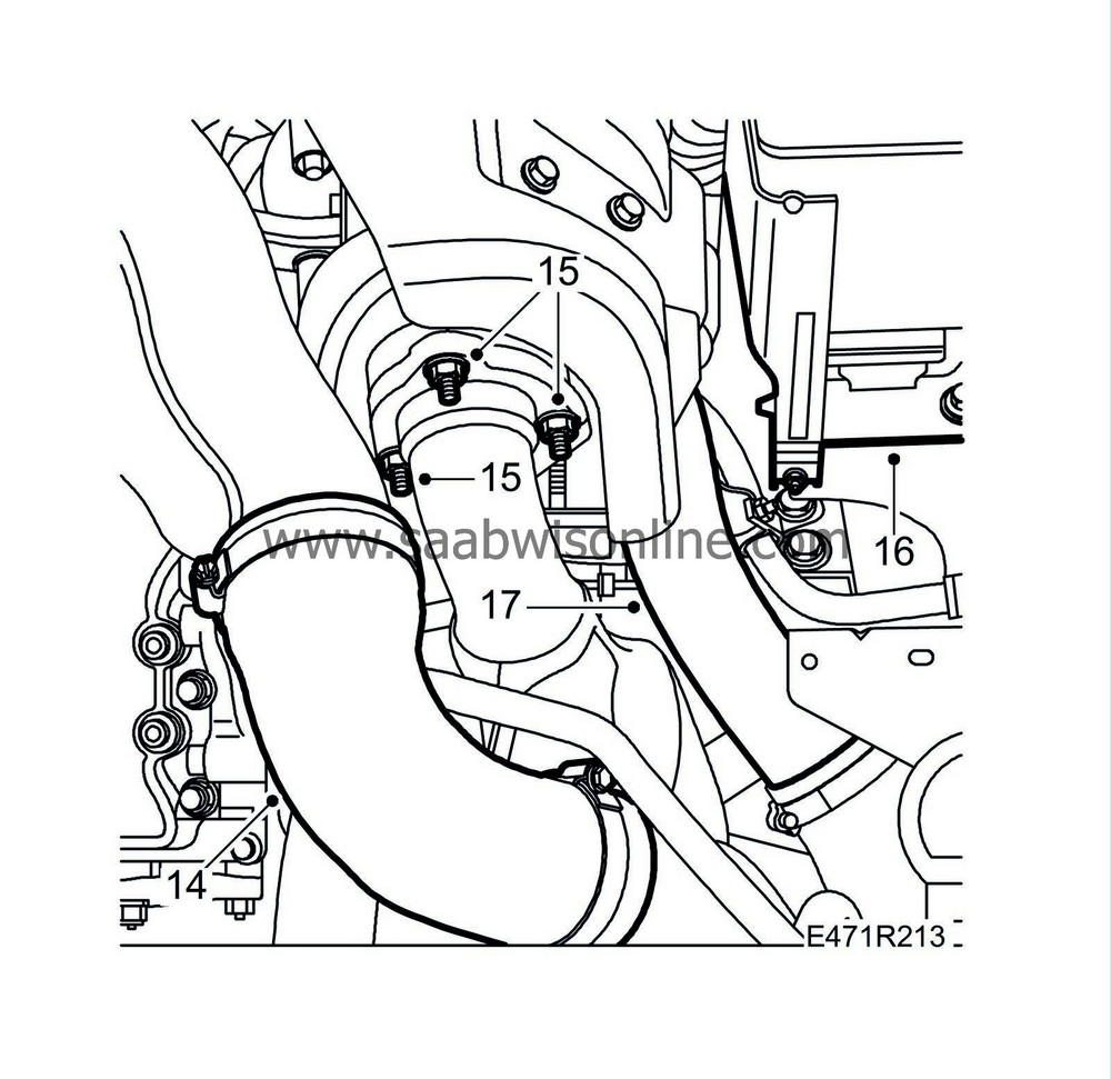
Remove the pipe between the turbocharger and charge air cooler.
|
|
18.
|
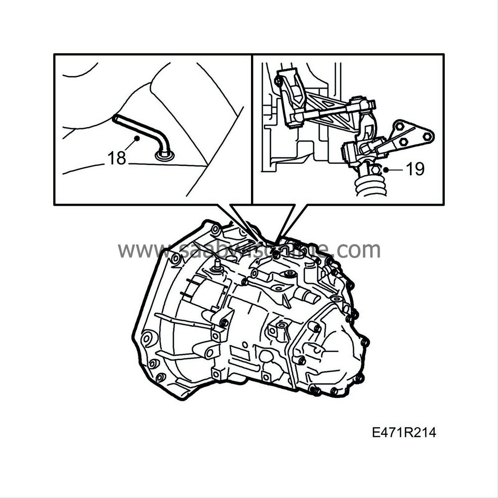
Engage 4th gear and remove the plastic plug from the gearbox. Lock 4th gear in the gearbox by inserting
87 92 335 Locking pin.
|
|
19.
|
Remove the clip from above that secures the selector rod in the linkage on the gearbox.
|
|
20.
|
Lift up the gaiter. Engage 3rd gear so that the selector rod disengages from the linkage and insert locking pin 87 92 335 into the gear lever housing.
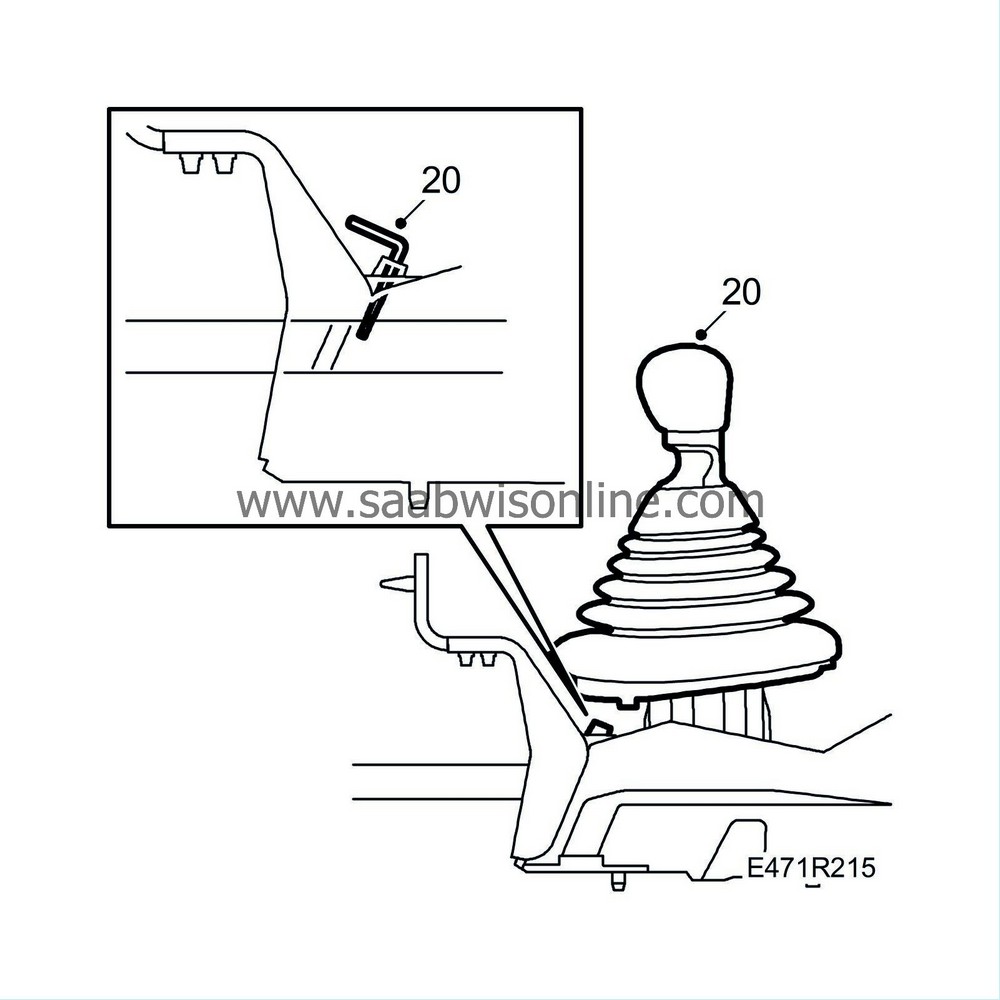
|
|
21.
|
Prevent brake fluid from escaping from the brake fluid reservoir by clamping the brake fluid hose with
30 07 739 Pinch-off pliers
.
|
|
22.
|
Remove the clip by the slave cylinder and disconnect the connection for the delivery line. Refit the clip.
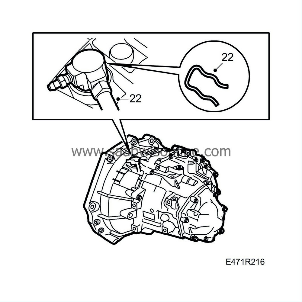
|
|
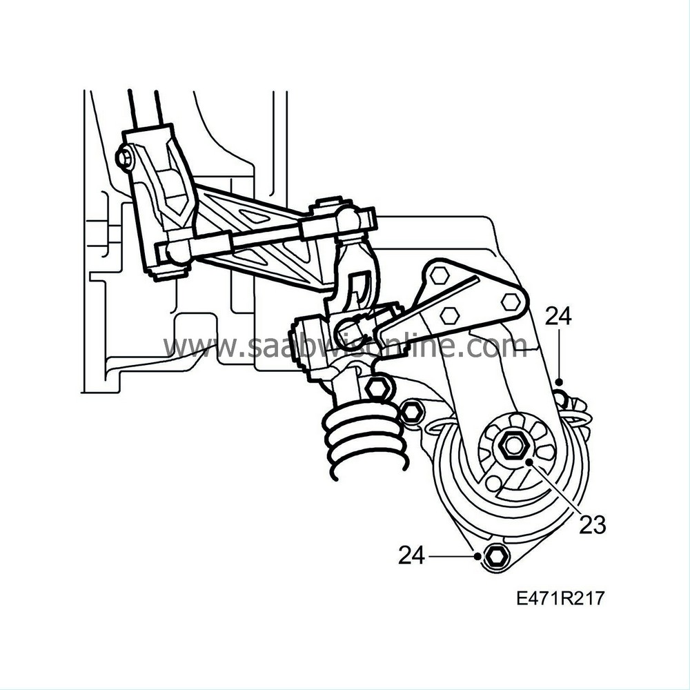
23.
|
Remove the nut from the rear engine mounting.
|
|
24.
|
Undo the bolts securing the engine pad. Use a long 10 mm socket, two extensions with ball (e.g. 30 17 613) and
Extension 3/8" 500 mm
82 93 102. Leave the bolts in place.
|
|
26.
|
Remove the nut and bolts securing the left-hand engine pad and lift out the pad.
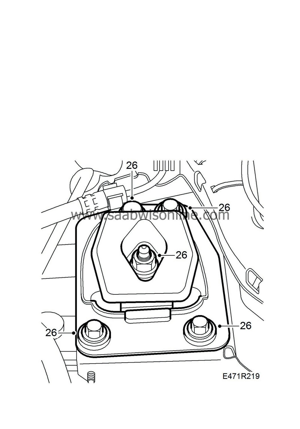
|
|
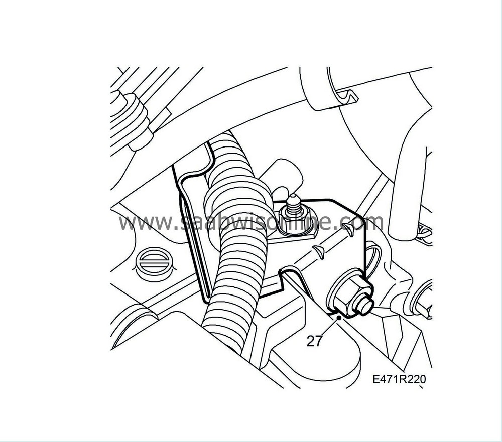
27.
|
Remove the bolt securing the cable duct to the gearbox.
|
|
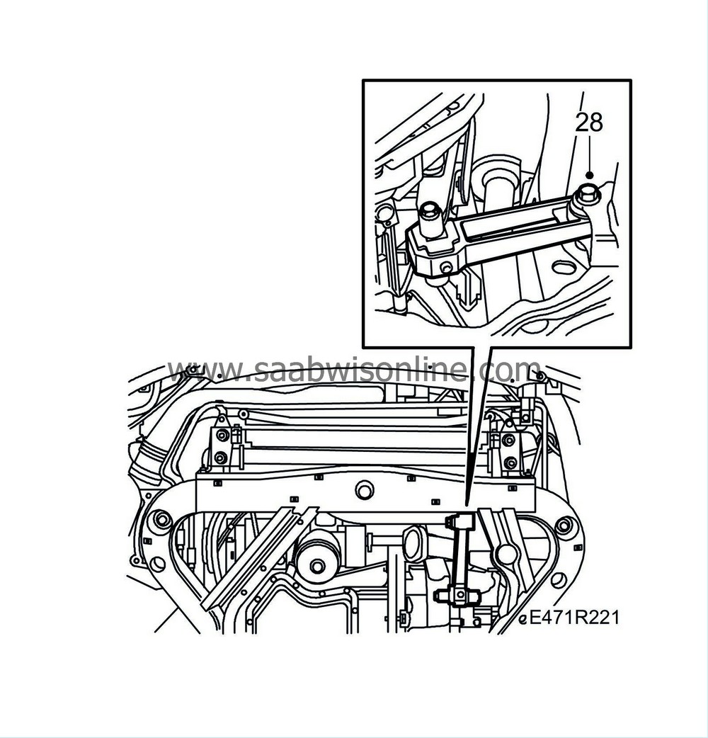
28.
|
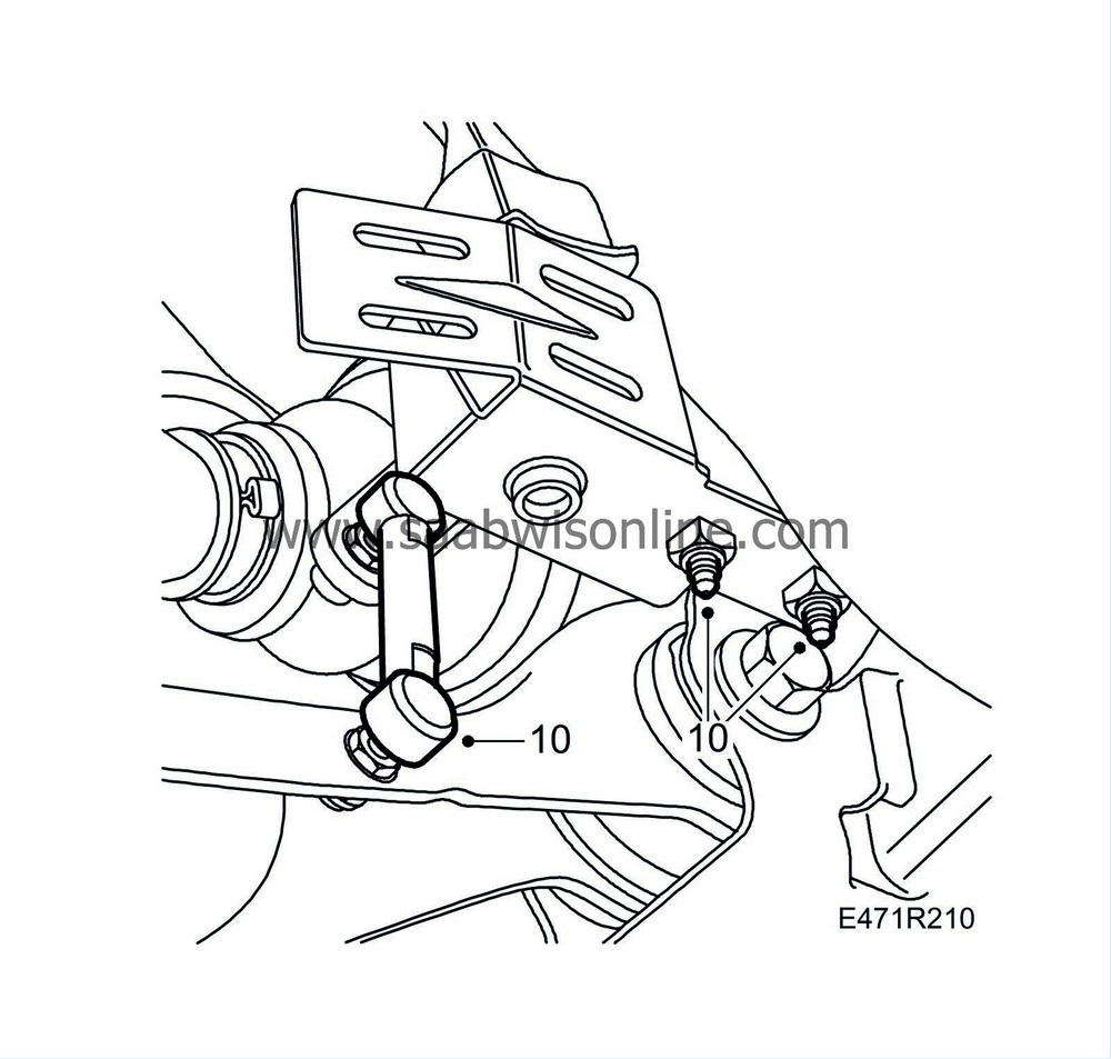
Raise the car and remove the charge air pipe nut and the bolt that secures the front torque arm to the subframe.
|
|
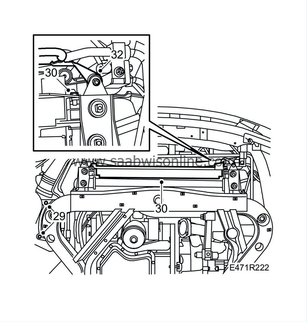
29.
|
Remove the air cleaner from the subframe.
|
|
30.
|
Remove the lower air baffle from the radiator.
|
|
31.
|
Place a
83 95 212 Strap
around the radiator and radiator crossmember to suspend the radiator.
|
|
32.
|
Remove the rubber mountings for the steering servo cooler pipe.
|
|
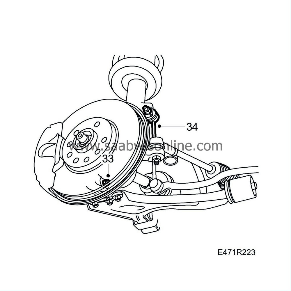
33.
|
Remove the bolts that secure the outer ball joints to the steering swivel member on both sides.
|
|
34.
|
Detach the upper anti-roll bar ball joints. Use a 17 mm spanner to prevent the boot from twisting. If the spanner is too wide to fit between the boot and the suspension strut, it must be ground narrower.
|
|
35.
|
Remove the bolts securing the rear support plates and the rear bolts for the subframe.
|
|
36.
|
Split the pipe for the battery cooling.
|
|
37.
|
Position the lifting trolley under the subframe. Trolley 83 95 311,
parent fixture
83 94 801, adjusting feet 83 95 170, basic fixture 83 95 188 and assembly fixture 83 95 196.
|
|
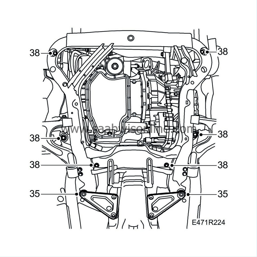
38.
|
Remove the remaining bolts securing the subframe.
|
Note
|
|
Do not mix up the centre bolts on the subframe with the other bolts when fitting (different sizes and designs).
|
|
|
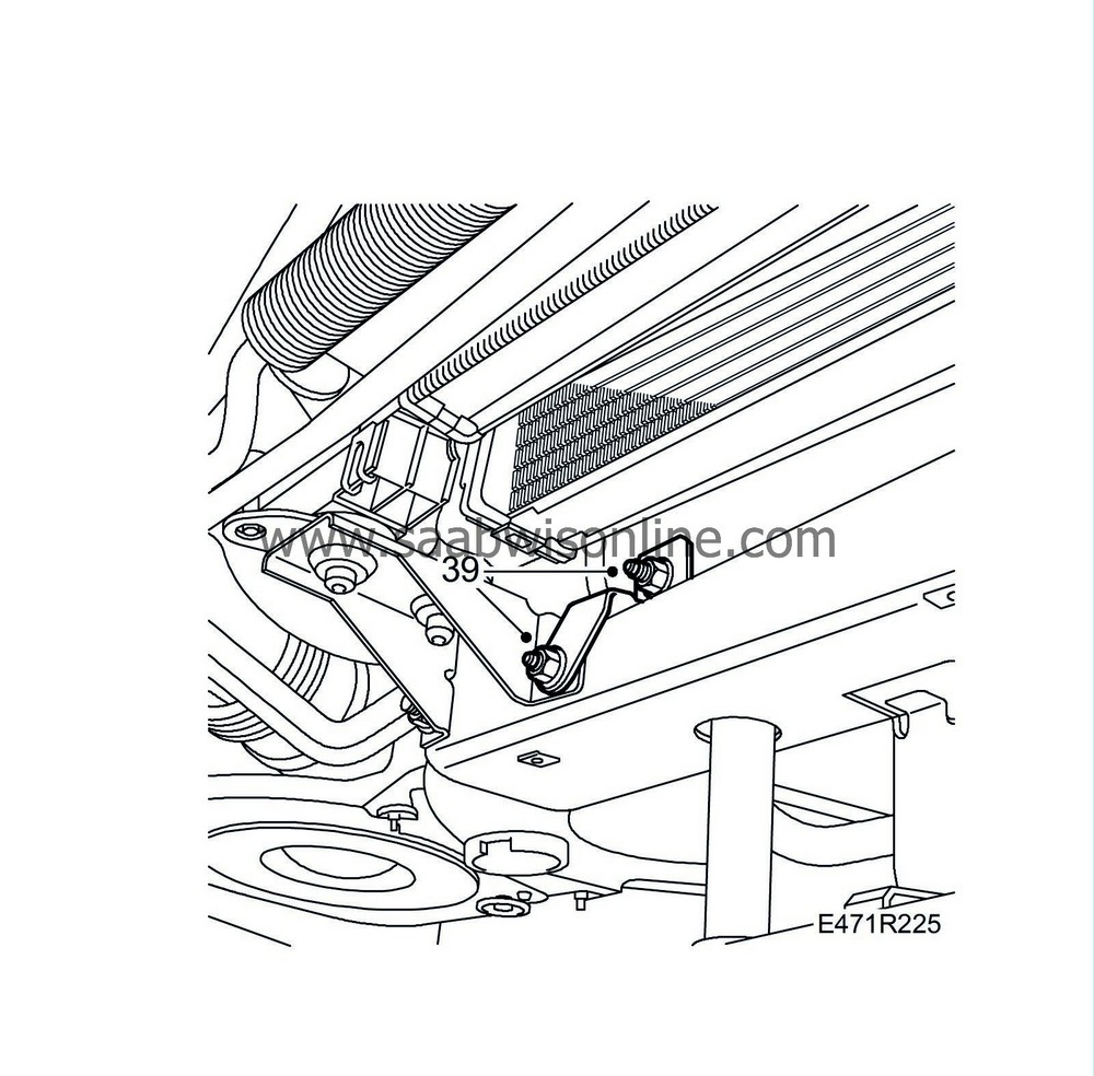
39.
|
Remove the bracket for the charge air cooler pipe.
|
|
40.
|
Lower the subframe until you can access the steering gear bolts. Remove the bolts.
|
|
41.
|
At the same time, open the clamps securing the steering servo pipe and secure the coolant pipe for the steering servo with a cable tie. Disconnect the A/C pipe from its clips.
|
|
42.
|
Move the trolley with subframe to one side.
|
|
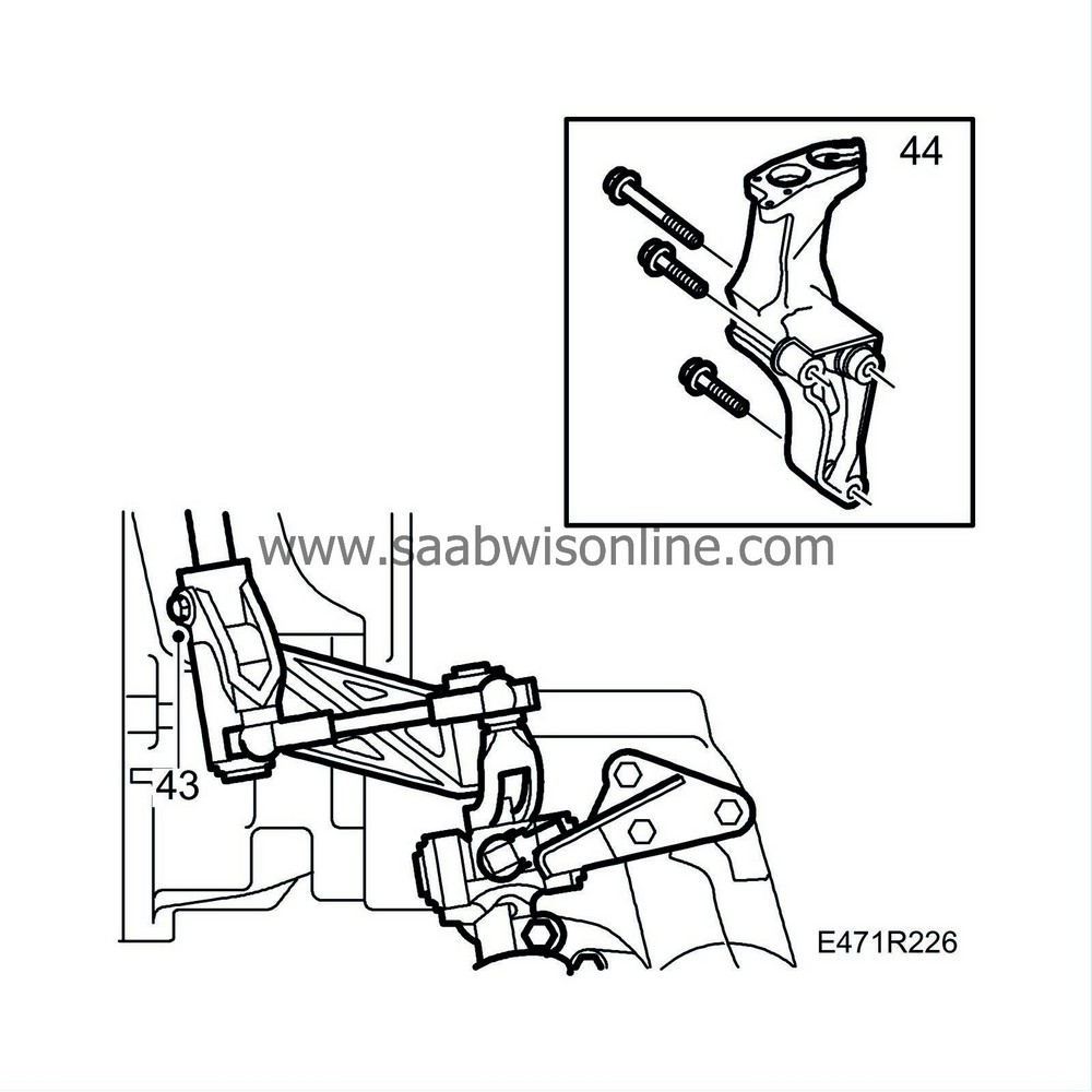
43.
|
Remove the bolt securing the gear linkage to the selector rod.
|
|
44.
|
Remove the rear engine mounting and the engine pad. The gear linkage will follow.
|
|
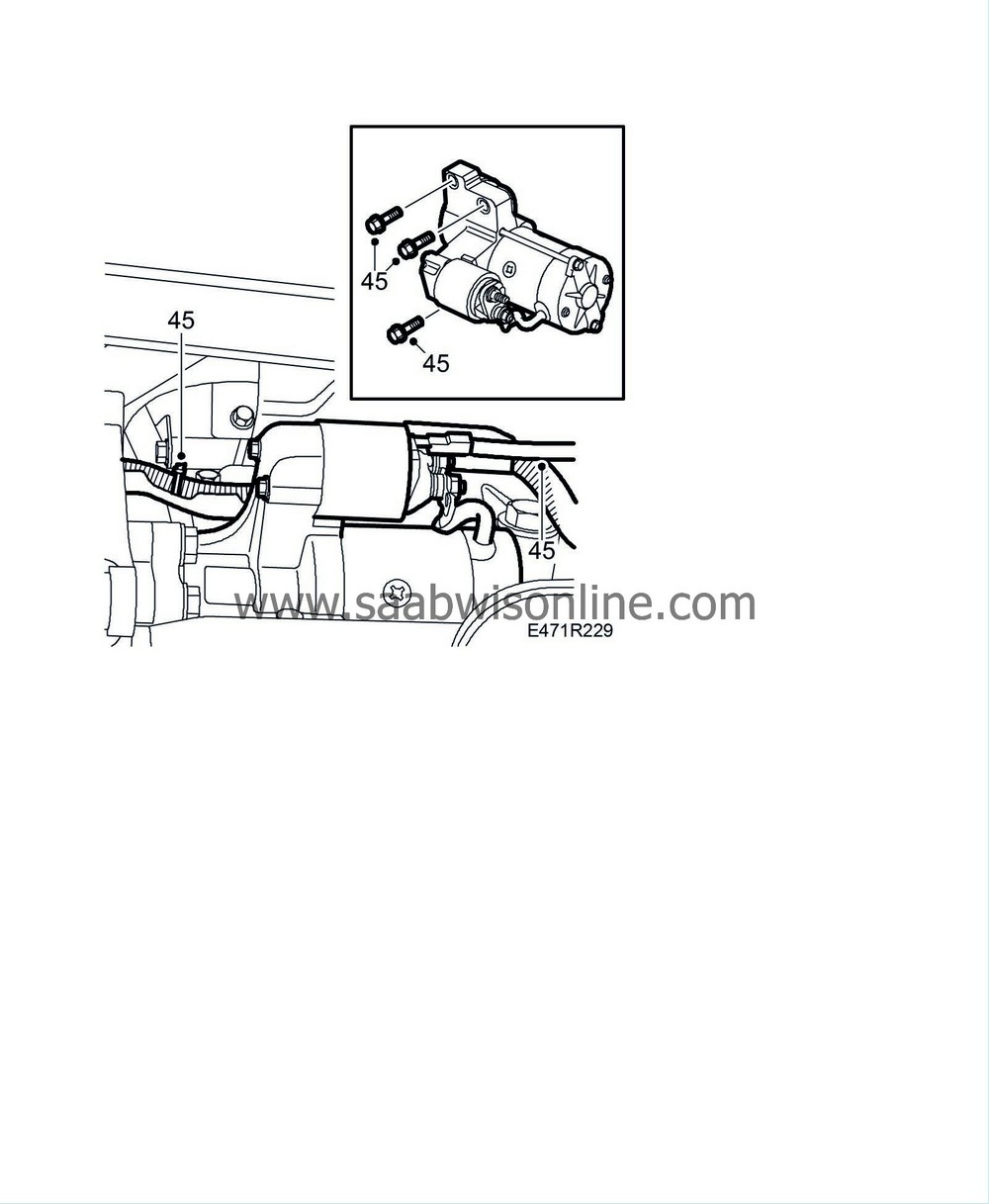
45.
|
Unplug the connectors and remove the starter motor.
|
|
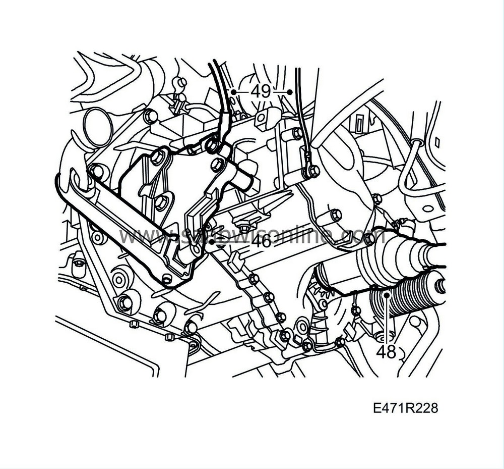
46.
|
Remove the torque arm bracket from the gearbox. (Only if the gearbox is to be changed or dismantled.)
|
|
47.
|
Drain the gearbox oil.
|
|
49.
|
Disconnect the ground cables from the gearbox and lower the car.
|
|
50.
|
Lower the unit so that the gearbox goes clear from the structural member.
|
|
51.
|
Remove the upper gearbox bracket from the gearbox.
|
|
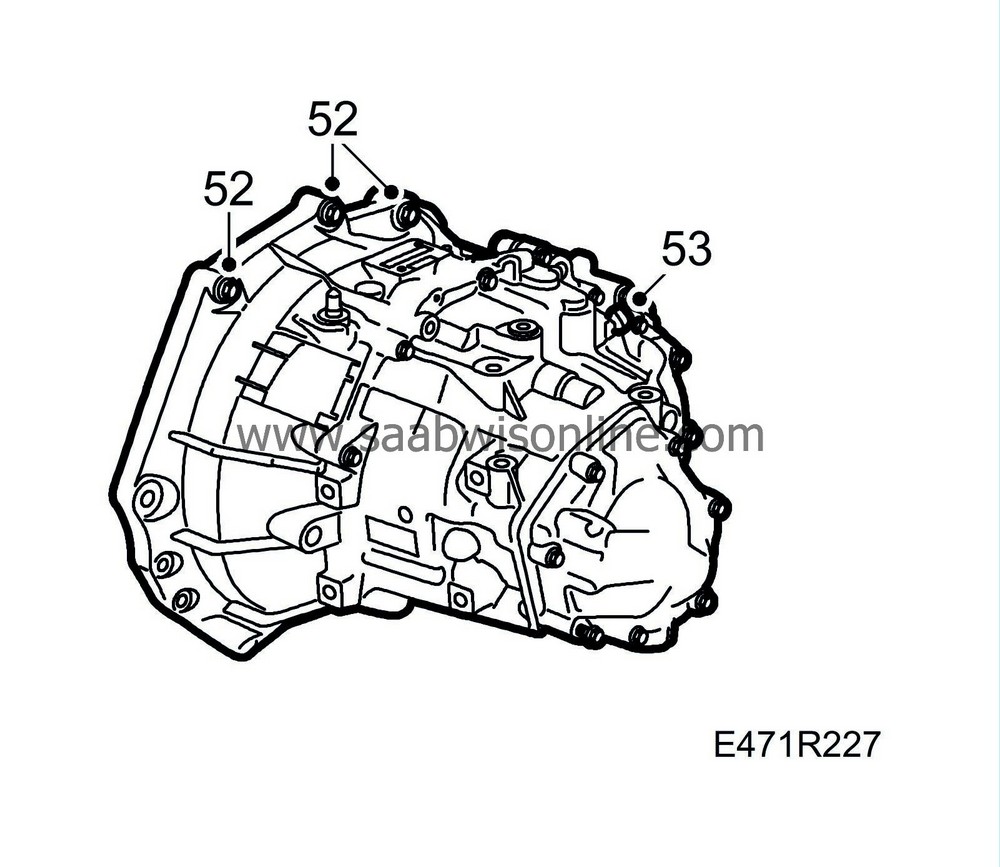
52.
|
Remove the upper bolts securing the gearbox to the engine.
|
|
53.
|
Unplug the reversing light switch.
|
|
55.
|
Connect the lifting tool to the gearbox. Use bolts that are approximately 20 mm longer than the gearbox bolts. Adjust the lifting tool so that it is centred with the centre and mating face of the gearbox.
|
|
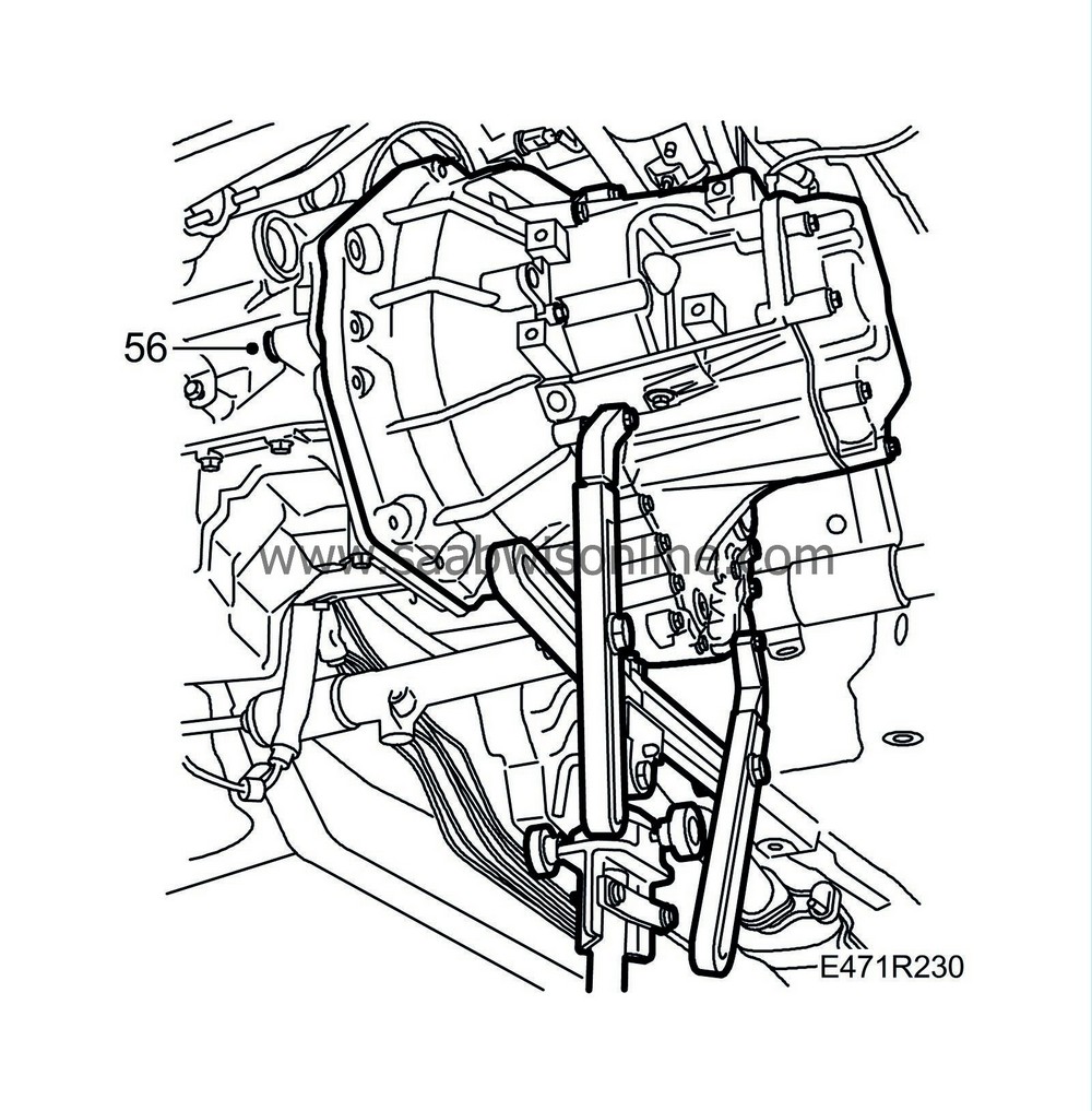
56.
|
Remove the lower bolts securing the gearbox to the engine.
|
|
57.
|
Pull out and lower the gearbox.
 Warning
|
|
Take care not to tip the jack.
|
|
|
|
|
|
|
|
58.
|
Lift the gearbox from the jack and remove the lifting tool from the gearbox.
|


