TCS modulation with braking
|
|
TCS modulation with braking
|
|
1.
|
Pressure Increase Valve 1
|
|
2.
|
Pressure Increase Valve 2
|
|
3.
|
Pressure Relief Valve 1
|
|
4.
|
Pressure Relief Valve 2
|
|
10.
|
Inlet valve, FL (ABS)
|
|
11.
|
Inlet valve, FR (ABS)
|
|
12.
|
Inlet valve, RL (ABS)
|
|
13.
|
Inlet valve, RR (ABS)
|
|
14.
|
Outlet valve, FL (ABS)
|
|
15.
|
Outlet valve, FR (ABS)
|
|
16.
|
Outlet valve, RL (ABS)
|
|
17.
|
Outlet valve, RR (ABS)
|
Since TCS modulation braking occurs without depression of the brake pedal, the hydraulic unit must build up and modulate the pressure to the driven wheel which is to be braked if it develops wheelspin in excess of the permitted limit.
The TC/ABS control module activates TCS modulation with braking when the following criteria are met:
|
•
|
One of the driven wheels is spinning more than the permissible limit.
|
|
•
|
The driver does not depress the brake pedal, the brake lights switch input is not active.
|
|
•
|
Road speed is below 100 km/h.
|
When TCS modulation with braking occurs, the vacuum servo, primary piston and secondary piston are in their rest positions. In the valve block the inlet and outlet valves are in their rest positions, that is to say the inlet valves are open and the outlet valves are closed.
The TC/ABS control module starts the return pump while the pressure relief valve is closed to allow the pressure to build up. This is achieved by opening the pressure increase valve to supply bake fluid to the return pump. The control module closes the pressure increase valve at a predetermined pressure. The pressure is then modulated as the control module opens the pressure increase valve to increase the pressure, keeps the pressure increase and pressure relief valves closed (to retain pressure) and opens the pressure relief valve to reduce the pressure. The excess brake fluid resulting from opening the pressure relief valve is returned to the master cylinder.
When TCS modulation starts, a “filling pulse" is generated, which means that a small (same for both wheels) amount of pressure is built up in the wheel cylinders of both driven wheels, irrespective of which wheel is to be modulated with braking. Pressure will be maintained on the front wheel which is not to be braked, i.e. both the pressure increase and pressure relief valves will be closed. This is in order to prepare for an application of the brakes if it should prove necessary.
The pressure increase valve on the wheel which is spinning will open. This causes an increase in the pressure to the wheel cylinder and the wheel is braked.
Modulation continues until:
|
•
|
The friction between wheels and road surface changes so that wheelspin does not exceed the limit.
|
|
•
|
The driver brakes (brake lights switch input active).
|
|
•
|
Modulation is interrupted by the TC/ABS control module due to the risk of overheating the brakes.
|
When modulation is interrupted, the TC/ABS control module stops the return pump, closes the pressure increase valve and opens the pressure relief valve, i.e. the valves and the return pump will return to their rest positions.
If TCS modulation is interrupted by the driver braking, TCS modulation with braking will be disengaged and the braking function will be chosen instead. Any delay that may then arise will not affect the braking function since the brake fluid can flow through the check valve which is mounted parallel with the pressure relief valve.
Interruption of TCS modulation with braking due to the danger of overheating the brakes occurs as a result of the TC/ABS control module continuously recording the aggregate duration of TCS modulation with braking over a certain period of time.
The time is compared with a preprogrammed maximum value and modulation with braking is disengaged when this is exceeded.
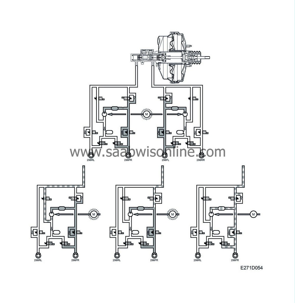
Phase 1 Pressure build-up on both front wheels (filling pulse)
The return pump starts, the pressure increase valve opens (fixed time), the pressure relief valve closes.
Phase 2 Pressure increase in the circuit with wheelspin.
Pressure increase valve open, pressure relief valve closed, return pump running.
Phase 3 Pressure reduction in the circuit with wheelspin.
Pressure relief valve open, pressure increase valve closed, return pump running.
Phase 4 Release
Braking function selected. Pressure increase valve closes, pressure relief valve opens, both valves return to rest position, return pump stops.


