Diesel pump with control module, 4-cyl (595)
|
|
Diesel pump with control module, 4-cyl (595)
|
 Warning
|
|
Removal of the fuel pump involves partial dismantling of the car's fuel system. The following points must therefore be observed in connection with this work:
|
|
|
|
|
|
|
•
|
Work only in a well-ventilated area. If approved equipment for the extraction of fuel vapours is available, be sure to use it.
|
|
•
|
Wear suitable gloves. Prolonged contact with fuel can cause skin irritation or dermatitis.
|
|
•
|
Keep a class BE fire extinguisher near at hand. Be mindful of the danger of sparks caused by short circuits and when connecting and disconnecting leads in electrical circuits.
|
|
•
|
No smoking anywhere in the vicinity,
|
|
Important
|
|
Be particulary observant regardning cleanliness when working on the fuel system. Loss of function may occur due to very small particles. Prevent dirt and grime from entering the fuel system by cleaning the connections and plugging pipes and lines during disassembly. Use 82 92 948 Plugs, A/C system assembly. Keep components free from contaminants during storage.
|
|
|
|
2.
|
Remove the right-hand front wheel.
|
|
3.
|
Remove the lower engine cover.
|
|
4.
|
Remove the drive belt cover.
|
|
5.
|
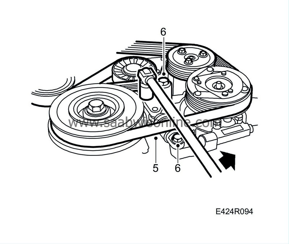
Mark the direction of rotation, take the tension off the multigroove belt and remove the belt.
|
|
6.
|
Remove the belt tensioner.
|
|
7.
|
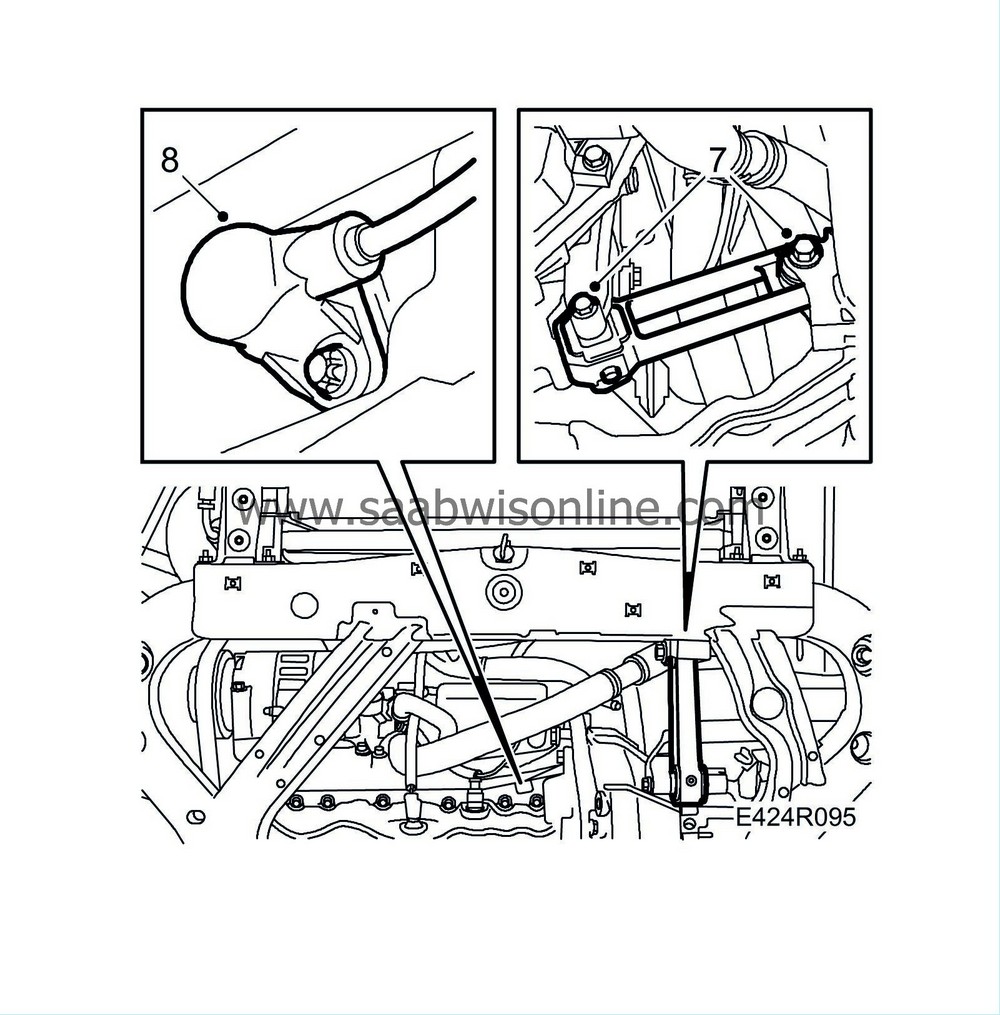
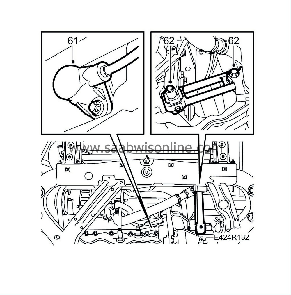
Remove the front bolt on the torque arm and undo the rear one. Secure the torque arm with a cable tie if necessary.
|
|
8.
|
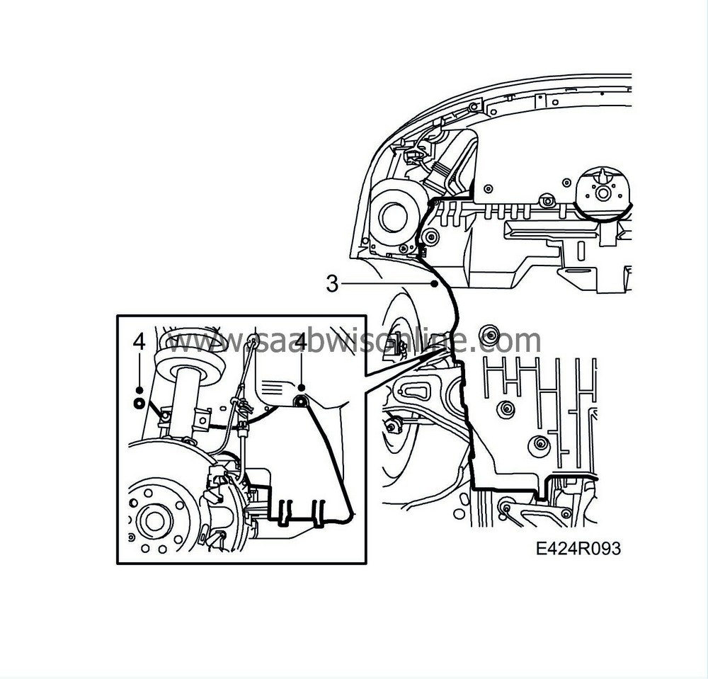
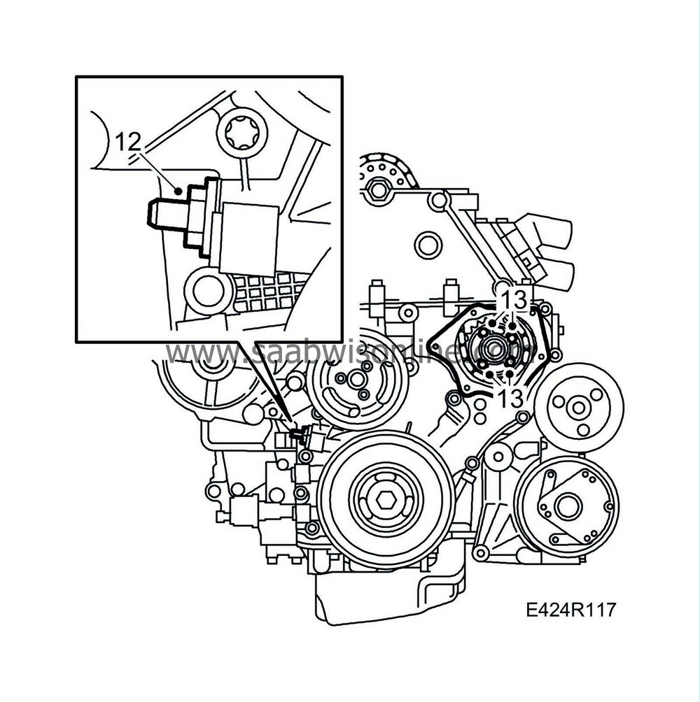
Remove the crankshaft position sensor.
|
|
9.
|
Lower the car to the floor.
|
|
10.
|
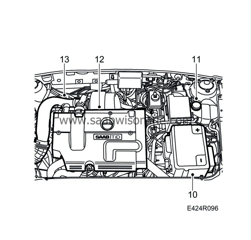
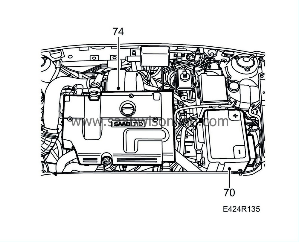
Remove the battery cover and disconnect the negative battery cable.
|
|
11.
|
Loosen the coolant expansion tank cap to release any pressure.
|
|
12.
|
Remove the upper engine cover.
|
|
13.
|
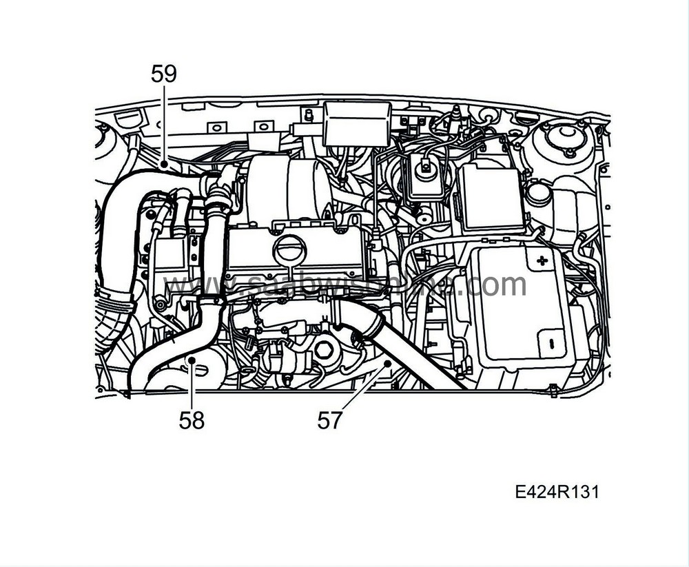
Remove the intake manifold from the mass air flow sensor to the turbocharger and camshaft cover.
|
|
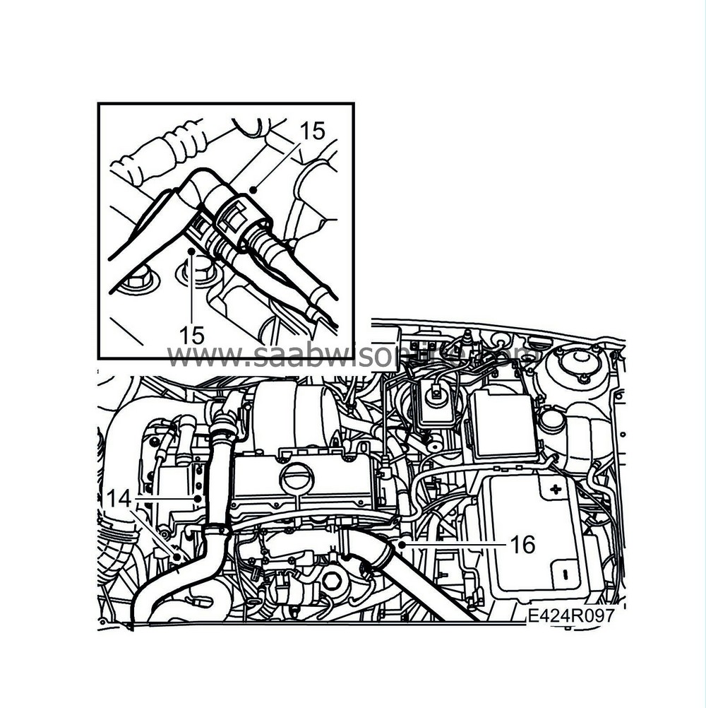
14.
|
Remove the charge air hose with charge air pipe from the turbocharger and the charge air pipe on the fan cowling. Plug the connections.
|
|
16.
|
Remove the turbocharger delivery pipe with hose from the throttle body and move it aside.
|
|
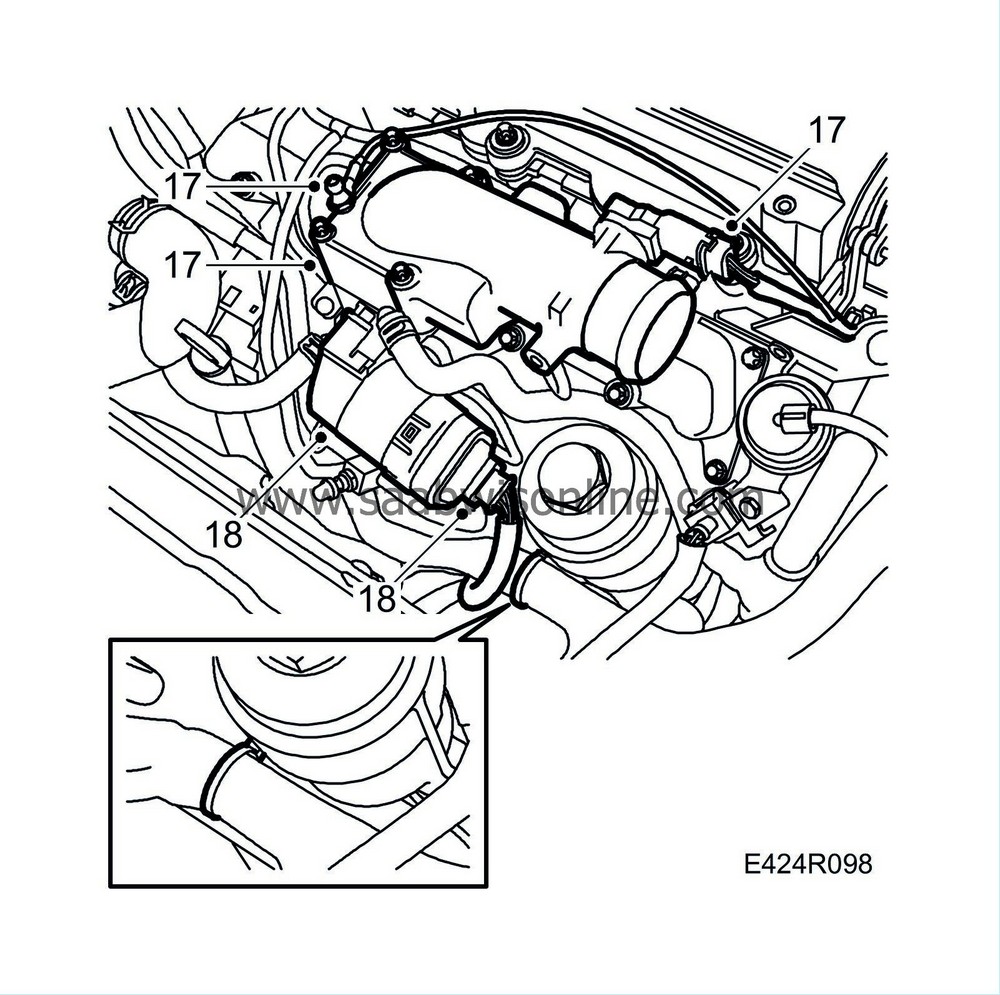
17.
|
Unplug the pressure/temperature sensor cable and disconnect the ground cable. Remove the throttle body.
|
|
18.
|
Unplug the connector and remove the EGR valve from the intake manifold.
|
|
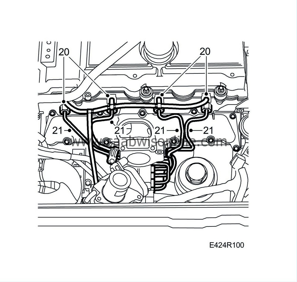
20.
|
Place a receptacle under the car to collect any spilled fuel. Detach the fuel return hoses from the fuel bridges.
|
|
21.
|
Mark the position of the fuel rails and their clips and remove them.
|
|
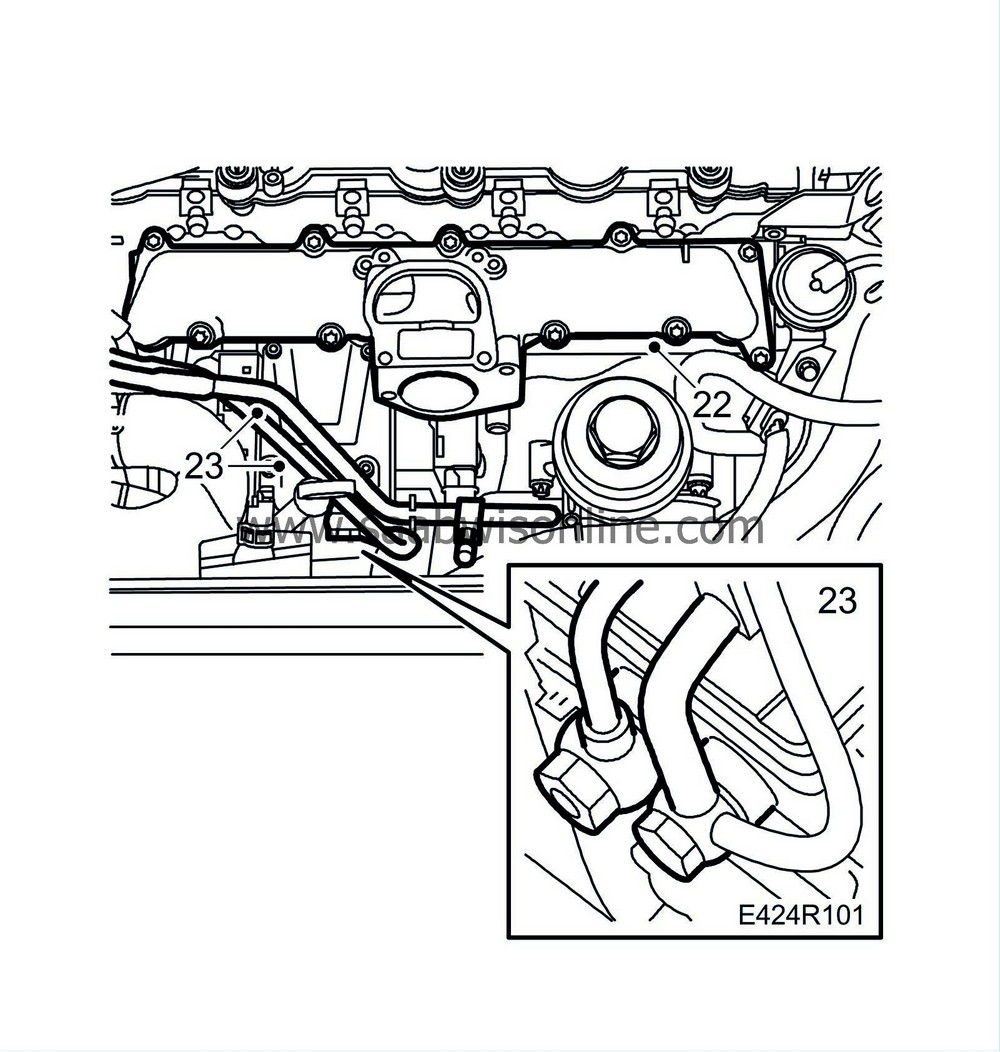
22.
|
Remove the upper portion of the intake manifold.
|
|
23.
|
Detach the fuel inlet and return lines from the fuel distribution pump.
|
|
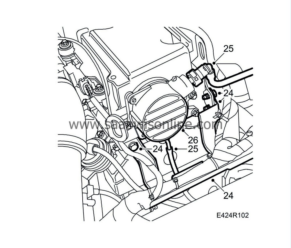
24.
|
Undo the cable rail and move it aside.
|
|
25.
|
Undo the vacuum hose to the brake servo and the vacuum hose connected to the bottom of the vacuum pump.
|
|
26.
|
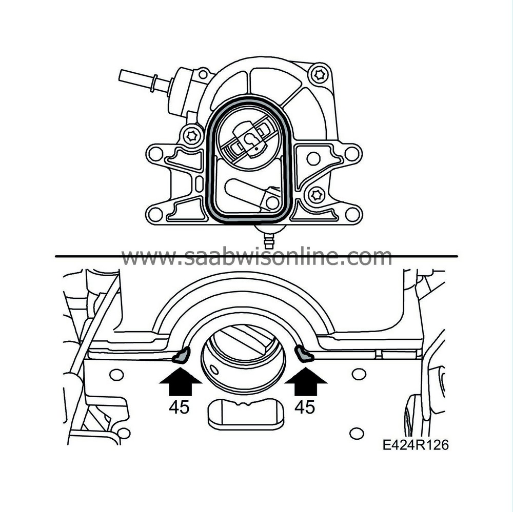
Remove the four vacuum pump retaining bolts and carefully lift off the vacuum pump and its adapter. Be prepared with a rag or similar to collect any spilled oil.
|
|
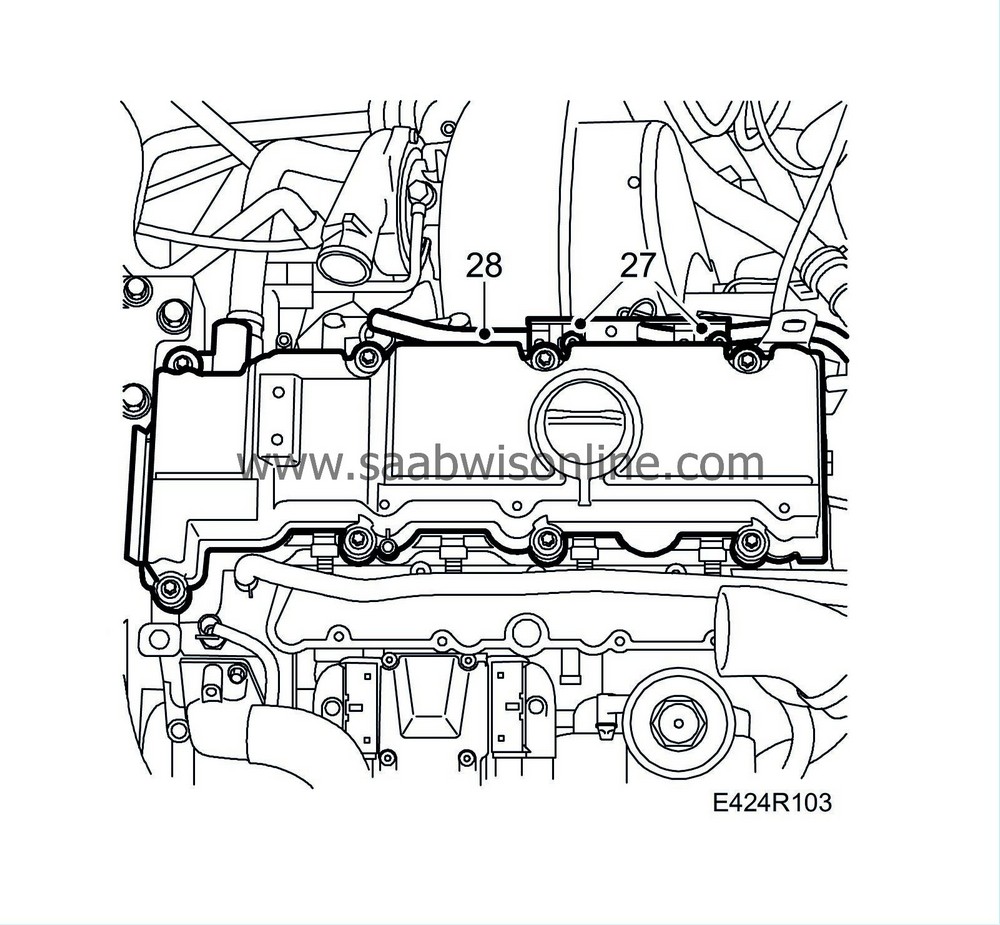
27.
|
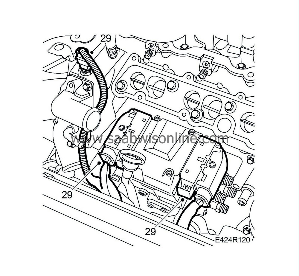
Undo the rear cable harness mounting on the camshaft cover.
|
|
28.
|
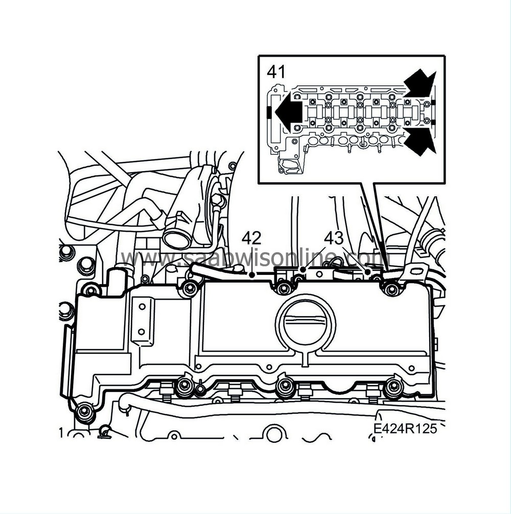
Remove the camshaft cover.
|
|
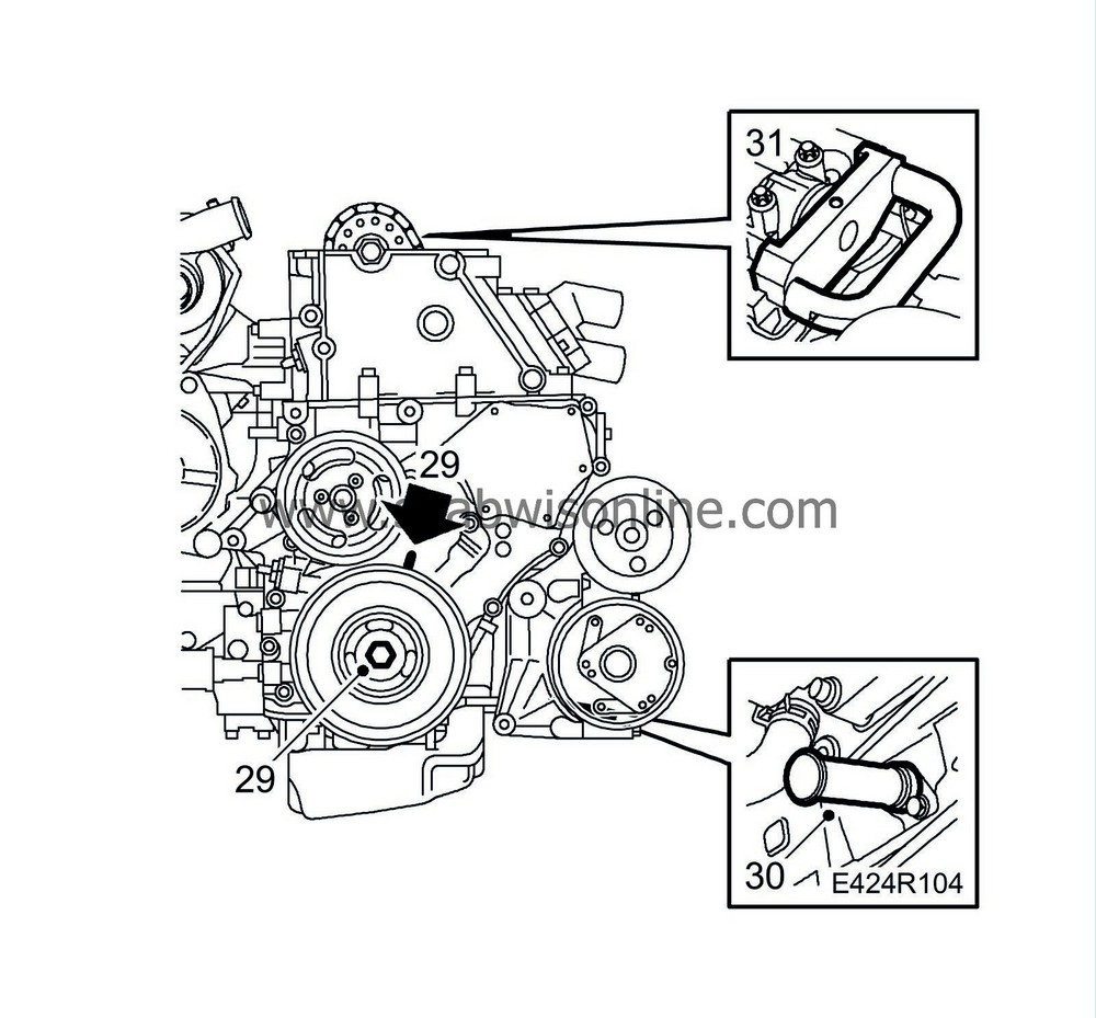
29.
|
Turn the crankshaft to just before the mark for top dead centre in cylinder 1. Make sure both cam lobes for cylinder 1 are pointing up.
|
|
30.
|
Insert
83 95 352 Setting tool, crankshaft
into the hole for the crankshaft position sensor. Push the tool somewhat inward at the same time as the crankshaft is turned to the zero point. The tool will then go into a recess in the crankshaft and lock it.
|
|
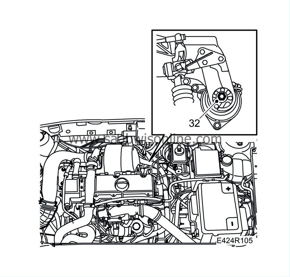
32.
|
Remove the nut on the rear engine pad.
|
|
33.
|
Remove the nut and the vibration damper on the right-hand engine pad.
|
|
34.
|
Take the weight of the engine carefully with a jack.
|
|
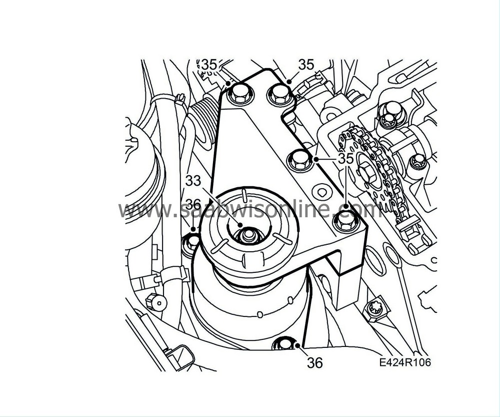
35.
|
Remove the upper bracket.
|
|
36.
|
Dismantle the right-hand engine pad.
|
|
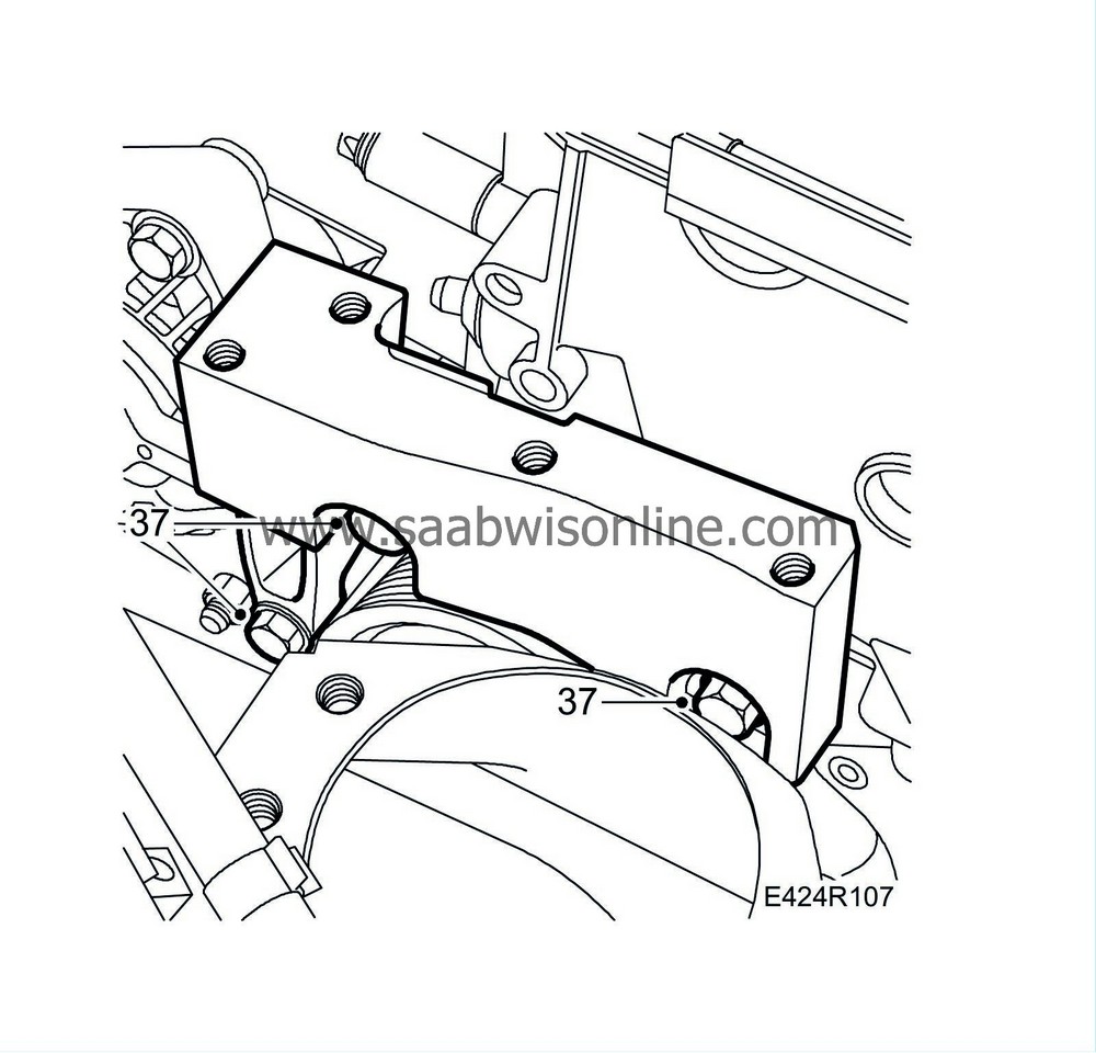
37.
|
Raise the engine with the jack and remove the lower bracket. Lower the engine slightly.
|
|
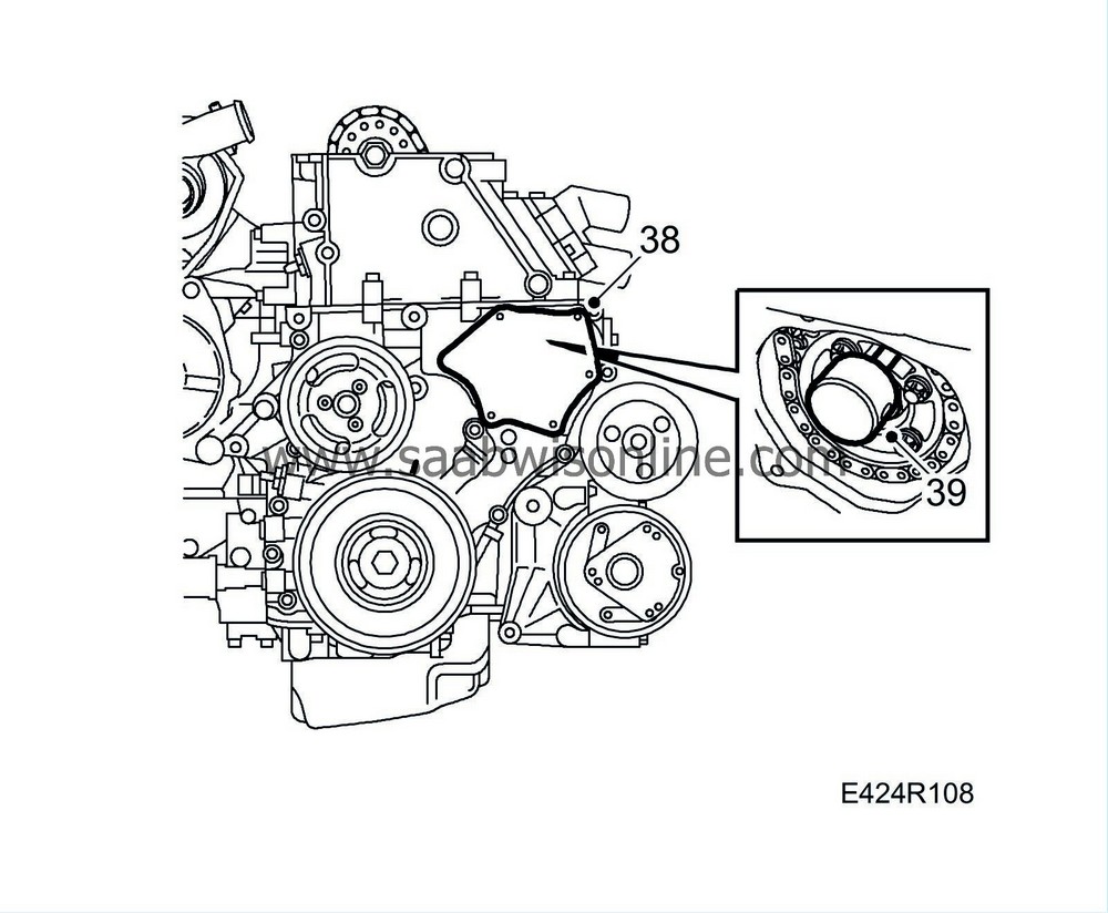
38.
|
Remove the screws for the timing cover plate, carefully insert a putty knife behind the cover and prise it off carefully.
|
Important
|
|
Take care, otherwise the cover can be distorted and cause leaks.
|
|
|
|
|
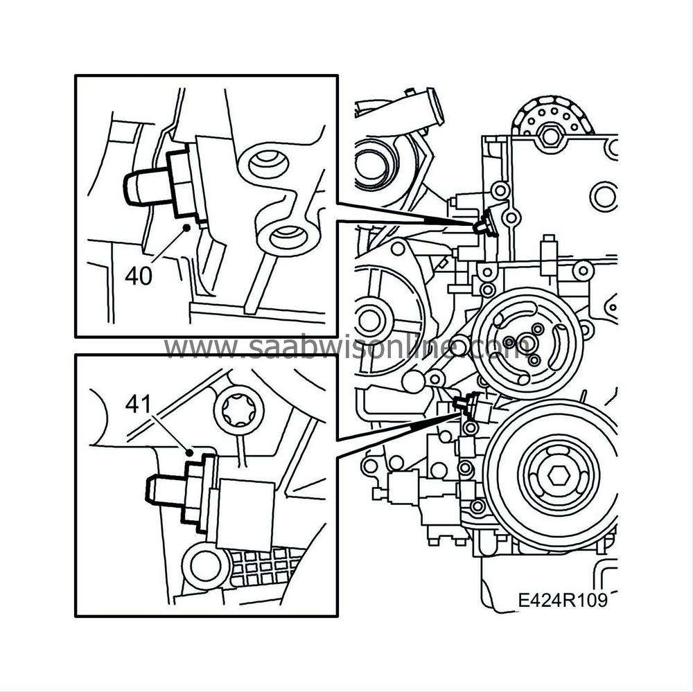
40.
|
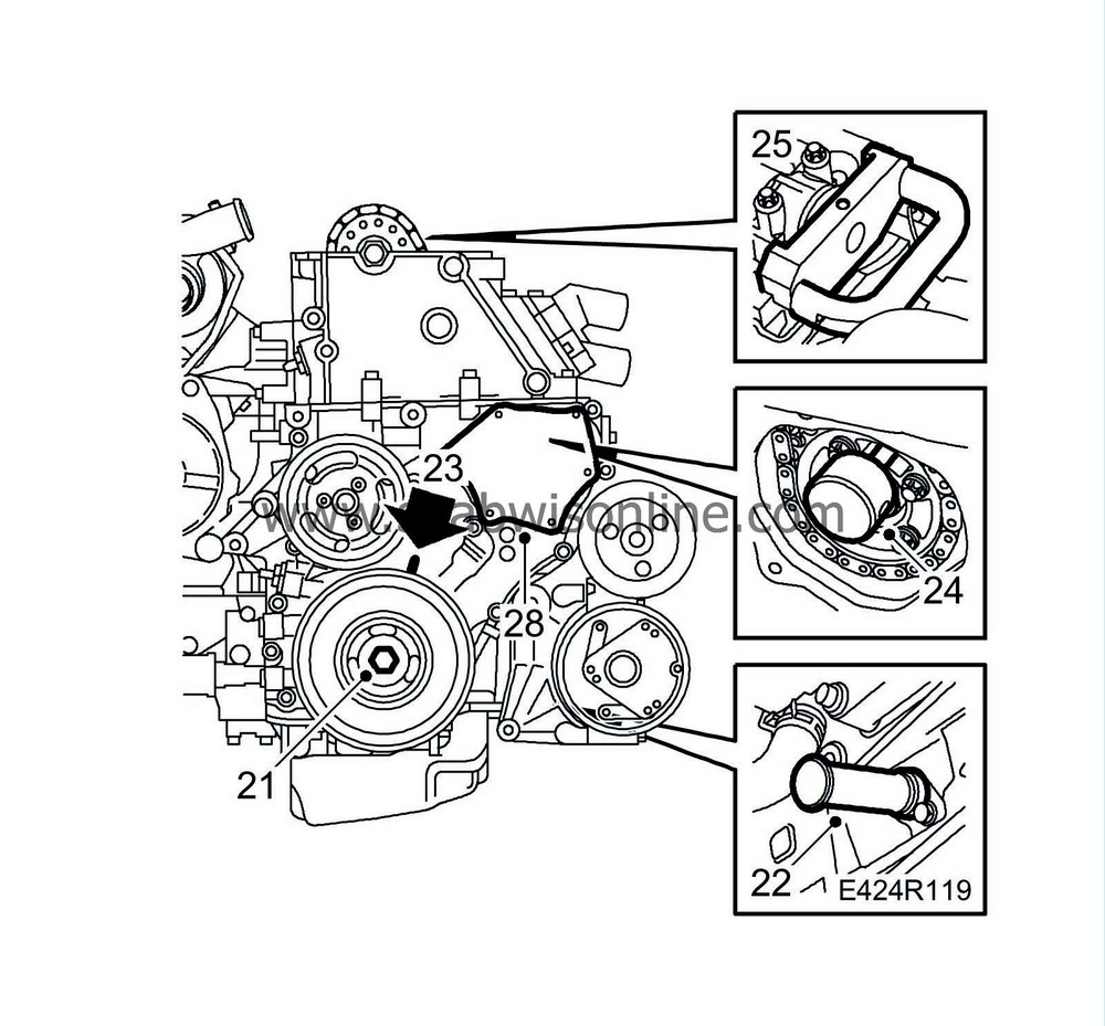
Remove the upper timing chain tensioner.
|
|
41.
|
Remove the lower timing chain tensioner.
|
|
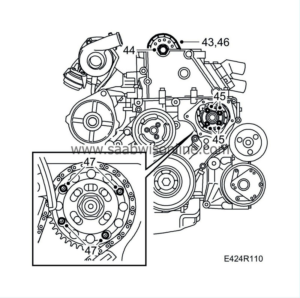
43.
|
Fasten the upper timing chain to the camshaft sprocket with a cable tie.
|
|
44.
|
Remove the camshaft sprocket using an open spanner for support in the hexagonal recess on the camshaft.
|
|
45.
|
Undo the bolts in the fuel distribution pump sprocket and remove it.
|
Important
|
|
Remove only the four bolts,
not
the centre nut.
|
|
|
|
|
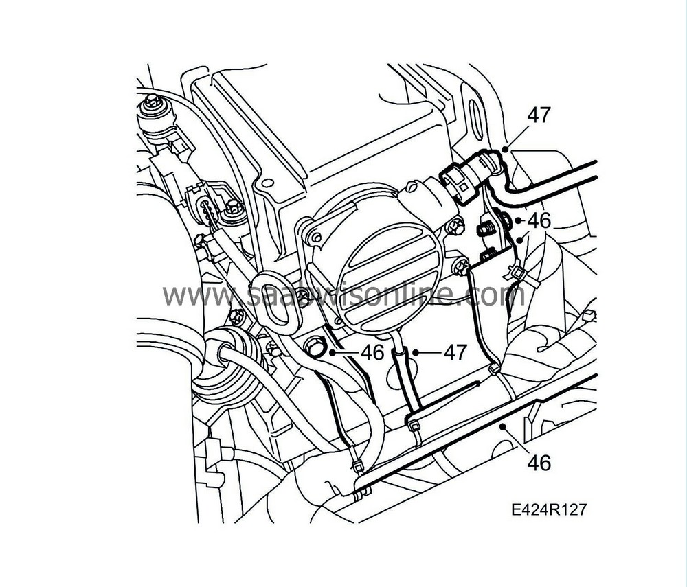
46.
|
Pull up the chain and remove it.
|
|
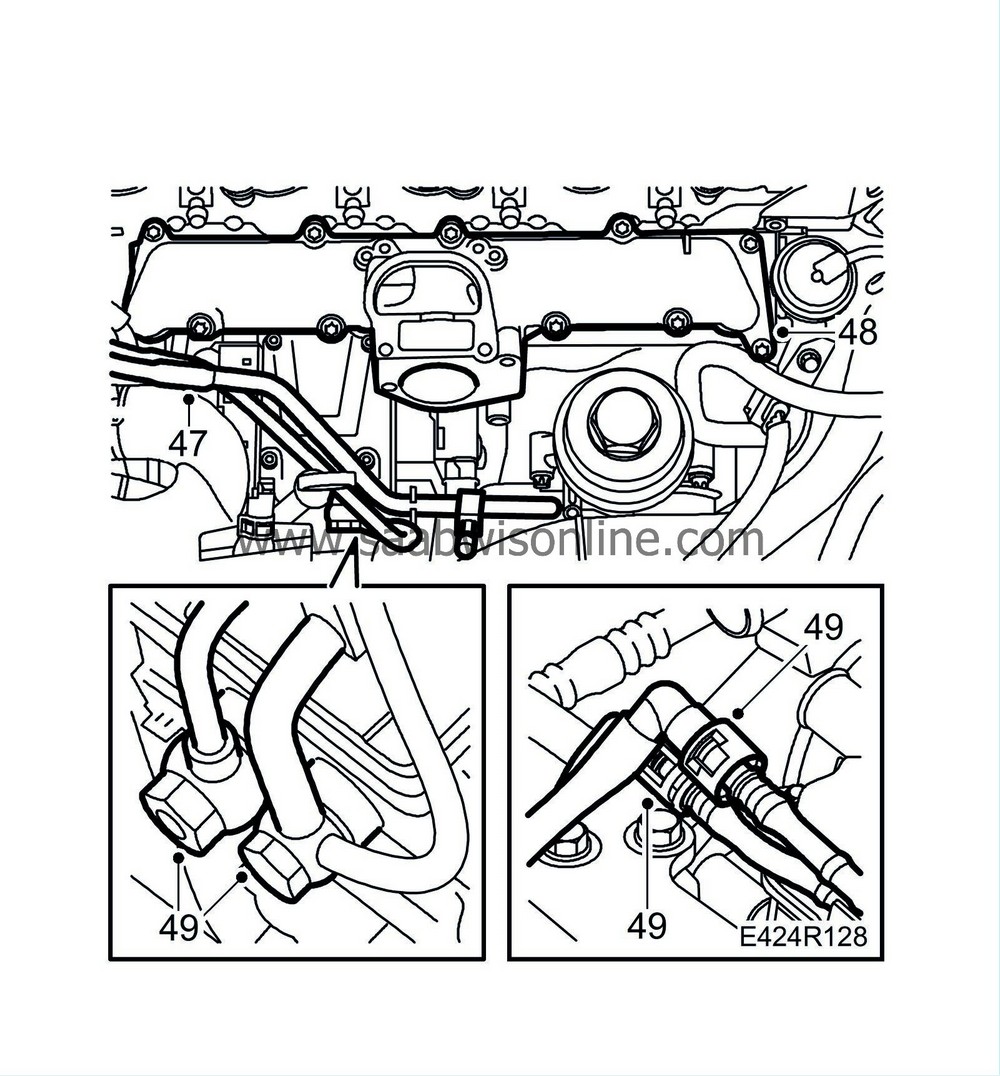
47.
|
Remove the four retaining bolts on the fuel distribution pump that are accessible through the hole in the timing cover.
Use
83 95 543 Tool, fuel pump gear
.
|
|
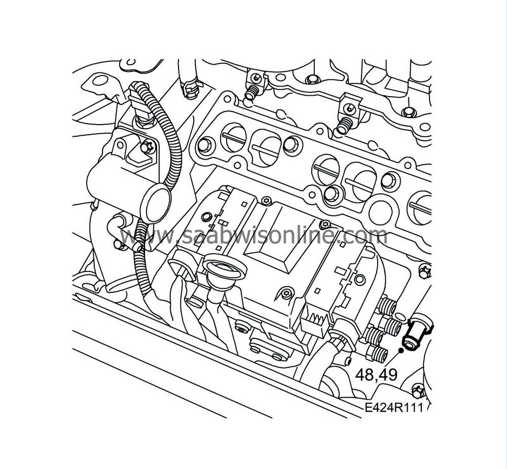
48.
|
Place a receptacle under the car. Undo the drain nipple (8 mm Allen key). Connect a hose in the engine block nipple. Drain the coolant.
|
|
49.
|
Remove the drain nipple.
|
|
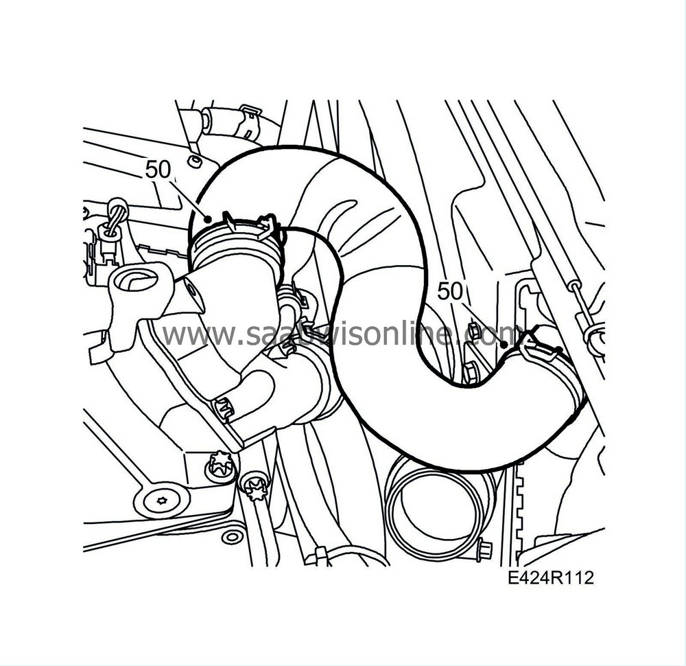
50.
|
Detach the coolant hoses from the thermostat housing and the radiator connection.
|
|
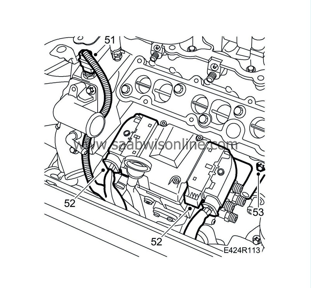
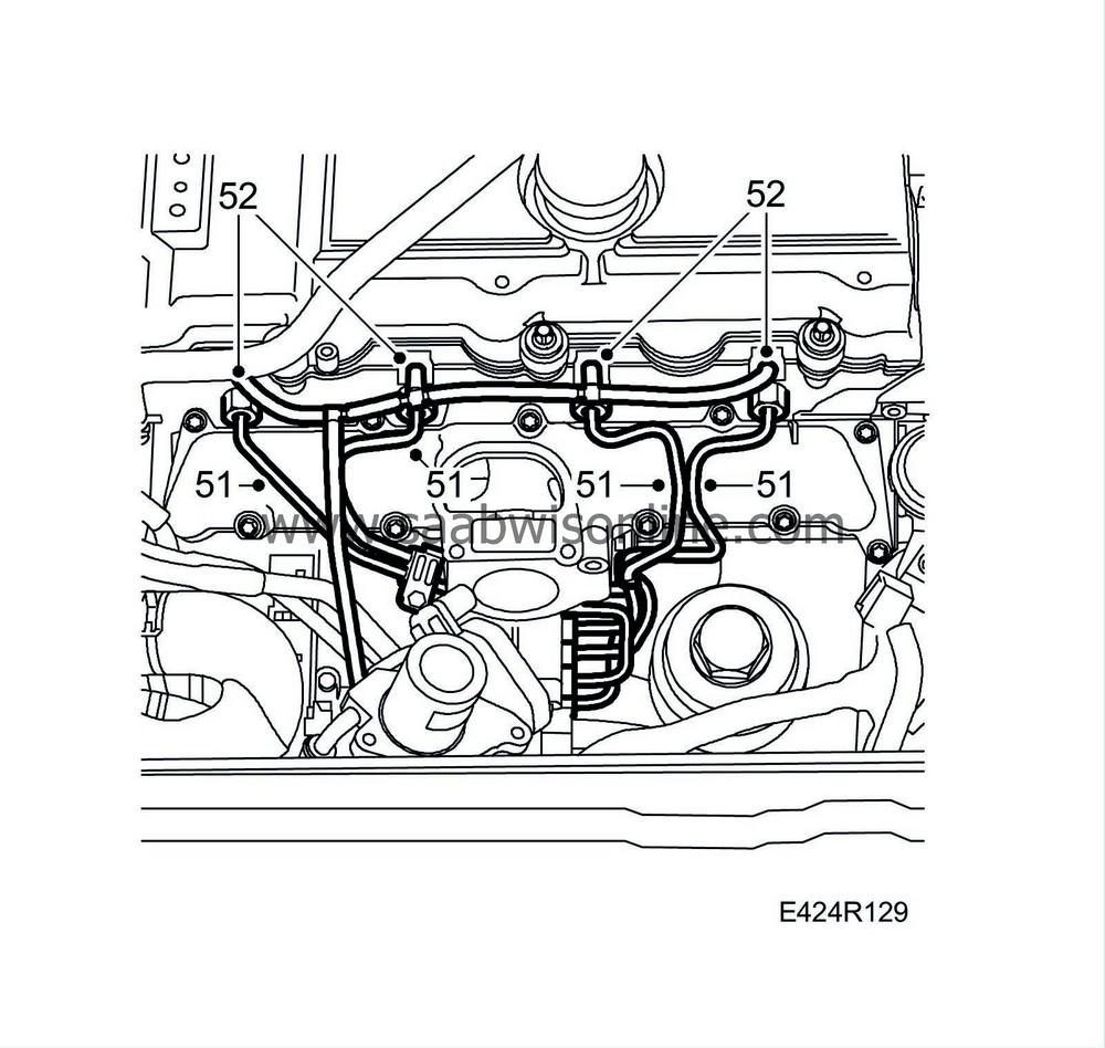
51.
|
Unplug the coolant temperature sensor connector.
|
|
52.
|
Unplug the connectors from the fuel pump control module.
|
Important
|
|
ESD-SENSITIVE COMPONENT
|
|
Earth yourself by touching the car body before plugging in / unplugging components.
Do not touch the component pins.
Read
Before changing a control module
before changing a control module.
|
|
|
|
|
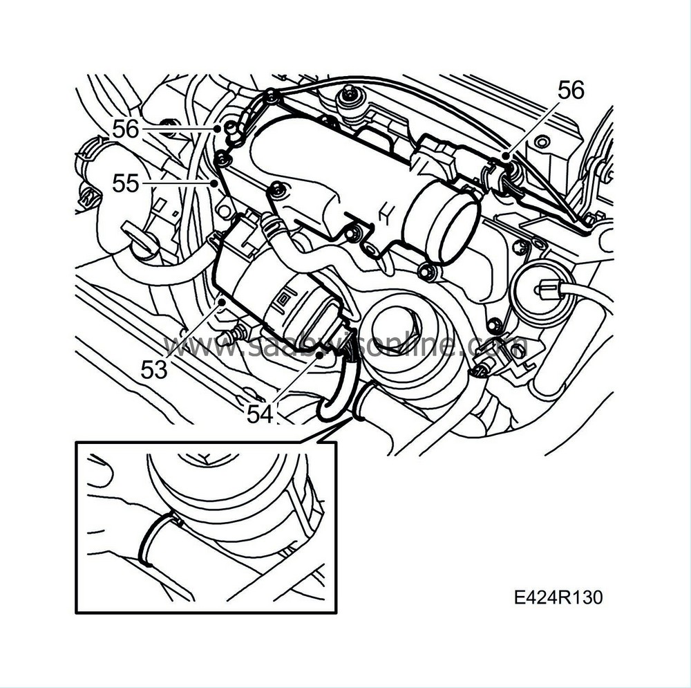
53.
|
Undo the bracket bolt from the cylinder block and remove the fuel pump.
|
|
1.
|
Clean the sealing surfaces.
|
|
2.
|
Fit a new O-ring onto the fuel distribution pump, lubricate the O-ring with acid-free Vaseline and position the pump on the cylinder block.
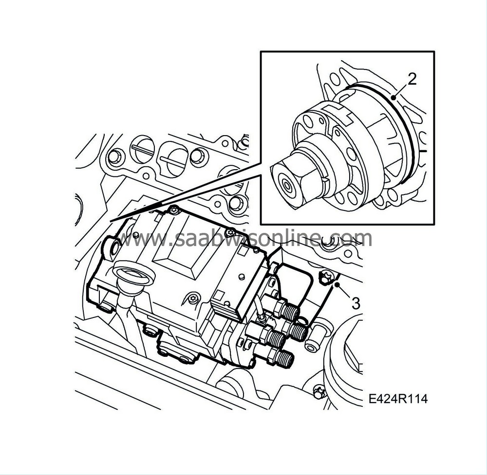
Transfer the bracket to the new pump if it is replaced.
Tightening torque: 20 Nm (15 lbf ft)
|
|
3.
|
Insert the bracket bolt in the cylinder block, but do not tighten it.
|
|
6.
|
Tighten the bolt securing the bracket to the cylinder block.
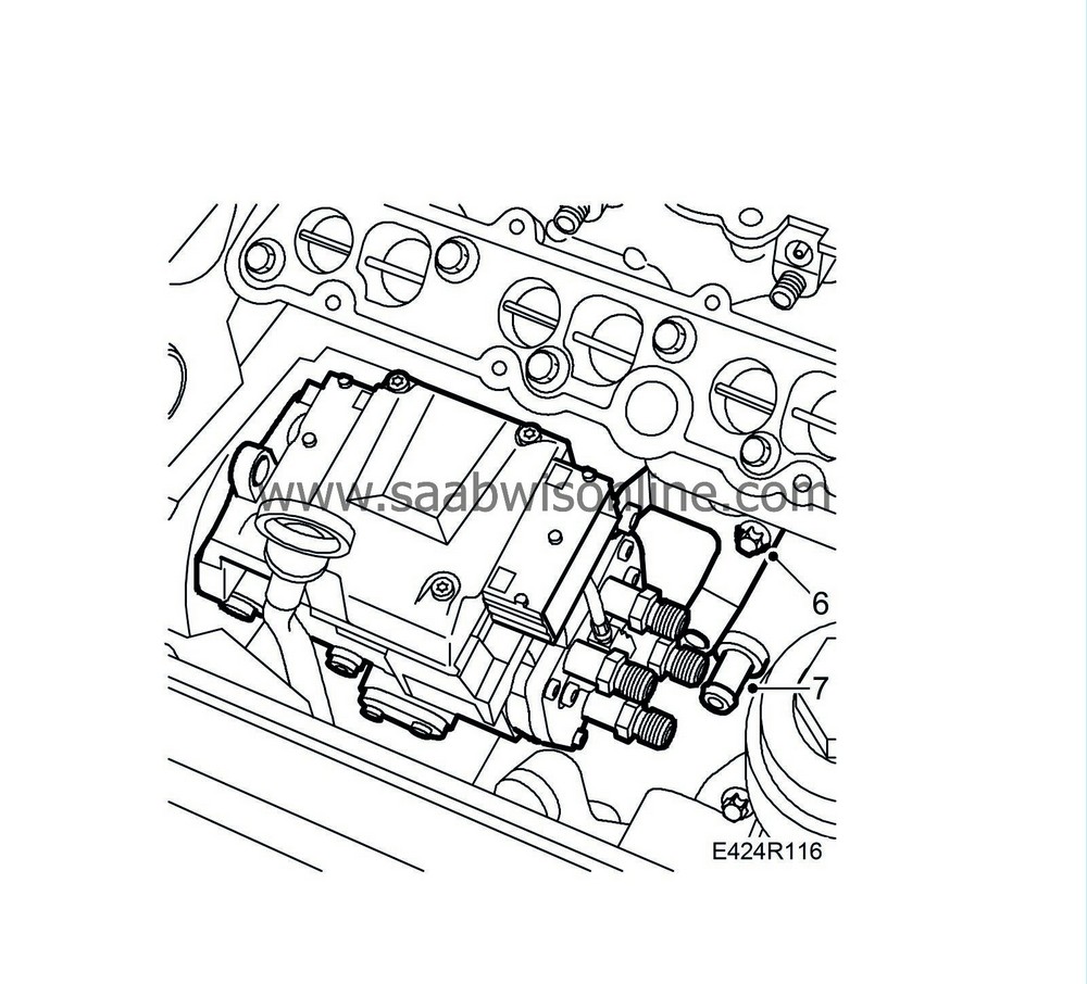
Tightening torque: 20 Nm (15 lbf ft)
|
|
7.
|
Fit the engine block drain plug with a new O-ring.
|
|
8.
|
Remove the inspection gauge from the fuel distribution pump.
|
|
9.
|
Release the upper timing chain, position the sprocket on the fuel distribution pump, fit the sprocket with one bolt, fit the chain and tighten the bolts on the sprocket by hand.
|
Important
|
|
The arrow on the pinion must be in line with the recess on the flange and the hole in the pump.
|
|
|
|
|
11.
|
Position the camshaft sprocket on the camshaft.
|
|
12.
|
Replace the chain tensioner for the lower timing chain using a new gasket.
Tightening torque: 60 Nm (44 lbf ft)
|
|
13.
|
Remove the inspection gauge from the fuel distribution pump and tighten the bolts on the sprocket.
Tightening torque: 20 Nm (15 lbf ft)
|
|
15.
|
Make sure the camshaft gear runs freely on the camshaft and fit a new bolt. Tighten it by hand.
|
|
17.
|
Fix the position for the adapter on the camshaft sprocket by lightly twisting it counter-clockwise with a ratchet handle. Tighten the adjustment screw on the tool.
|
Important
|
|
Inspection gauge 83 95 337 must be easy to remove and replace the entire time. If this is not the case, the tool adjustment screw can be loosened slightly.
|
|
|
|
|
18.
|
Tighten the bolts on the camshaft gear.
Tightening torque: 90 Nm (67 lbf ft) + 60°
|
|
19.
|
Replace the chain tensioner for the upper timing chain using a new gasket.
Tightening torque: 60 Nm (44 lbf ft)
|
|
20.
|
Remove all tools and gauges.
|
|
21.
|
Turn the crankshaft two revolutions to just before the mark for top dead centre in cylinder 1. Make sure both cam lobes for cylinder 1 are pointing up.
|
|
22.
|
Insert
83 95 352 Setting tool, crankshaft
into the hole for the crankshaft position sensor. Push the tool somewhat inward at the same time as the crankshaft is turned to the zero point. The tool will then go into a recess in the crankshaft and lock it.
|
|
23.
|
Make sure the markings on the crankshaft pulley and the timing cover are in line. The arrow on the single timing chain pulley on the fuel distribution pump must also be in line with the recess in the pump.
|
|
26.
|
Remove all the inspection gauges.
|
|
27.
|
Cover the opening in the timing cover with a lint-free rag clean the sealing surface from any remnants of gasket. Clean the sealing surface on the cover plate as well.
|
|
28.
|
Apply a bead of
87 81 841 Silicone flange sealant
about 2 mm thick on the cover plate, remove the rag from the timing cover and fit the cover plate.
Tightening torque: 6 Nm (5 lbf ft).
|
|
29.
|
Plug in the connectors of the fuel pump control module and the coolant temp. sensor.
|
|
30.
|
Fit the coolant hoses to the thermostat housing and the radiator connection.

|
|
31.
|
Fit the lower bracket.

Tightening torque: 40 Nm (30 lbf ft) +90°
|
|
32.
|
Fit the right-hand engine pad.
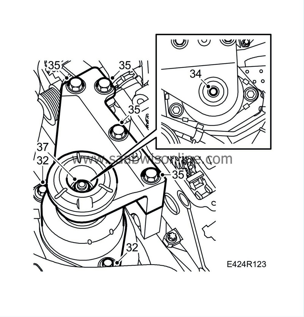
Tightening torque: 47 Nm (35 lbf ft)
|
|
33.
|
Fit the upper bracket without tightening the bolts.
|
|
34.
|
Lower the jack until the upper bracket comes in contact with the engine pad. Adjust the upper bracket so that the engine pad stud is situated as close as possible to the upper bracket hole.
|
|
35.
|
Fit the engine pad vibration damper and nut and tighten the upper bracket retaining bolts.
Tightening torque: 40 Nm (30 lbf ft) +60°
|
|
36.
|
Lower the engine completely and remove the jack.
|
|
37.
|
Tighten the nut on the right-hand engine pad.
Tightening torque 105 Nm (77 lbf ft)
|
|
38.
|
Fit the nut of the rear engine pad.

Tightening torque: 47 Nm (35 lbf ft)
|
|
39.
|
Clean any gasket remains from the sealing surfaces on the cylinder head.
|
|
40.
|
Place a new gasket on the camshaft cover. The bolts have sleeves where the gasket is fitted.
|
|
42.
|
Place the camshaft cover on the cylinder head and tighten the screws.
Tightening torque: 8 Nm (6 lbf ft).
|
|
43.
|
Fit the rear cable harness mounting on the camshaft cover.
|
|
44.
|
Clean the sealing surfaces on the vacuum pump and cylinder head.
|
|
45.
|
Place a new gasket on the vacuum pump, apply sealant
87 81 841 Silicone flange sealant
as illustrated and fit the pump together with the adapter.
Tightening torque: 8 Nm (6 lbf ft).
|
|
47.
|
Connect the vacuum hoses to the vacuum pump.
|
|
48.
|
Clean the sealing surfaces of the upper portion of the intake manifold. Fit the upper portion using a new gasket.
Tightening torque: 10 Nm (7 lbf ft)
|
|
49.
|
Fit the fuel inlet and return lines to the fuel pump with new seals but do not tighten the connections yet.
Connect the fuel lines to the lines from the tank, adjust the lines to the recess in the camshaft cover and tighten the connections on the fuel pump.
Grip the fuel lines to prevent them from twisting when tightened.
Tightening torque: 25 Nm (19 lbf ft)
|
|
50.
|
Inspect the tapered fuel rail connections and change the pipe if any of them are damaged.
|
|
51.
|
Fit the fuel rails.
Tightening torque: 25 Nm (19 lbf ft)
|
|
52.
|
Fit new fuel return hoses to the fuel bridges.
|
|
53.
|
Fit the EGR valve using a new O-ring.
Tightening torque: 10 Nm (7 lbf ft)
|
|
54.
|
Plug in the EGR valve connector and connect its coolant hoses.
|
|
55.
|
Fit the throttle body with a new gasket.
Tightening torque: 10 Nm (7 lbf ft)
|
|
56.
|
Fit the ground cable and the pressure/temperature sensor connector on the throttle body.
|
|
57.
|
Connect the turbocharger delivery pipe with hose to the throttle body.
|
|
58.
|
Remove the plugs, connect and fit the turbocharger delivery pipe with hose to the turbocharger, camshaft cover and turbocharger delivery pipe on the fan cowling.
|
|
59.
|
Fit the intake manifold from the mass air flow sensor to the turbo and the hose for the crankcase ventilation.
Tightening torque, mass air flow sensor: 3.5 Nm (2.5 lbf ft)
|
|
61.
|
Fit the crankshaft position sensor using a new O-ring.
Tightening torque: 8 Nm (6 lbf ft).
|
|
62.
|
Fit the front torque arm bolt and tighten the rear one.
Tightening torque, front bolt: 90 Nm (66 lbf ft) +90°
Tightening torque, rear bolt: 50 Nm (37 lbf ft) +120°
|
|
63.
|
Fit the belt tensioner and tighten the upper bolt first.

Tightening torque: 42 Nm (31 lbf ft).
|
|
64.
|
Tighten the lower bolt.
Tightening torque: 23 Nm (17 lbf ft).
|
|
65.
|
Fit the multigroove belt and make sure it is positioned correctly over the belt pulleys.
|
|
66.
|
Fit the belt circuit's cover.

|
|
67.
|
Fit the lower engine cover.
|
|
68.
|
Fit the wheel, see
Wheels
.
|
|
69.
|
Lower the car to the floor.
|
|
70.
|
Connect the negative battery cable and fit the battery cover.
|
|
72.
|
Add coolant to around 20 mm above the mark on the expansion tank. See
Coolant
.
|
|
73.
|
Fit the upper engine cover.
|
|
75.
|
Adjust the clock, SID and calibrate AC/ACC.
|


