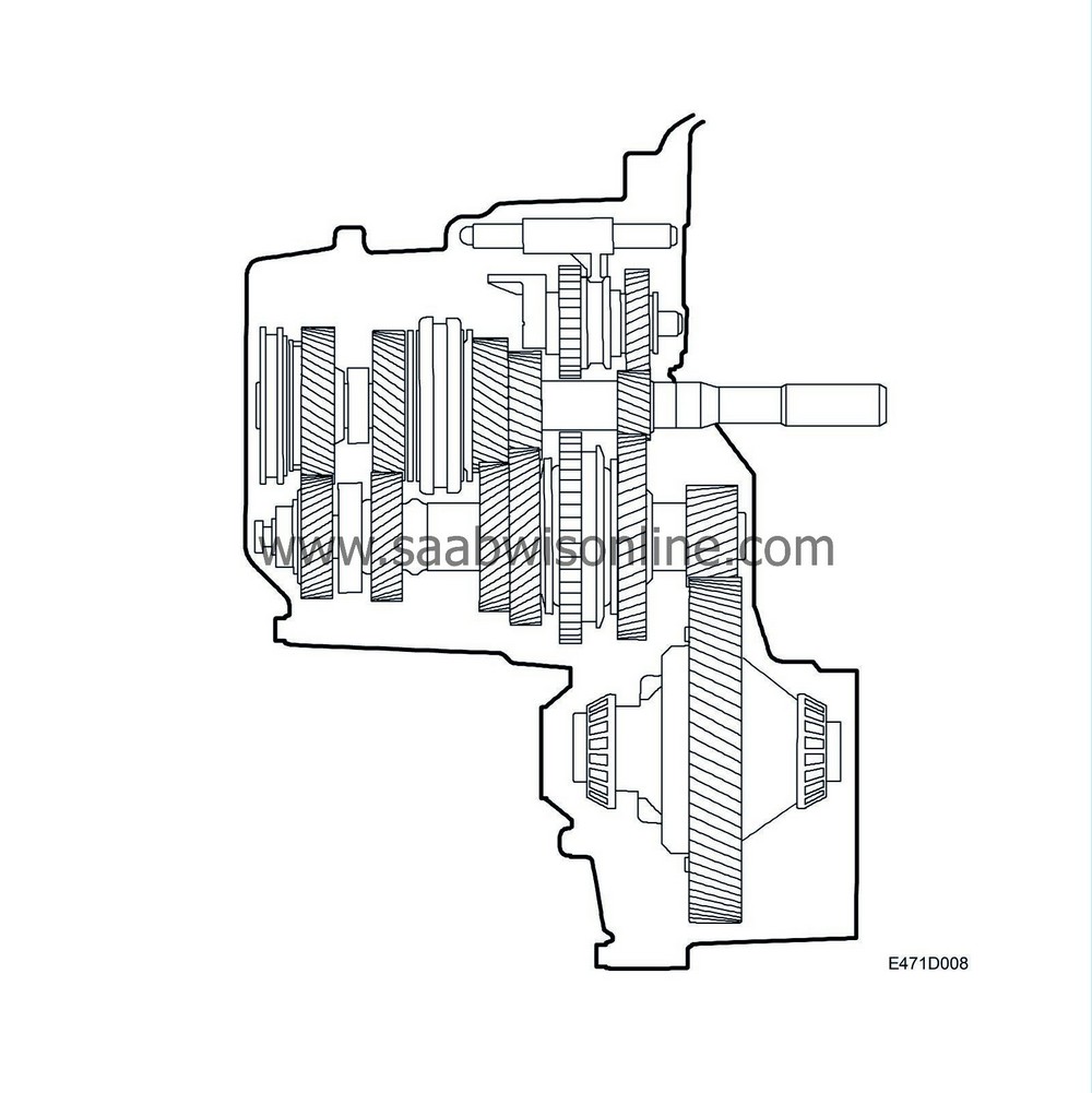
Basic design
Input shaft, output shaft and reverse gear shaft
|
5.
|
Synchromesh sleeve, 3rd-4th
|
|
9.
|
Synchromesh sleeve, 5th
|
|
12.
|
Synchromesh sleeve, 1st-2nd
|
The manual gearbox is a 5 speed box. All gears have synchromesh. The gearbox has relatively small rotating masses and thus low moment of inertia to be retarded at each gearchange. This makes gear changing easy and smooth and interior wear on baulk rings and sleeves is almost non-existent. The baulk rings are located on the input and output shafts.
Note that the gearwheels on the input shaft are called pinions (are driving), while the gear wheels on the output shaft are called gear wheels (are driven). The pinions on the 3rd, 4th and 5th gears are mounted in needle bearings to achieve lowest possible losses from friction and thus a high degree of efficiency.
For better synchromesh function, the 1st and 2nd gears have 2 baulk rings. The 3rd, 4th and 5th gears have 3 leaf springs mounted between each baulk ring and its hub. This is to ensure that the baulk ring cannot move and generate noise when not under load.
Input and output shafts have been mounted with taper roller bearings to achieve maximum rigidity in the shafts under load. The output shaft's roller bearing has been placed inside the final gear drive, which gives the shaft maximum insensitivity to high loads.
The workings of the gearbox are shown in the diagram. Power transmission from the engine is via the clutch, directly to the input shaft.
Power transmission 1st gear: When the car is driven in 1st gear, power is transmitted via the 1st pinion on the input shaft to the output shaft when the 1st gear wheel is secured to the output shaft, on which it is mounted, by the 1st/2nd synchromesh sleeve.
Power transmission, 2nd gear: In a similar way to 1st gear, but the 1st/2nd synchromesh sleeve instead secures the 2nd gear wheel to the output shaft.
Power transmission in 3rd gear: When driving in 3rd gear, power is transmitted via the 3rd pinion on the input shaft to the output shaft when the 3rd pinion is secured to the input shaft, on which it is mounted, by the 3rd/4th synchromesh sleeve.
Power transmission, 4th gear: In a similar way to the 3rd gear, but the 3rd/4th synchromesh sleeve instead secures the 4th pinion to the input shaft.
Power transmission, 5th gear: In a similar way to 3rd and 4th gears, but the 5th synchromesh sleeve instead secures the 5th pinion to the input shaft.
Power transmission, reverse gear: The reverse gear has an extra shaft (the reverse gear shaft). This shaft holds a journalled reverse gear wheel which is constantly meshed with the 1st gear pinion on the input shaft and a journalled reverse gear pinion which is constantly meshed with the 1st/2nd synchromesh sleeve on the output shaft. When driving in reverse gear, the power is transmitted from the 1st pinion on the input shaft to the reverse gear wheel by the synchromesh sleeve in this position meshing the reverse gear pinion with the reverse gear wheel. The power is then transmitted from the reverse gear pinion to the 1st/2nd synchromesh sleeve which drives the output shaft. Since the power from the input shaft to the output shaft goes via a third shaft, the desired direction of rotation is achieved for the reverse gear.


