PRE-RELEASE
Fuel pump (in car), V6
| Fuel pump (in car), V6 |
| To remove |
|
||||||||||||||||||||||
| Important | ||
|
Be particulary observant regardning cleanliness when working on the fuel system. Loss of function may occur due to very small particles. Prevent dirt and grime from entering the fuel system by cleaning the connections and plugging pipes and lines during disassembly. Use 82 92 948 Plugs, A/C system assembly. Keep components free from contaminants during storage. |
||
| 1. |
Raise the car. Remove the lower engine cover and right-hand cover.

|
|
| 2. |
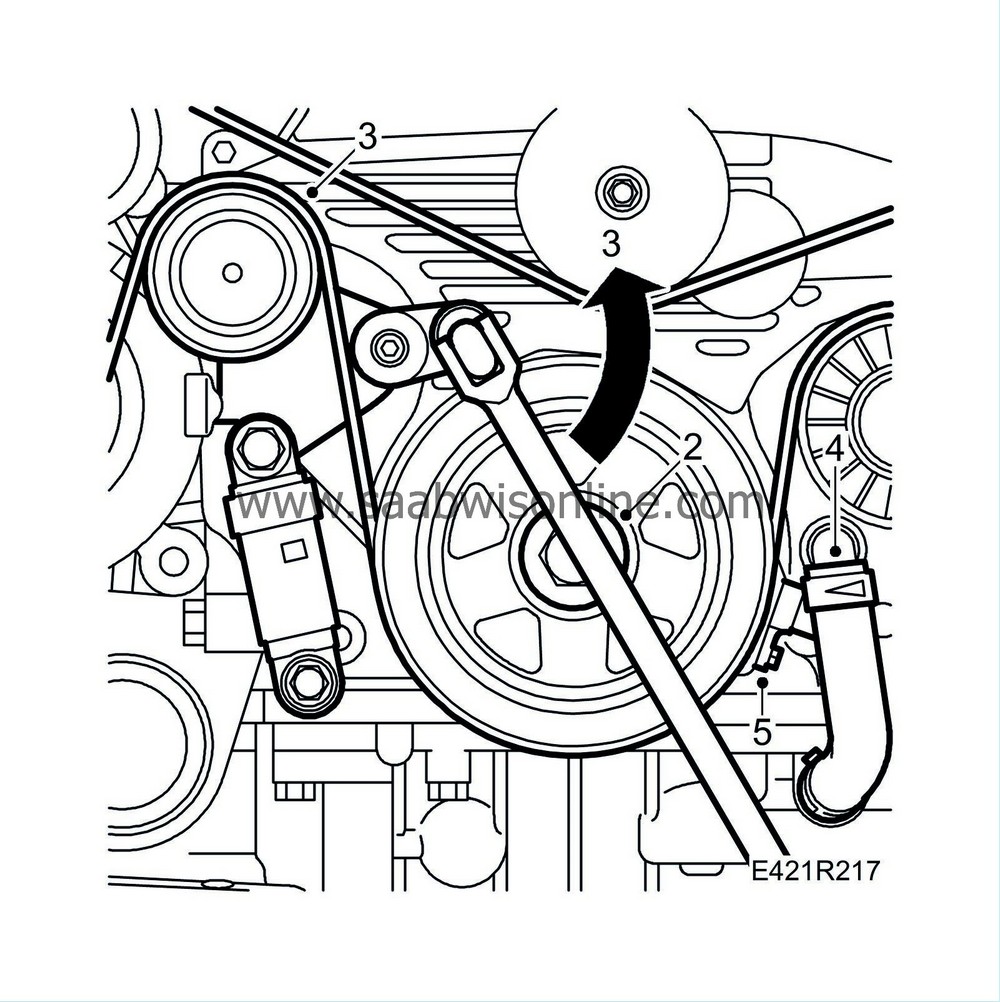
Undo the crankshaft pulley bolt. Use the tool 32 025 019 Holding tool, camshaft sprocket.
|
|
| 3. |
Detension and remove the multigroove V-belt. Remove the belt tensioner.
|
|
| 4. |
Remove the oil return hose.
|
|
| 5. |
Unplug the connector from the tachometer, engine speed (408).
|
|
| 6. |
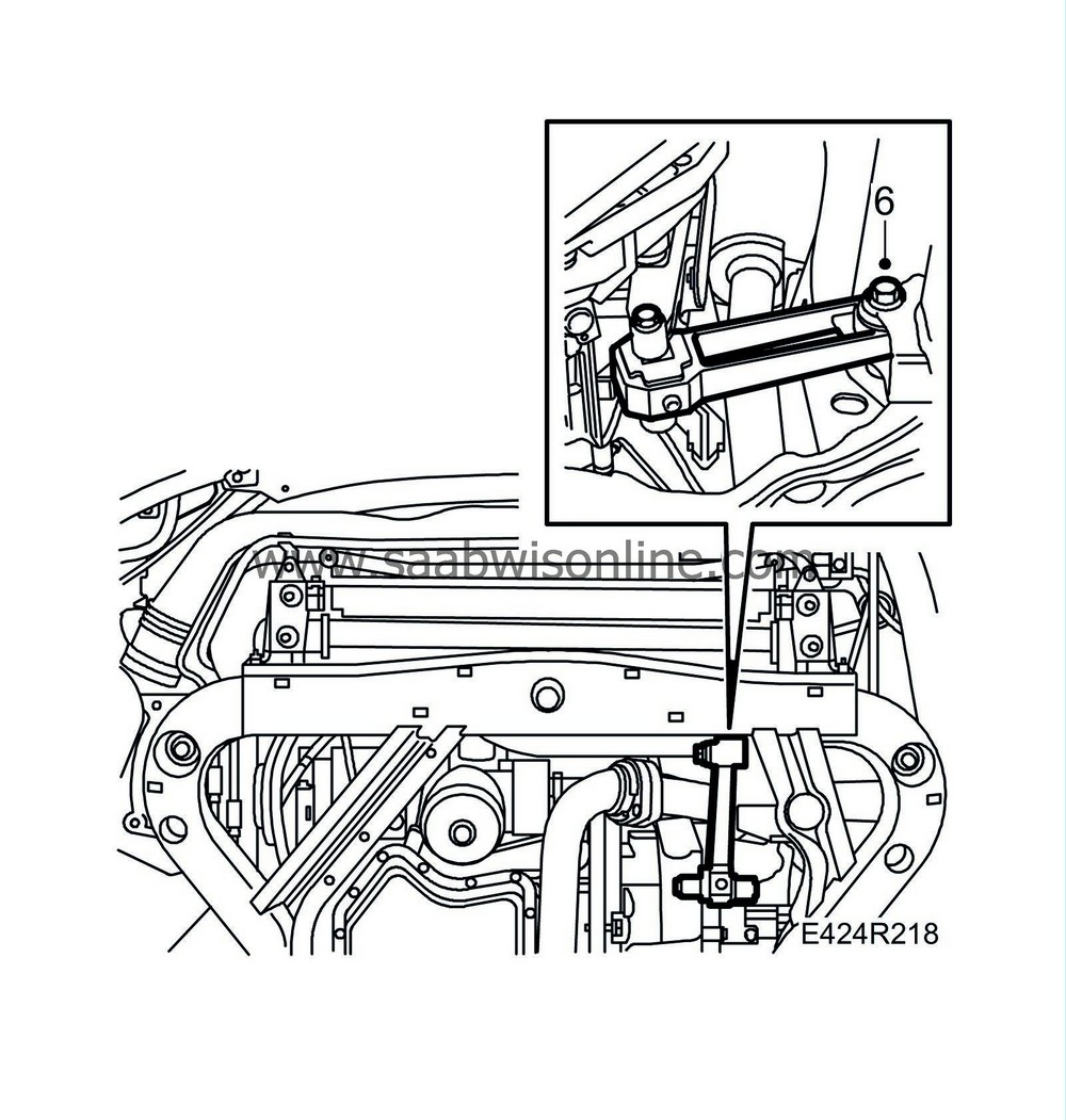
Remove the front bolt on the front torque arm.
|
|
| 7. |
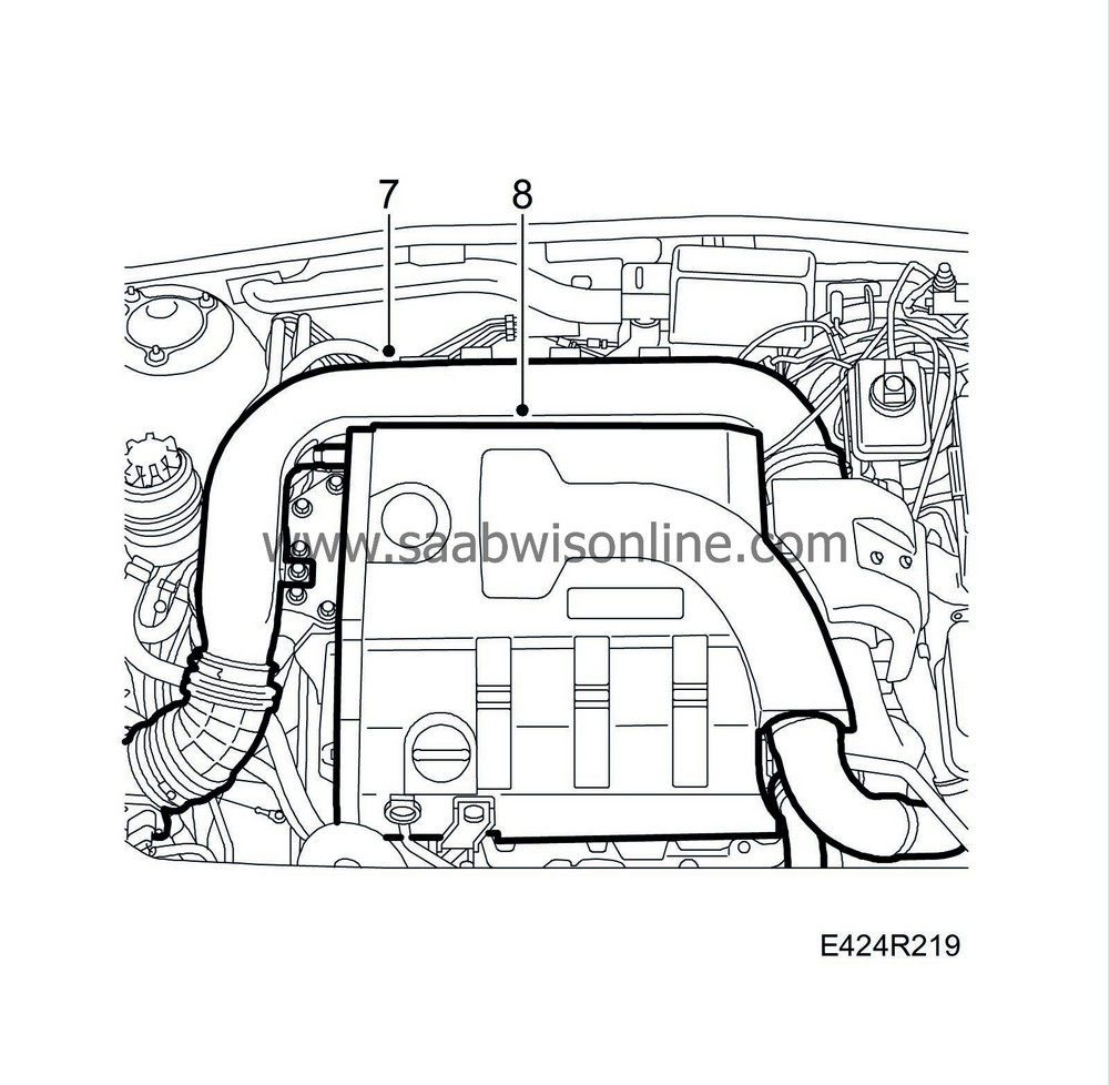
Lower the car and remove the intake manifold between mass air flow sensor and turbocharger.
|
|
| 8. |
Remove the upper engine cover.
|
|
| 9. |
Remove the nut on the rear engine pad.

|
|
| 10. |
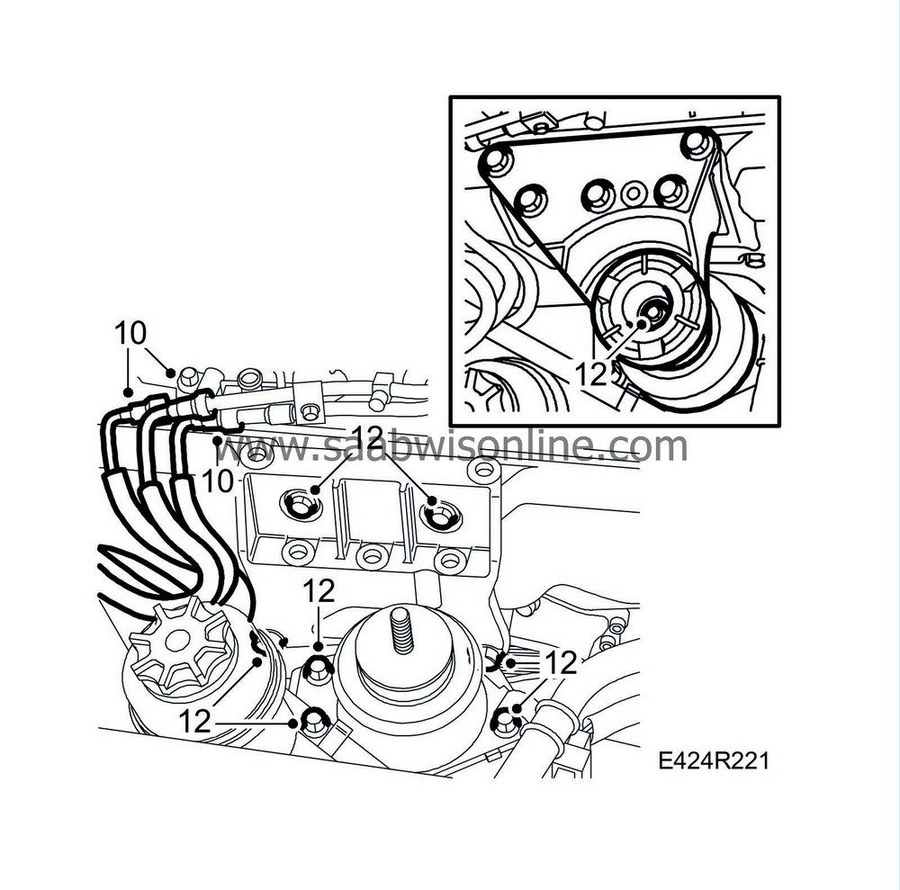
Clean and undo the fuel lines' quick couplings. Use
83 95 261 Fuel line tool
. Use a rag to deal with any spilled fuel. Plug the lines.
|
|
| 11. |
Unload the engine with a jack. Insert a wooden block, approx. 300X100 mm, between the jack and the oil pan. Lift the side of the oil pan closest to the crankshaft/pulley.
|
|
| 12. |
Remove the right-hand engine mounting with upper bracket and engine pad. Raise the engine slightly more to remove the engine bracket bolts.
|
|
| 13. |
Lower the engine to normal height.
|
|
| 14. |
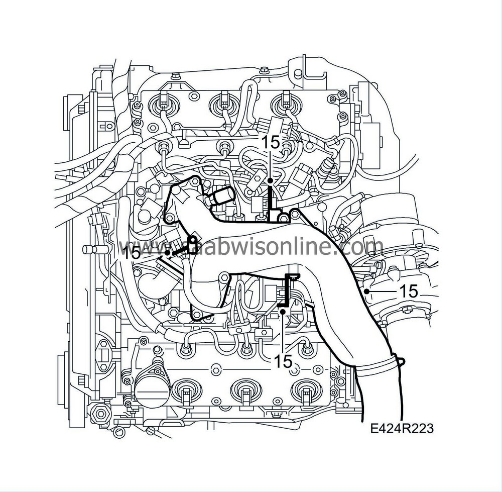
Unplug the connectors, remove the front cable duct and fold away the engine harness. Remove the ground cables.

|
|
| 16. |
Remove the turbo's bracket. Clean and remove the fuel pipe and fuel distributor.
Certain cars : Locate the spacer washer under the fuel distributor. See illustration. 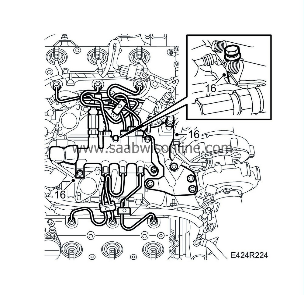
|
|
| 17. |
Undo the crankcase ventilation hose from the T-pipe. Remove the coolant pipe's brackets.

|
|
| 18. |
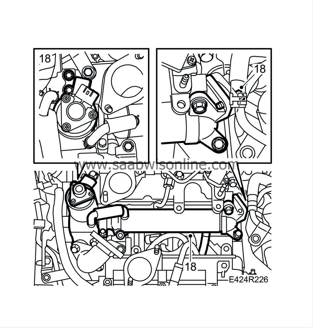
Remove the EGR valve with coolant hose. Remove and fold aside the water jacketed EGR pipe with EGR valve.
|
|
| 19. |
Remove the crankcase ventilation pipe.

|
|
| 20. |
Remove the fuel delivery pipe and lower intake manifold from the rear and front cylinder bank.
|
|
| 21. |
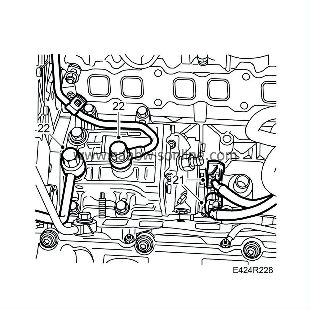
Plug the holes to the cylinder head. Unplug the connectors to the fuel pump.
|
|
| 22. |
Remove the fuel supply pipe and fuel return pipe.
|
|
| 23. |
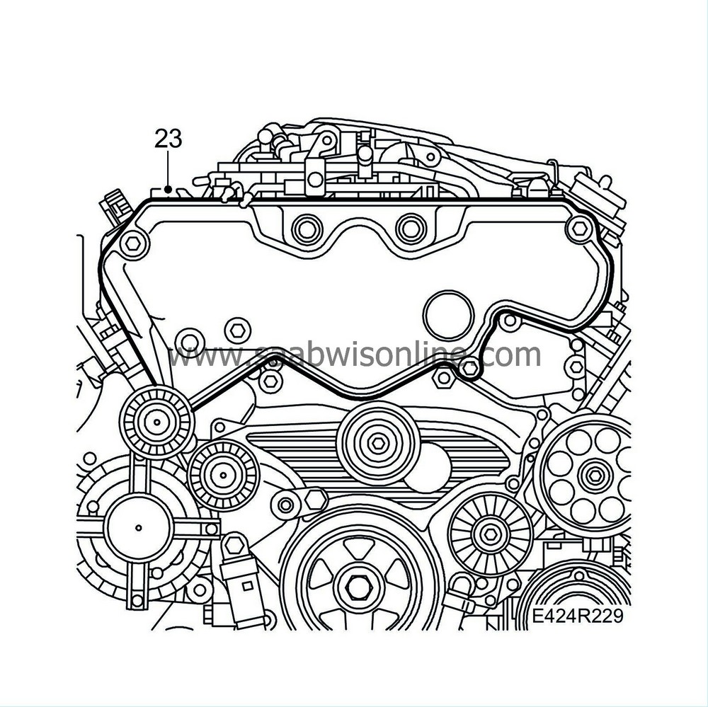
Remove the cam belt cover.
|
|
| 24. |
Zero the engine, aligning the crankshaft pulley, camshaft pulleys and fuel pump pulley with the markings on the engine. If the fuel pump pulley's marking does not correspond when the crankshaft pulley is reset then the gear transmission's markings must be checked, see
Timing cover with gear transmission
.
Camshaft pulleys' marking : LH, front cylinder bank RH, rear cylinder bank 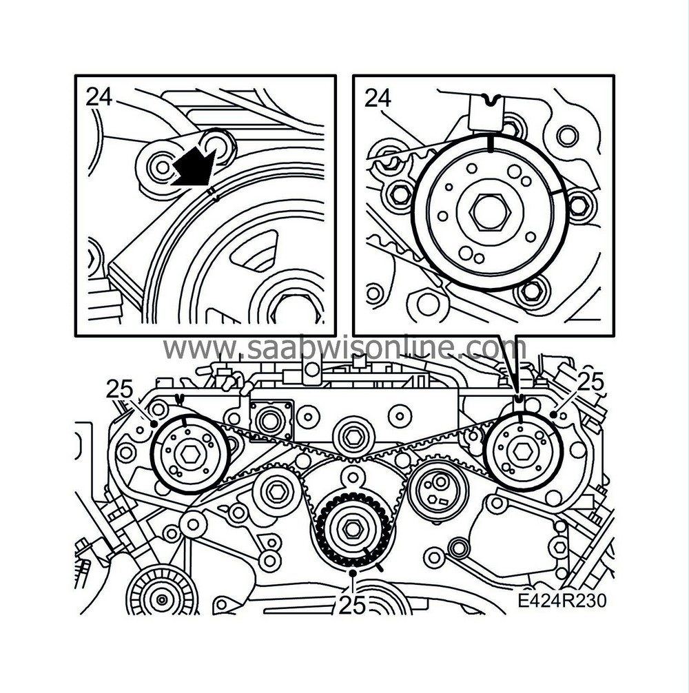
|
|
| 25. |
If the markings on the belt are unclear, remark the belt to correspond with the marks on the pulleys.
|
|
| 26. |
Release the tension on the tension pulley by turning it with a 10 mm Allen key and inserting a 6 mm drill or similar in the hole. Remove the tension pulley by loosening the bolt and pulling the tension pulley out at the same time.

|
|
| 27. |
Remove the timing belt and idler pulley.
|
|
| 28. |
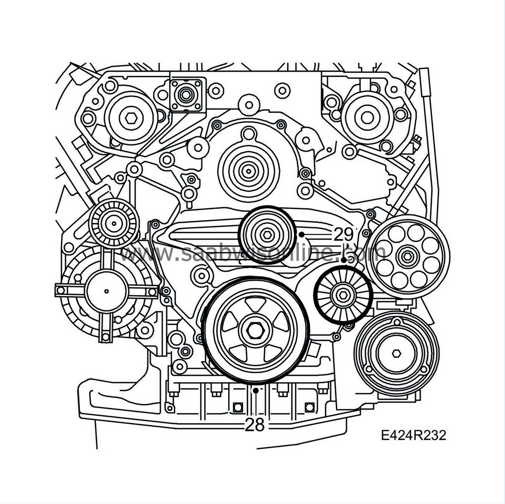
Check that the pulley's marking corresponds with the timing cover. Remove the pulley.
|
|
| 29. |
Remove the Poly-V belt's idler pulley.
|
|
| 30. |
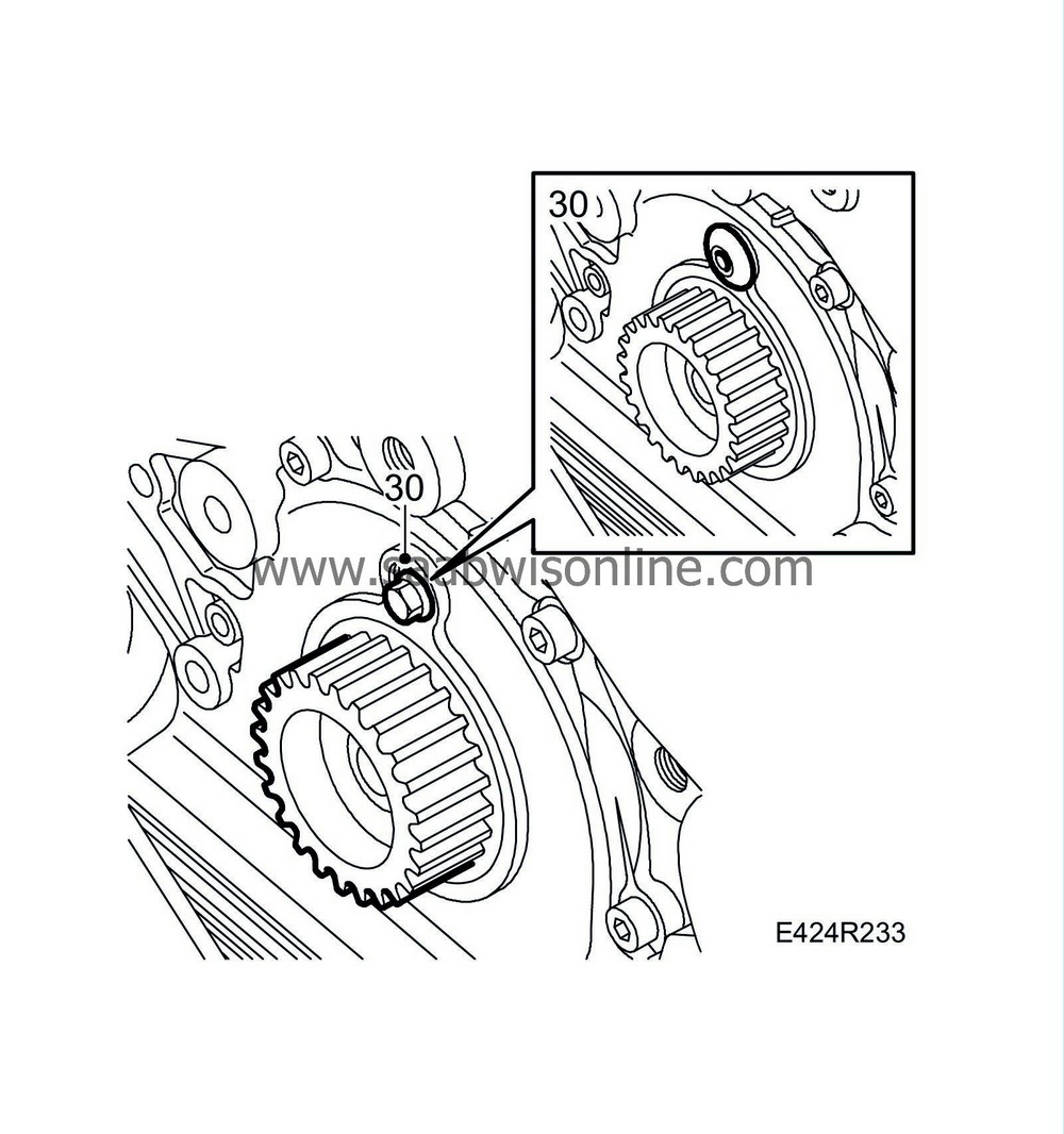
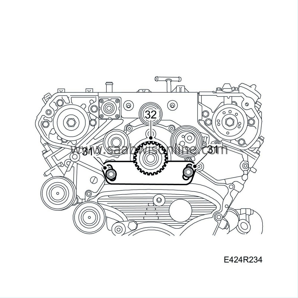
Remove the plug from the timing cover and fit an M6x20 bolt into the inner pinion on the fuel pump.
|
|
| 31. |
Fit
EN-47646 Holding tool, fuel pump
to the pinion and remove the nut and the holding tool.
|
|
| 32. |
Remove the camshaft pulley from the fuel pump shaft.
|
|
| 33. |
Remove the timing cover. Remove the seals and clean the sealing surfaces of the cover of gasket remains.

|
|
| 34. |
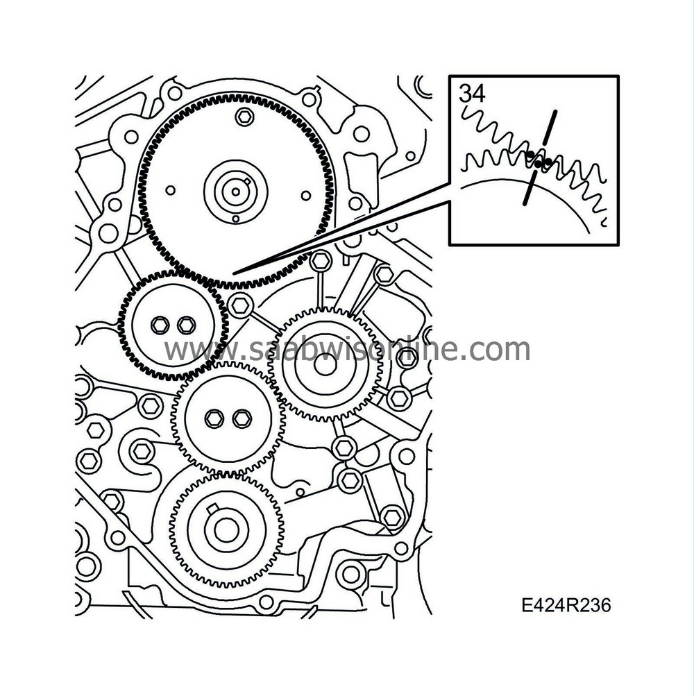
Remove the locking screw from the fuel pump gear. Mark out the intermediate pinion's position against the fuel pump gear.
|
|
| 35. |
Fit two M6 bolts into the holes on the fuel pump gear. Tighten the bolts alternately until the outer part of the pinion and the spring comes loose.

|
|
| 36. |
Fit two M6 bolts in the holes on the inner section of the fuel pump gear. Tighten the bolts alternately and tap carefully with a plastic mallet against the end of the shaft until the gear loosens from the shaft.
|
|
| 37. |
Remove the fuel pump. Take note of the position of the locating bolts, see illustration.

|
|
| To fit |
| 1. |
Clean the timing cover's sealing surface to the engine.
|
|
| 2. |
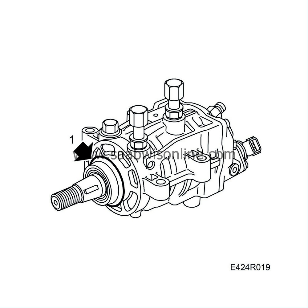
Fit a new seal to the fuel pump. Grease the seal with acid-free petroleum jelly.
|
|
| 3. |
Fit the fuel pump. Take note of the position of the locating bolts.
Tightening torque: 21 Nm (15 lbf ft) 
|
|
| 4. |
Set the rear half of the fuel pump gear in a vice and insert the spring. Set two M6 bolts into the front portion. Add the front portion and use a screwdriver and the M6 bolts to turn it clockwise so that the teeth lie correctly against each other. Lock into position with an M6x20 bolt.

|
|
| 5. |
Fit the fuel pump gear on the shaft in accordance with the previous marking. Undo the bolt approx. 7 mm.
|
|
| 6. |
Clean the sealing surfaces with
Cleaning agent, Loctite Super Clean 7063
or similar. Add a bead of flange sealant
90 543 772 Silicone flange sealant
into the recess around the cover and fit the timing cover.
Tightening torque: 25 Nm (18 lbf ft) 
|
|
| 7. |
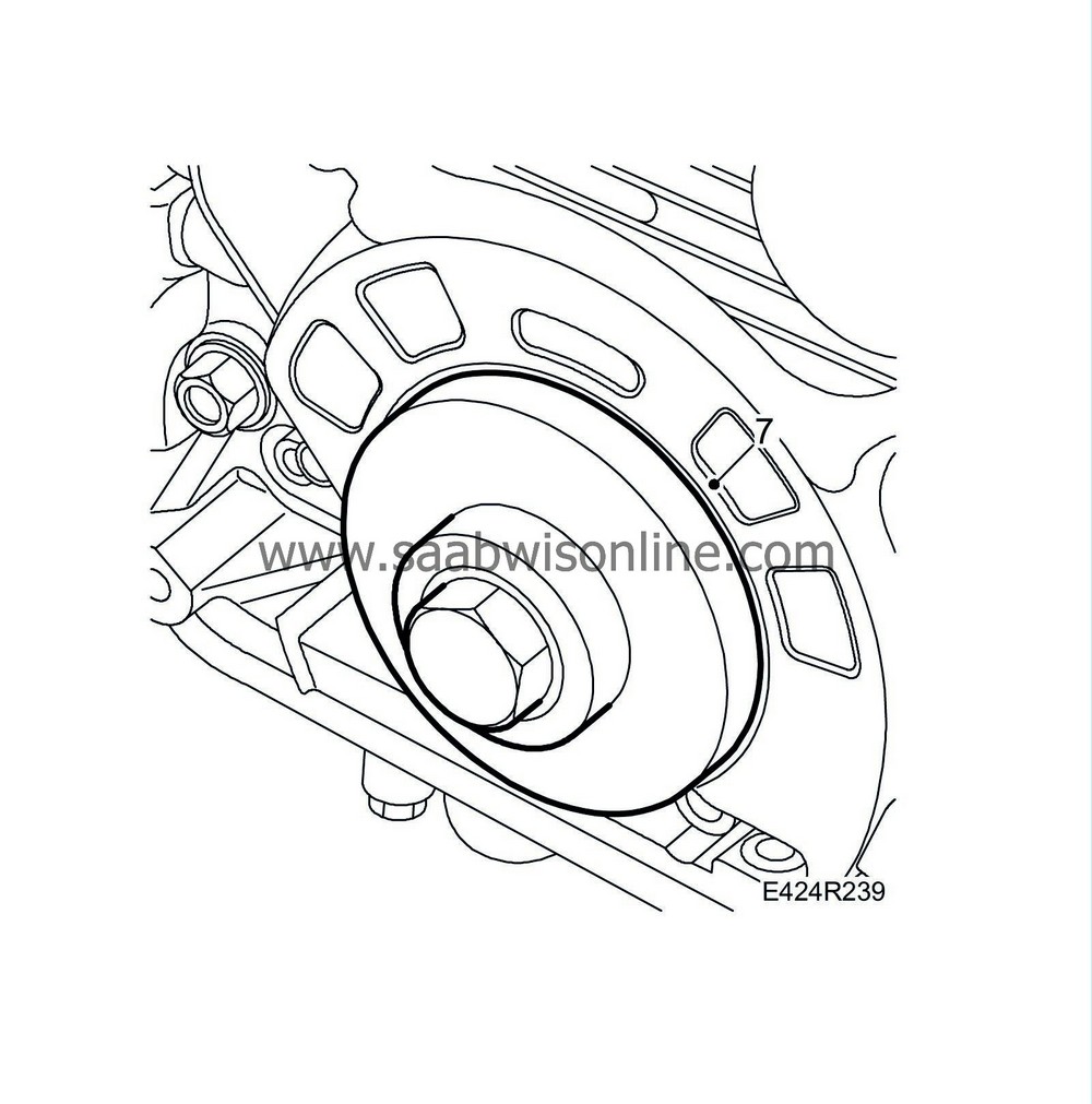
Fit the sealing ring for the crankshaft. Use
83 95 717 Fitting tool, crankshaft seal, front
.
|
|
| 8. |
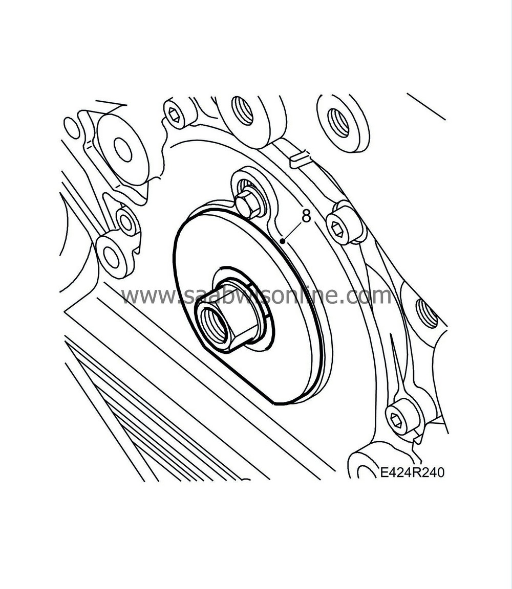
Fit a new sealing ring in the timing cover for the fuel pump. Use
83 95 758 Fitting tool, fuel pump seal
.
|
|
| 9. |
Fit the camshaft pulley on the fuel pump shaft. Make sure that the guide pin is aligned correctly. Fit the nut. Use
EN-47646 Holding tool, fuel pump
. Remove the holding tool after tightening.
Tightening torque 160 Nm (118 lbf ft) 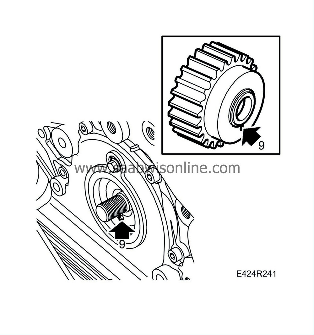
|
|
| 10. |
Remove the locking screw to the fuel pump gear and fit the plug with a new gasket in the timing cover.
|
|
| 11. |
Fit the crankshaft pulley. Do not torque tighten the bolt yet. Check that the marking corresponds against the timing cover.
|
|
| 12. |
Fit the Poly-V belt's idler pulley.
|
|
| 13. |
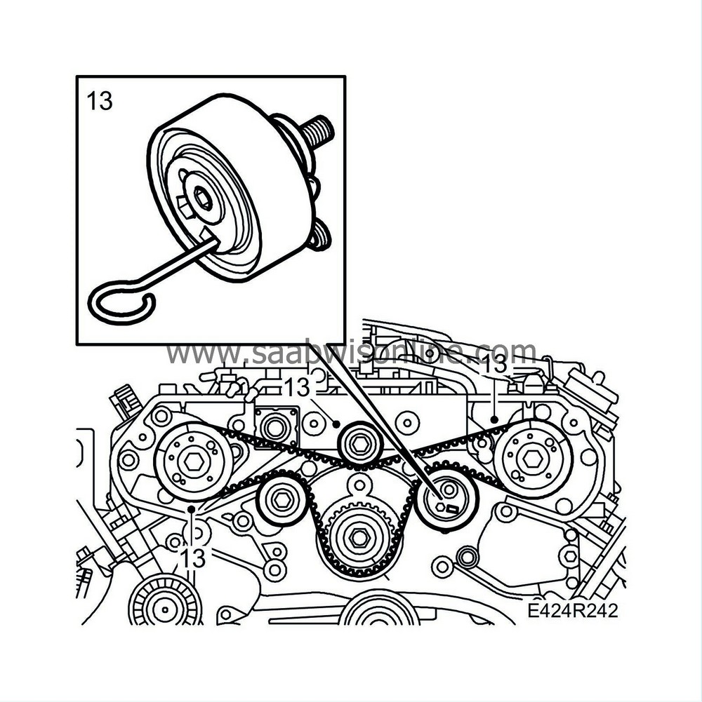
If the belt tensioner has been released, compress it using a vice and fit the locking pin. Fit the belt tensioner. Fit the belt so that the markings are aligned with those on the pulleys. Fit the idler pulleys and remove the locking pin.
|
|
| 14. |
Turn over the engine twice and check that the markings on the pulleys are aligned with those on the engine.
Camshaft pulleys' marking: LH, front cylinder bank RH, rear cylinder bank 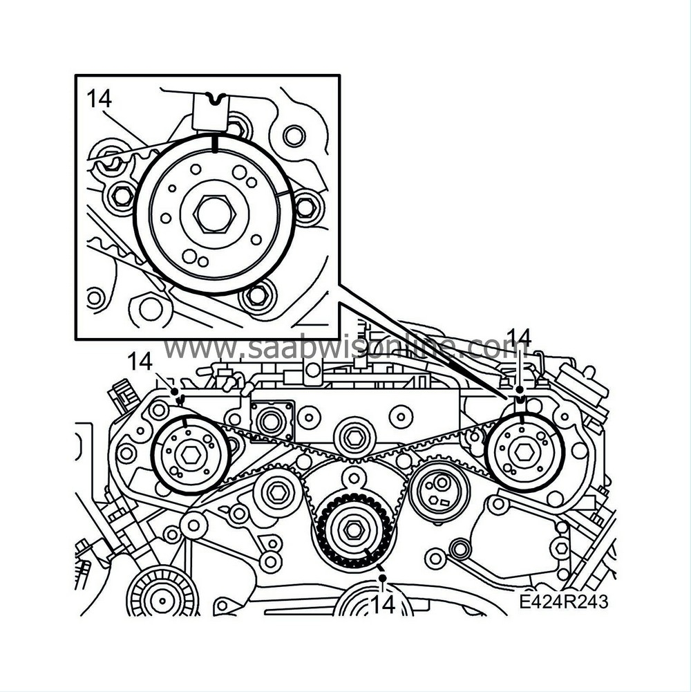
|
|
| 15. |
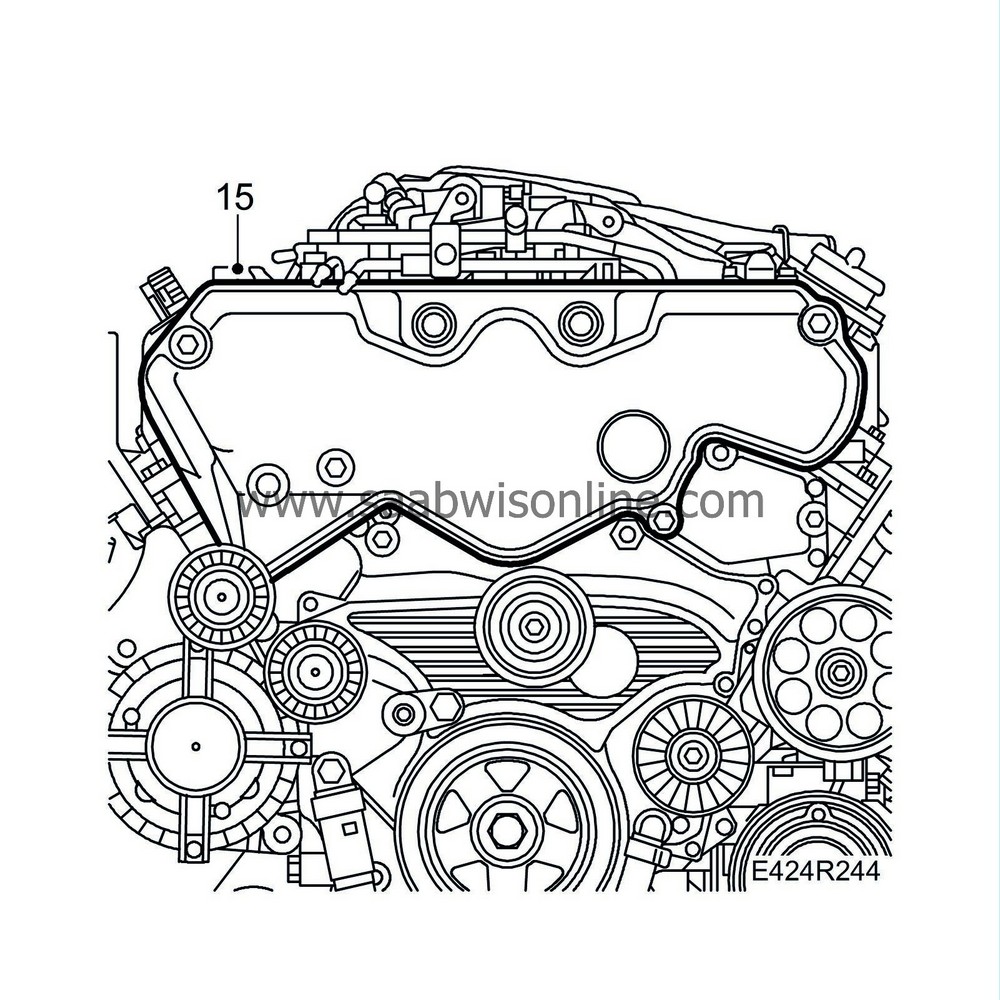
Fit the cam belt cover.
|
|
| 16. |
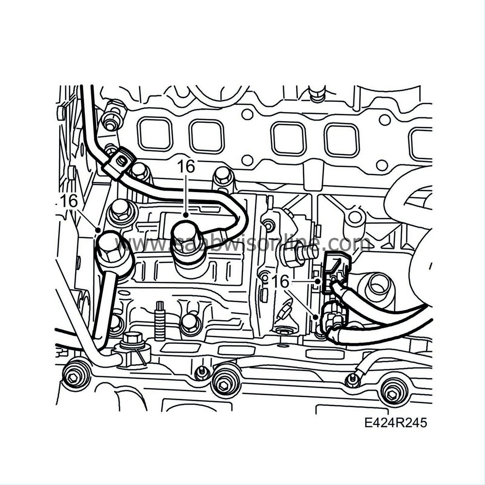
Plug in the fuel pump connectors.
|
|
| 17. |
Fit the fuel supply pipe and fuel return pipe. Use new seals.
Tightening torque, banjo bolts 20 Nm (15 lbf ft) |
|
| 18. |
Clean the sealing surfaces and fit the intake manifold with new gaskets.
Tightening torque, lower intake manifold 31 Nm (23 lbf ft) 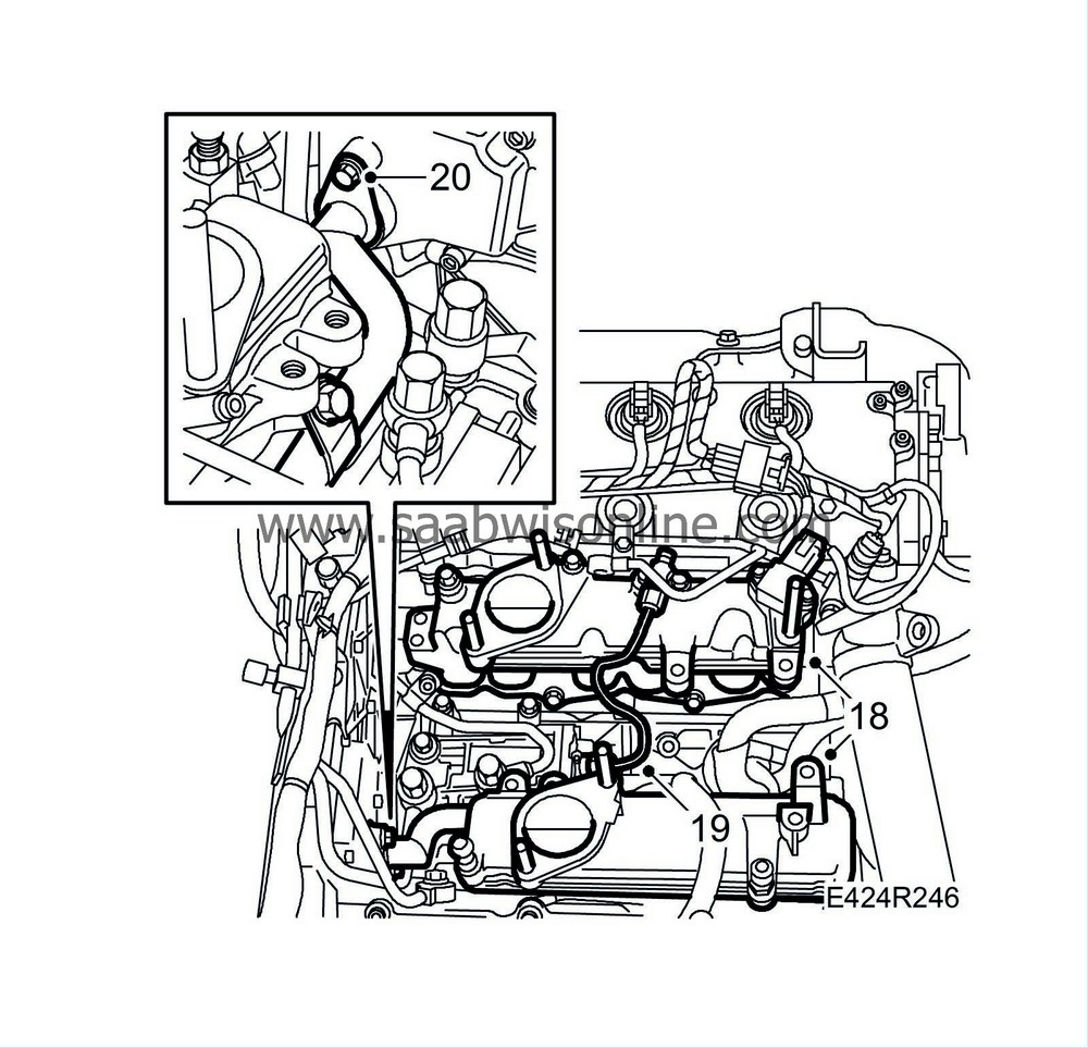
|
|
| 19. |
Fit the fuel delivery pipe.
|
|
| 20. |
Fit the crankcase ventilation pipe to the timing cover. Use a new O-ring.
|
|
| 21. |
Fit the EGR valve's water jacketed pipe with the EGR valve. Use new gaskets.

|
|
| 22. |
Fit the coolant pipe and crankcase ventilation hose.

|
|
| 23. |
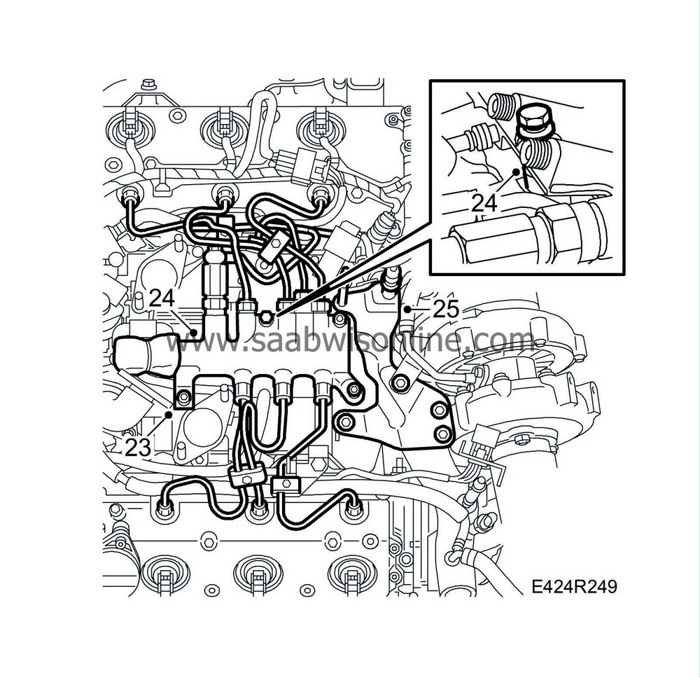
Plug in the connector to the pressure sensor and position the cables.
|
|
| 24. |
Fit the fuel rail and fuel pipes. Make sure that any spacer washers and the connector's protective sleeve are fitted correctly.
|
|
| 25. |
Fit the bracket for the turbocharger.
|
|
| 26. |
Fit the upper intake manifold with brackets and intake hose.
Tightening torque, upper intake manifold 21 Nm (15 lbf ft) 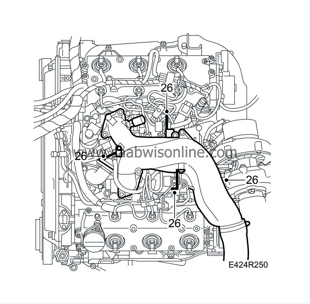
|
|
| 27. |
Fit the engine harness.

|
|
| 28. |
Raise the engine and fit the right-hand engine mounting with the upper bracket and engine pad. Remove the jack.
Tightening torque engine pad, right-hand bracket to timing cover, upper bolts 40 Nm + 90° (30 lbf ft + 90°) Tightening torque engine pad, right-hand bracket to timing cover, lower bolts 64 Nm (47 lbf ft) Tightening torque engine pad, right-hand to body 40 Nm + 30° (30 lbf ft +30 °) Tightening torque engine pad, right-hand nut 105 Nm (77 lbf ft) 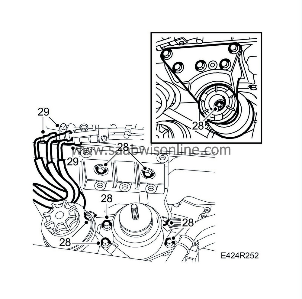
|
|
| 29. |
Fit the quick-release couplings on the fuel lines.
|
|
| 30. |
Fit the nut of the rear engine pad.
Tightening torque: 47 Nm (35 lbf ft) 
|
|
| 31. |
Fit the upper engine cover and the intake manifold between the mass air flow sensor and the turbocharger.
Tightening torque, mass air flow sensor: 3.5 Nm (2.5 lbf ft) 
|
|
| 32. |
Raise the car and fit the front bolt to the front torque arm.
Tightening torque: 90 Nm + 90° (66 lbf ft + 90°) 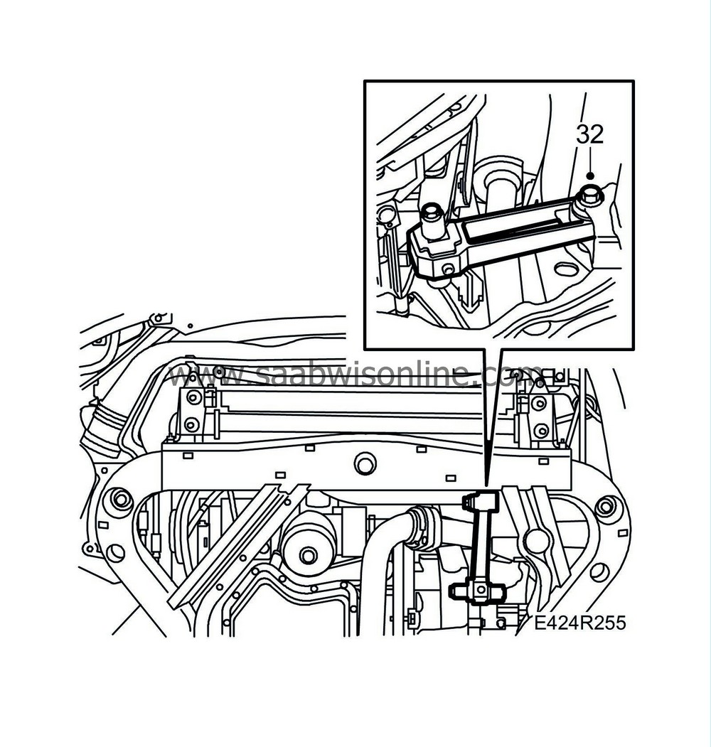
|
|
| 33. |
Torque tighten the crankshaft pulley. Use 32 025 019 Holding tool, camshaft sprocket.
Tightening torque: 235 Nm (173 lbf ft) |
|
| 34. |
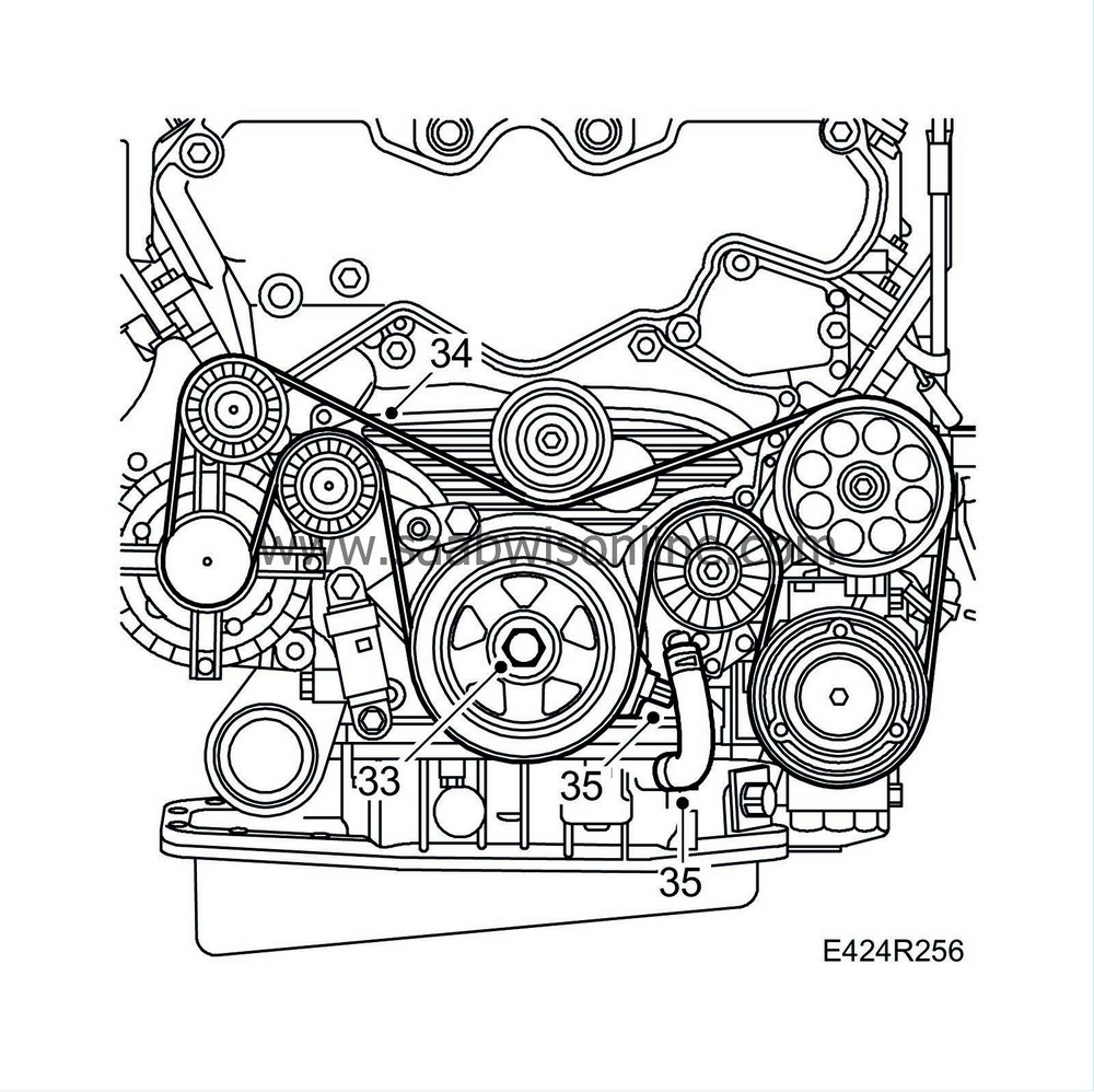
Fit the belt tensioner and multigroove V-belt
|
|
| 35. |
Connect the crankshaft position sensor and fit the oil return hose.
|
|
| 36. |
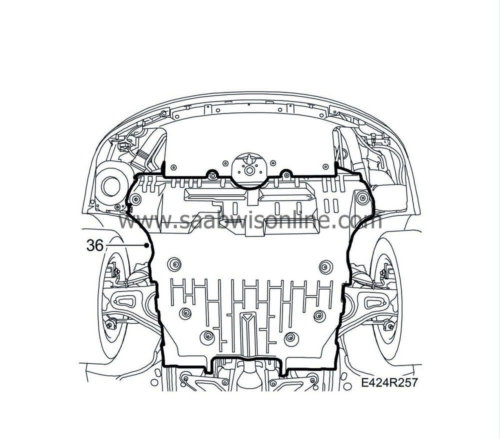
Fit the right-hand cover and the lower engine cover.
|
|
| 37. |
Lower the car. Bleed the fuel system following
Bleeding the fuel system
.
|
|

 Warning
