Description of operation, function chains
|
|
Description of operation, function chains
|
A large number of function chains can be identified in the bus system. Below are three examples of important ones.
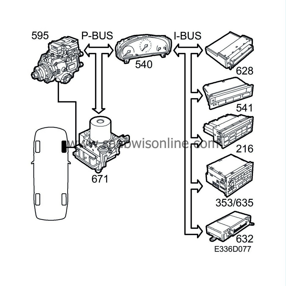
Vehicle speed is sensed by the ESP system through a proximity sensor at each wheel. The sensor supplies the control module with alternating current, the amplitude and frequency of which increase with increasing wheel speed. The frequency is proportional to wheel speed, 29 Hz at a speed of one wheel revolution per second. The ESP control module uses the 4 wheel speeds to prevent wheel lock-up on braking.
The ESP control module is connected to the P-bus and transmits the wheel speed for each of the four wheels. However, only the speed of the rear left and front right wheels are used by other systems.
Wheel speed RL:
The ESP control module transmits the bus message “Wheel speed rear left xxx km/h”. This message is used by the MIU (internal). The MIU sends “Vehicle speed” along the P-bus and I-bus.
Wheel speed FR:
The ESP control module transmits the bus message “Wheel speed front right xxx km/h”. This message is used by the engine control module.
Since the main instrument panel is connected to a bus, all control modules connected to the bus are supplied with information on the speed of the left-hand rear wheel and the odometer reading.
The table of transmitted bus messages shows that MIU transmits the vehicle speed and that it is used by: Trionic, SID, ACC, Audio and TWICE. MIU also transmits the odometer reading, which is used by SID for the service indicator.
The various systems use the vehicle speed for the following functions:
|
•
|
The PSG 16 receives information about the wheel speed of all four wheels via the bus and a separate lead from the ESP for front right wheel speed. The wheel speed signal on the separate lead is used by the cruise control function.
|
|
•
|
DICE uses the value to activate the radiator fans for A/C on, high outside temperature and low speed.
|
|
•
|
SID uses the value for trip computer functions.
|
|
•
|
ACC uses the value for activating recirculation in connection with high outside temperature and low speed.
|
|
•
|
The Audio system uses the value for increasing the volume at high speeds.
|
|
•
|
TWICE uses the value for automatic locking of the doors when driving off (certain markets).
|
Diagnosis
The ESP has extremely good diagnostics for its wheel sensors. This means that with a high degree of certainty the wheel speed signals will be present on the control module's four outputs if no diagnostic trouble codes have been generated in the system.
Neither the main instrument panel nor any of the other bus systems have speed signal diagnostics for the LH rear wheel. If the speedometer is working, however, it is certain that speed information is present on the bus and consequently available to all systems connected to the bus.
If the speedometer
does not
work, the speed on a bus is constantly 0, and there are no DTCs in the ESP, it is most likely that the ESP is missing from the bus.
The PSG 16 includes diagnostics for the speed signal from the front right wheel.
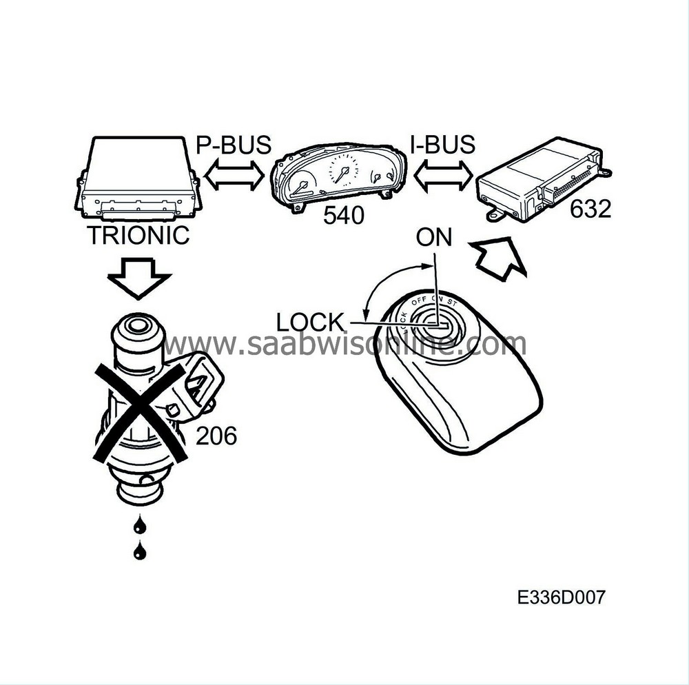
When the ignition is turned on. TWICE checks that the right key is inserted in the ignition switch. A circuit built into the remote control part of the key sends a code by means of inductance to a coil round the ignition switch under the centre console. The code is passed on to the control module which checks that it is correct. TWICE also checks that the right MIU is fitted in the car. MIU continuously sends out an ID number on the bus.
If the key and the MIU's ID number are OK, TWICE sends out the message ”Immobilization OFF” on the bus. This information is used by Trionic which cancels fuel shut-off, which is always activated every time the ignition is switched on.
Diagnosis
When TWICE, MIU or the Trionic control module is replaced, immobilization must be reprogrammed in TWICE. If this is not done, the engine cannot be started and DTC P1460 is set in Trionic.
If immobilization is not reprogrammed in TWICE, the following DTCs are set in TWICE: DTC B1780 with replacement of Trionic, DTC B1782 with replacement of MIU.
If the diagnostic trouble code is generated even though programming was carried out, fault diagnosis will have to be carried out on the immobilization function in TWICE.
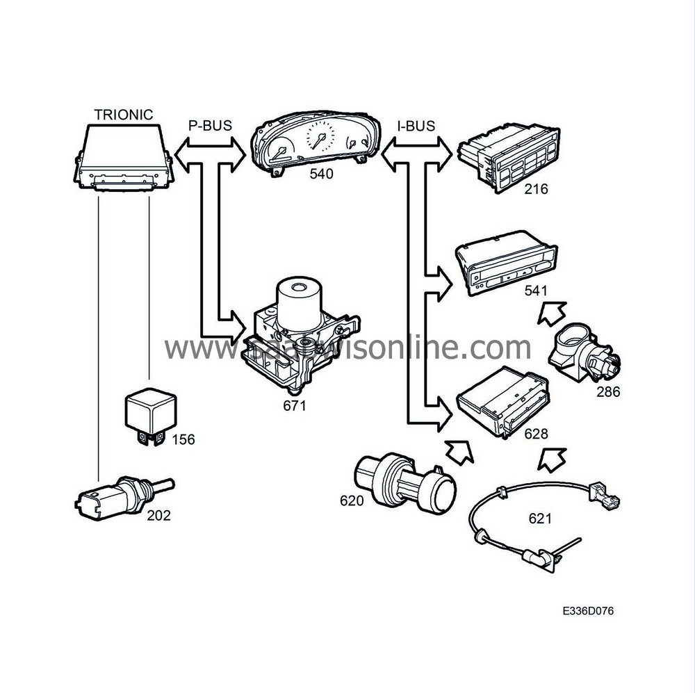
A number of conditions must be met for the A/C relay to be grounded and the A/C compressor's electromagnetic clutch to pull.
In AUTO mode the ACC unit will request A/C engagement from DICE if:
|
•
|
Outside temperature (information via bus from SID) is above 0°C.
|
DICE then requests that the TRIONIC control module ground the A/C relay if the following conditions are fulfilled:
|
1.
|
Coolant temperature (information via bus from the Trionic) is below 125°C.
|
|
2.
|
Refrigerant pressure (own sensor) on the high-pressure side is between 2 and 27 bar.
|
|
3.
|
The temperature in the evaporator (own sensor) must fulfil the following conditions:
|
|
|
3.a.
|
If the temperature in the evaporator is above 3°C, DICE sends via the bus a request to the Trionic control module for A/C engagement.
|
|
|
3.b.
|
If the temperature in the evaporator is below 0°C, the A/C compressor can only be engaged if the conditions in points 4 and 5 are satisfied.
|
|
4.
|
The outside temperature (information via bus from SID) must be above 25°C.
|
|
5.
|
One of the following conditions must also be met:
|
|
|
5.a.
|
The engine must not have been running for more than 30 minutes (information via bus from the Trionic control module).
|
|
|
5.b.
|
Vehicle speed is below 5 km/h (information via bus from MIU).
|
The Trionic will then activate the compressor relay.
Diagnosis
In the event of a fault in any of the aforementioned sensors in the systems concerned, the A/C compressor will not work. The function chain clearly shows the importance of obtaining diagnostic trouble code readouts from all systems because several systems are involved in any given function.
If there are no diagnostic trouble codes with the ”A/C not working” symptom description, all input values which can block the function must be checked methodically by means of the diagnostic tool's read value commands. The compressor relay is activated in the Trionic system. Then carry out fault diagnosis in the system which ”owns” the defective sensor or actuator.


