PRE-RELEASE
Symbols used in the wiring diagrams
| Symbols used in the wiring diagrams |
| General |
The wiring diagrams are compiled with the following preconditions:
| • |
Unless otherwise indicated, switches and relays are represented in their inactivated and unenergized state.
|
|
| • |
No key in the ignition
|
|
| • |
Central locking system unlocked
|
|
| • |
Coolant, brake and washer fluids full
|
|
| • |
Gear lever/selector lever in neutral
|
|
| • |
Parking brake released
|
|
| Fuses |
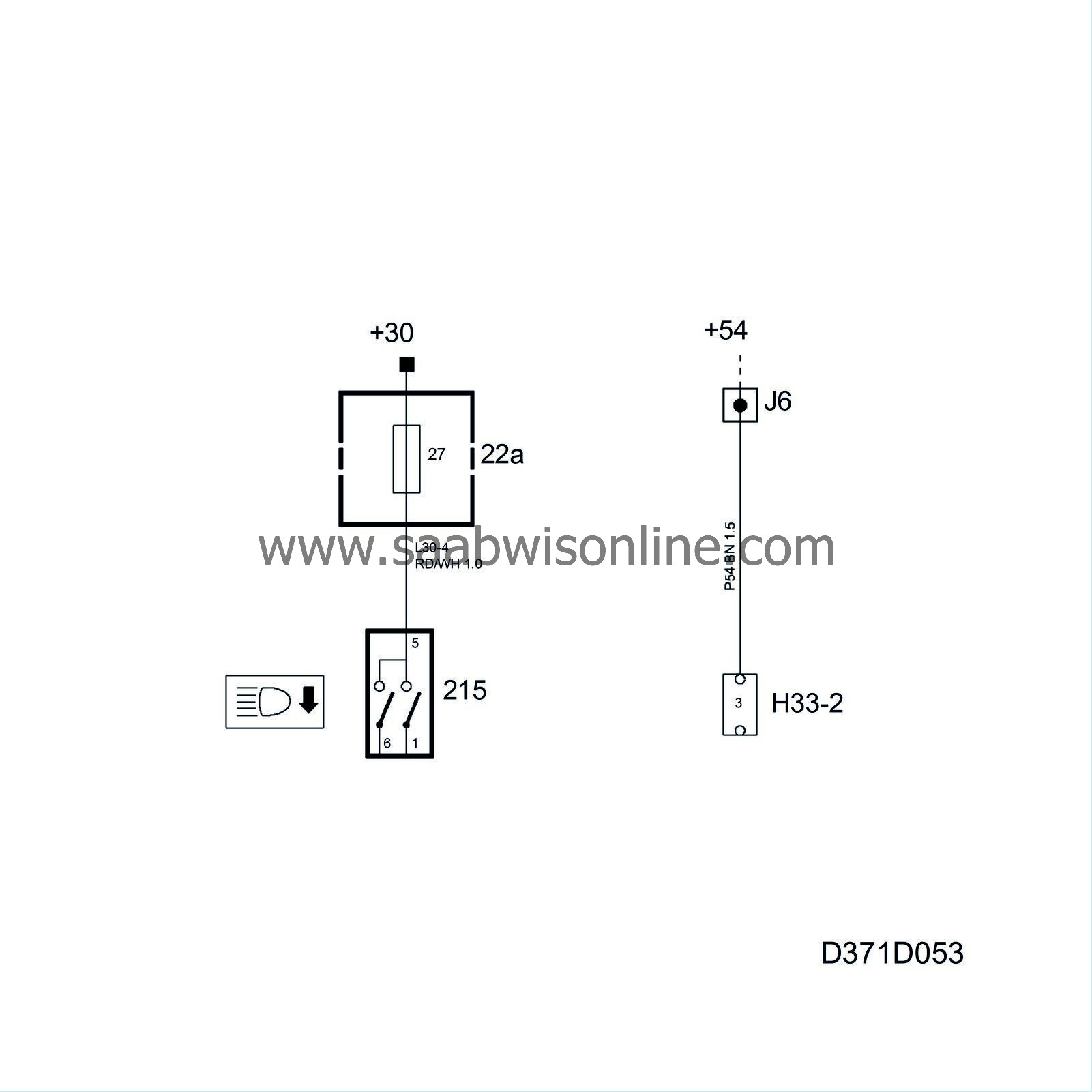
To simplify fault diagnosis, a broken line is used in certain instances to signify the power supply.
The power supply to the respective fuse is shown separately in the power supply diagram.
Example:
The supply to a fuse comes from +30. The supply to the relevant fuse can be seen in the wiring diagram "Electrical system - Cable harnesses - Wiring diagrams - Power supply +30".
| Grounding points |
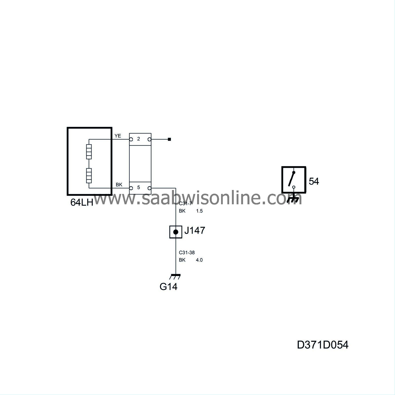
Most of the grounding points in the car have been given a component number comprising a letter and a number, e.g. G14.
Only the components connected to the system are shown in the system diagram.
In some cases, ground connections are split into a so-called signal ground and a power ground. They are given the additional letter S or P respectively. Components with low power consumption and cable screens are grounded to the signal ground connection.
The location of the grounding points and the components that are connected to each grounding point are shown in "Electrical system - Wiring harnesses - Technical Description - Grounding points" and "Electrical system - Wiring harnesses - Component locations".
Certain components are grounded directly to the body, e.g. the door switches. These ground connections are indicated by a thicker line than normal connections to the grounding point.
| Switches, relays and components |
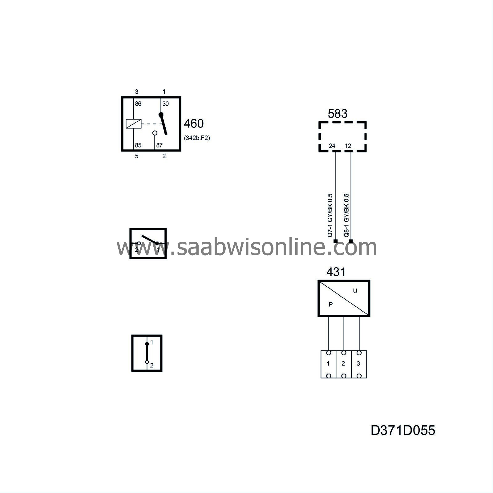
The location of the relays is given in brackets below the component number.
| Note | ||
|
Pin number 1-9 are the numbers stamped on top of the relay board, not the relay pin numbers. |
When the box around the component is drawn with a solid line, the whole component is shown.
When the box around the component is drawn with a broken line, only part of the component is shown.
On some components with hanging leads, the connector has not been given a separate H number to show that it is part of the component.
Connectors on components with more than one connector are normally specified with position numbers such as A, B. The connector pin numbers are then given as 22(A), 22(B).
The components are designated by a serial number and one or more supplementary letters that indicate their location and type. The location is indicated by capital letters, e.g. 298FL, while the type is indicated by lower case letters, e.g. 47a. The following abbreviations are used to indicate location:
|
C
|
=
C
entre
|
|
D
|
=
D
river's side
|
|
F
|
=
F
ront
|
|
H
|
=
H
atch (boot lid/tailgate)
|
|
P
|
=
P
assenger side, front
|
|
R
|
=
R
ear
|
|
LH
|
=
L
eft
H
and
|
|
RH
|
=
R
ight
H
and
|
Illustrations of all component connectors can be found in "Electrical system - Wiring harnesses - Component locations".
| Connectors |
The connectors located between the various wiring harnesses start with the letter H, e.g. H16-1, where the number after the H indicates the number of poles the connector has. The number after the hyphen is a serial number within that pole quantity group. In the example H16-1, the connector has 16 poles and it is the first in the group.
Illustrations of all connectors can be found in "Electrical system - Wiring harnesses - Component locations".
| Sensors and monitors |
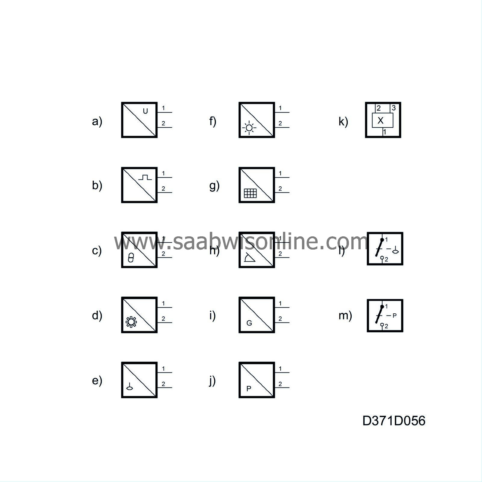
The symbols for sensors and monitors have been simplified. The connector/output side of the sensors have an internal symbol showing the type of output signal and the other half is a symbol showing the measured quantity.
All internal symbols for the measured quantity may be used with other components.
a. Sensor output with continuous voltage
b. Sensor output with pulsed voltage, e.g. frequency or PWM
The outputs are combined with the following quantity symbols to indicate the correct type of sensor:
c. Temperature
d. Speed/engine speed via toothed wheel or similar
e. Level
f. Sun
g. Load
h. Angle
i. Acceleration
j. Pressure
One type of sensor that can be used for different purposes is
k. Hall sensor
A monitor is shown as a switch with type of quantity:
l. Level switch
m. Pressure switch
| Crimped connections |
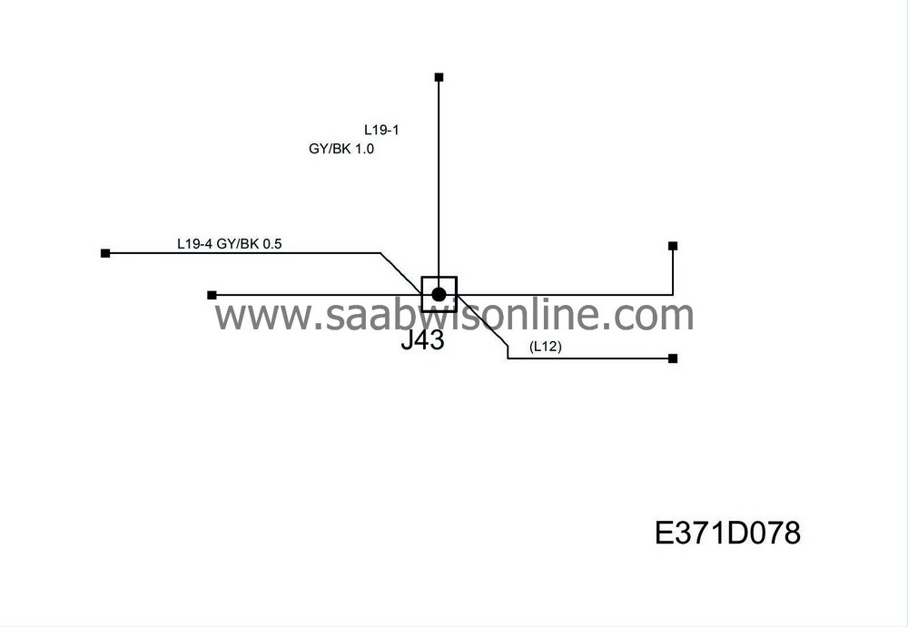
To reduce the number of connectors used in the car, several crimp connections are incorporated in the wiring.
The crimp connectors immediately above the grounding points have been ultrasonic welded for reliability.
Only the components connected to the system are shown in the system diagram.
Each crimp connection is illustrated in “Electric system - Wiring harnesses - Component locations” in a wiring diagram together with all the connected components.


