PRE-RELEASE
Main beam, xenon, other markets
| Main beam, xenon, other markets |

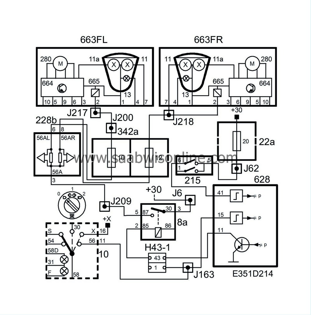
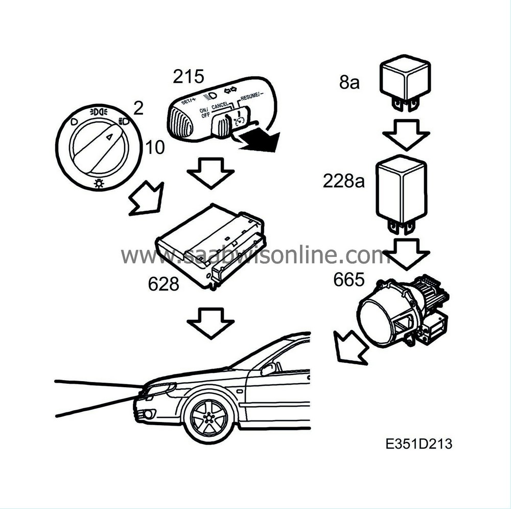
Main beam is turned on by moving the dipswitch on the steering column towards the steering wheel rim when the light switch is in position 2 and the ignition is ON. DICE activates the main beam relay (8a).
To enable DICE to determine what position (0-1-2) the light switch (10) is set to, the control module uses bus information from TWICE and its own pins 39 and 15.
TWICE monitors the parking lights and sends information on the bus (Rear light Left ON/OFF and Rear light Right ON/OFF). The ON message corresponds to switch position 1 and the OFF message corresponds to position 0 or 2.
To enable DICE to determine the position setting, it uses pins 39 and 15. DICE pin 39 is connected to light switch pin 10, which corresponds to position 0. DICE pin 15 is connected to light switch pin 11, which corresponds to position 2.
B+ voltage is supplied from connection 11 on the light switch (10) to control module pin 15. When the switch (215) is turned on, B+ voltage is fed from pin 6 to DICE pin 41. DICE lights main beam by control module pin 11 grounding pin 5 of the main beam relay (8a). When the relay is activated, B+ voltage is fed via the relay to fuse 12 and on to pin 2 of the right-hand headlamp and via pin 10 to pin 2 of the left-hand headlamp.
MIU (540) is powered from fuse 10 so that a lamp 47g on MIU comes on to indicate that the main beam is on.
| Important | ||
|
When changing a bulb, select a new bulb of the correct rating to prevent the components being damaged. |
||
| Diagnosis |
Diagnostic trouble code B2280 is generated in the event of an open circuit or a short circuit to ground in the main-beam relay circuit.
DTCs are not generated if the voltage is below 11 V and the diagnostic communication is in use.
| Headlamp flasher |


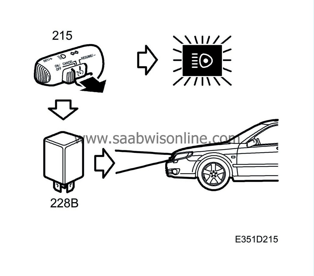
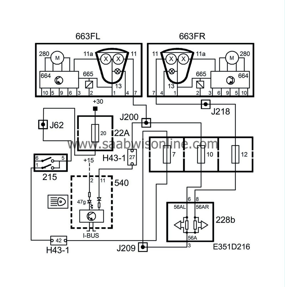
The headlamp “flasher” can be activated whatever the positions of the ignition switch and the light switch by using the dipswitch (215) to the right of the steering wheel.
The headlamp flasher turns on the halogen lamp when the lights are switched off. With the lights switched on, the halogen lamp will come on together with the xenon lamp.
When the switch (215) is moved to its “spring-back” position when the lights off, voltage will be fed to pin 2 of the headlamps (663FL/663FR) via fuse 7.
When the switch (215) is moved to its “spring-back” position with the lights on, voltage will be applied to the headlamp (663FL/663FR) pin 2 via fuse 7.
The MIU (540) receives power from fuse 10 so that a lamp on the MIU lights up to indicate that the main beam is on.
| Diagnosis |
The function has no diagnostics.


