ESP regulation and brake application
|
|
ESP regulation and brake application
|
|
1.
|
Pressure Increase Valve Front Left
|
|
2.
|
Pressure Increase Valve Front Right
|
|
3.
|
Pressure Relief Valve 1
|
|
4.
|
Pressure Relief Valve Front Right
|
|
6.
|
Brake caliper, front left
|
|
7.
|
Brake caliper, front right
|
|
8.
|
Brake caliper, rear left
|
|
9.
|
Brake caliper, rear right
|
|
10.
|
Front left inlet valve
|
|
11.
|
Front right inlet valve
|
|
12.
|
Rear left inlet valve
|
|
13.
|
Rear right inlet valve
|
|
14.
|
Front left outlet valve
|
|
15.
|
Front right outlet valve
|
|
16.
|
Rear left outlet valve
|
|
17.
|
Rear right outlet valve
|
|
19.
|
Brake pressure sensor
|
When the ESP operates, the control module starts the return pump, which then runs for the entire modulation cycle. At the same time, the pressure relief valve is shut to allow a build-up of pressure. The pressure increase valve is opened to supply the pump with brake fluid.
The control module closes the pressure increase valve when a preset pressure is reached. The pressure is then regulated by
|
•
|
opening the pressure increase valve to increase the pressure
|
|
•
|
closing the pressure increase valve and pressure relief valve for pressure holding.
|
|
•
|
opening the pressure relief valve to lower the pressure
|
Each wheel is controlled by closing the inlet and outlet valves for that wheel. Excess brake fluid that causes the pressure relief valve to open is returned to the master cylinder.
The pressure increase valve on the wheel which is spinning will open. This causes an increase in the pressure to the wheel cylinder and the wheel is braked.
|
-
|
Dashed = change of pressure
|
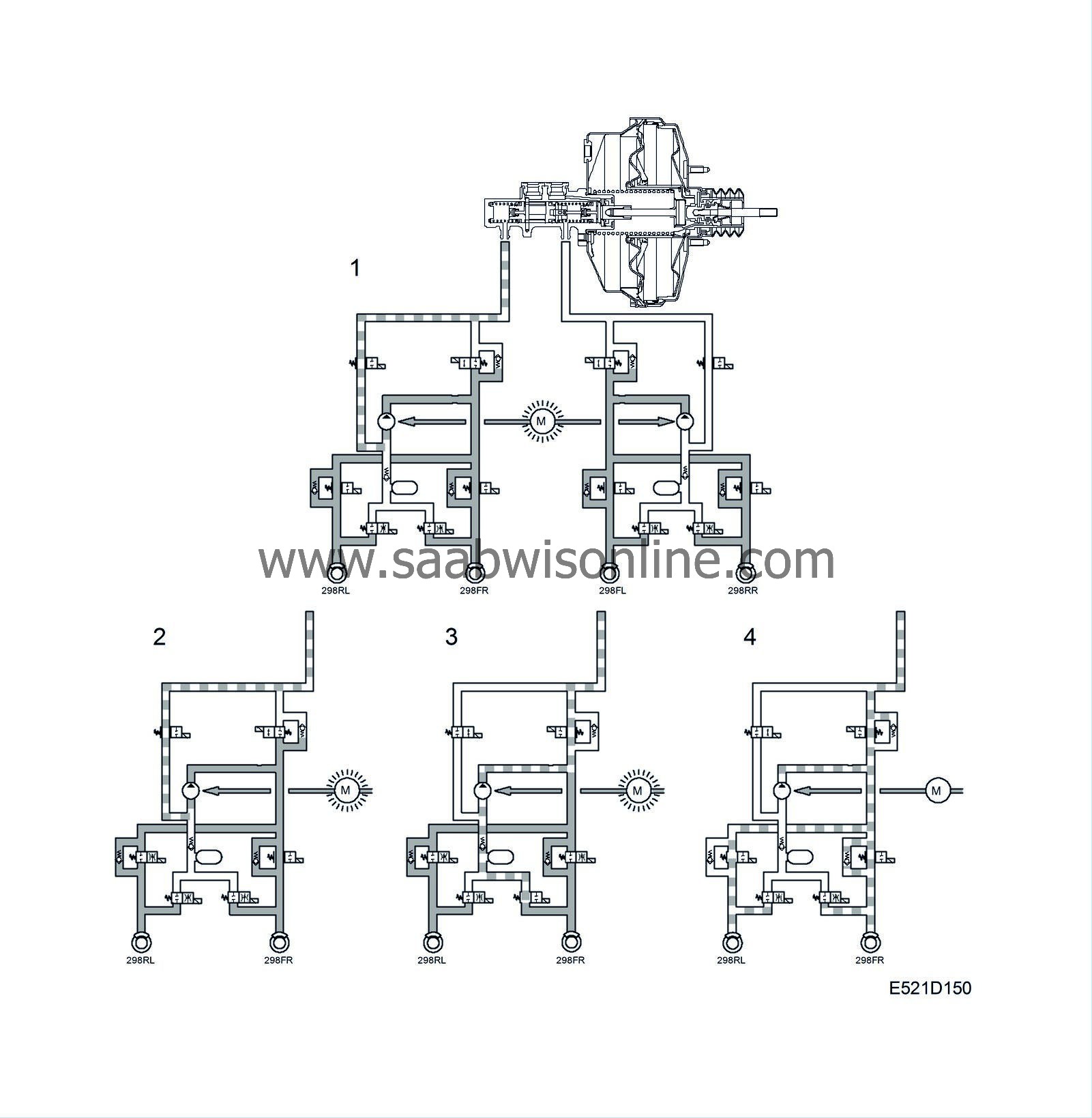
Phase 4 Release
The conditions for ESP regulation have ceased and all valves return to rest.
|
•
|
pressure relief valves are open
|
|
•
|
pressure increase valves are closed
|
|
•
|
Outlet valves are closed
|
|
•
|
return pump is switched off
|
Phase 1 Pressure build-up for all four wheels (filling pulse and maintenance of pressure). Driver not braking.
Filling pulse
At the start of modulation, a filling pulse is produced. This means that the pressure in all wheel cylinders is raised slightly (equal for all four wheels), irrespective of on which wheel the brakes are to be applied. The pump starts, the pressure relief valve closes and the pressure increase valve opens (set time).
The inlet and outlet valves are in their normal position in the valve block, i.e. the inlet valves are open and the outlet valves are closed.
Maintenance of pressure
Once the filling pulse has stopped, the inlet valves close to prepare for individual regulation on each wheel.
Wheels on which the ESP system is not going to apply the brakes: The pressure will be maintained with the pressure increase and pressure relief valves on each circuit being shut, as well as the inlet and outlet valves by each wheel. This is so that the system is ready in case braking is required.
Phase 2 Pressure increase on wheels under ESP regulation
The pressure increase valve opens to supply the pump with brake fluid that is to be pumped into the circuit. The pressure relief valve is closed.
The inlet valve on the wheel having its brakes applied will be open until the conditions that apply for pressure build up have been attained.
This means that the pressure to the wheel cylinders also increases and the wheel brake is applied. The pump is running.
Phase 3 Pressure reduction on wheels under ESP regulation
The pressure increase valve is closed and the pressure relief valve opens to lower the pressure in the circuit.
The inlet valve is closed and the outlet valve opens to lower the pressure at the wheels.
Brake fluid is returned from the wheel outlet valve through the pressure relief valve to the master cylinder. The pump is running.
Driver applying the brakes, see phases 1-3
If the driver applies the brakes while ESP regulation is active, the brake pressure sensor will inform the control module of the input brake pressure in the hydraulic unit. With this information, the brake pressure to the wheels not under ESP regulation can be controlled to correspond to the driver's braking force.
The wheel under ESP regulation when the brakes are applied is controlled according to the ESP criteria.
Phase 4. Termination
The criteria for ESP regulation have ceased to apply. All the valves take their normal positions, i.e. the pressure relief valves are open, the pressure increase valves are closed, the inlet valves are open and the outlet valves are closed. The pump stops.
Modulation continues until
|
•
|
the wheel/wheels are below limits for ESP regulation.
|
|
•
|
the ESP control module halts regulation due to a risk of the brakes overheating.
|
After regulation is terminated, the control module will stop the pump, close the pressure increase valve and open the pressure relief valve. The valves and the pump return to their normal states.
A termination of regulation with brake application due to the risk of overheating the brakes is achieved by the ESP control module continuously registering the total time that regulation with brake application has been active during a certain period of time.
This value is then compared to a programmed maximum value. If this value is exceeded, regulation with brake application will be terminated.


