Crankshaft and pistons, fitting
|
|
Crankshaft and pistons, fitting
|
|
1.
|
Clean the removed parts and blow the oil ducts clean with compressed air.
|
|
2.
|
Clean the bolt holes in the cylinder block.
|
|
3.
|
Clean away any gasket residue from the sealing surfaces of the cylinder head and cylinder block.
|
|
4.
|
Check that there are no cracks or grooves in the cylinder block.
|
|
5.
|
Check that cylinder block flatness is within the recommend interval. If not, the block must be planed.
Permissible deviation from flatness
|
mm
|
< 0.1
|
|
|
6.
|
Measure the diameter of the cylinder liners to ensure they are within the following interval.
Cylinder bore
|
mm
|
Category B
|
82.010 - 82.020
|
|
|
mm
|
Category C
|
82.020 - 82.030
|
|
|
mm
|
Class A
|
82.000 - 82.010
|
|
|
7.
|
Check that taper does not exceed the values in the table.
|
|
8.
|
Check that ovality does not exceed the recommended value.
Permitted ovality
|
mm
|
0.05
|
|
|
9.
|
If the values exceed the recommended values, the cylinder bores must be drilled to the nearest oversize.
|
Note
|
|
If drilling is necessary, all cylinder bores must be drilled.
|
Cylinder liner oversize
|
mm
|
0.1
|
|
|
10.
|
Temporarily fit the main bearing caps.
|
Note
|
|
Bearing caps are to be fitted in increasing cylinder number from 0 to 4 starting at the front edge of the engine.
|
|
|
11.
|
Tighten the bearing cap bolts. Use a disc for angle tightening.
Tightening torque: 25 Nm + 100° (18 lbf ft +100°)
|
|
12.
|
Check that the diameter of the bearing seats are within the recommended interval.
Crankshaft bearing seat diameter
|
mm
|
63.705 - 63.718
|
|
|
13.
|
Check that the crankshaft lubrication channels are free of contaminants.
|
|
14.
|
Check that the main bearing journal diameters are within the recommended interval:
Main bearing journal diameter
|
mm
|
Category B
|
59.988 - 59.994
|
|
|
mm
|
Category C
|
59.982 - 59.988
|
|
|
mm
|
Class A
|
59.994 - 60.000
|
|
|
15.
|
If the main bearing journal diameters are not within the recommended interval, they must be ground down to the next undersize.
Main bearing journal, rec. undersize
|
mm
|
0.127
|
|
Note
|
|
Undersizes for main bearings that lie outside of the above recommendations negatively affect the crankshaft's structural integrity. If grinding requires undersize of more than 0.127 mm, the crankshaft must be replaced even through there are bearing shells for undersize of more than 0.127.
|
|
|
16.
|
Check that the big-end bearing journal diameters are within the recommended interval.
Big-end bearing journal diameter
|
mm
|
Category B
|
50.793 - 50.799
|
|
|
mm
|
Category C
|
50.787 - 50.793
|
|
|
mm
|
Class A
|
50.799 - 50.805
|
|
|
17.
|
If the big-end bearing journal diameters are not within the recommended interval, they must be ground down to the next undersize.
Big-end bearing journal, rec. undersize
|
mm
|
0.127
|
|
Note
|
|
Undersizes for big-end bearings that lie outside of the above recommendations negatively affect the crankshaft's structural integrity. If grinding requires undersize of more than 0.127 mm, the crankshaft must be replaced even through there are bearing shells for undersize of more than 0.127.
|
|
|
18.
|
Check the big-end bearings. They must be replaced if there are signs of scratches of other damage. Note whether the crankshaft has been ground. Fit the new bearing shells with oversize to restore original tolerances.
|
|
19.
|
Remove the circlips and press out the gudgeon pin.
|
|
20.
|
Check the inside diameter of the connecting rod piston end. If the value is outside of the recommended interval, replace the worn bearing bushing.
Inside diameter, piston end's bearing bushing
|
mm
|
26.006 - 26.014
|
|
|
21.
|
Check that the piston bearing diameters are within the recommended interval. If the value is outside of the recommended interval, replace the piston complete with piston rings, gudgeon pin and bushings.
Inside diameter, piston bearing
|
mm
|
25.999 - 26.004
|
|
|
22.
|
Check that the outside diameter of the gudgeon pins are within the recommended interval. If the value is outside of the recommended interval, replace the gudgeon pins.
Outside diameter, gudgeon pins
|
mm
|
25.982 - 25.987
|
|
|
23.
|
Insert each piston ring and oil scraper ring in the cylinder liner and measure the ring openings. If they are not within the recommended interval, replace the piston rings/oil scraper rings.
Piston ring opening
|
mm
|
0.20 - 0.35
|
Oil scraper ring opening
|
mm
|
0.25 - 0.50
|
|
|
24.
|
Check that the outside diameter of the pistons are within the recommended interval. If the value is outside of the recommended interval, replace the pistons complete with rings and gudgeon pin.
Piston outside diameter
|
mm
|
Category B
|
81.930 - 81.940
|
|
|
mm
|
Category A
|
81.920 - 81.930
|
|
|
mm
|
Category C
|
81.940 - 81.950
|
|
Note
|
|
Measurements are to be taken at a right angle to the gudgeon pin, 9 mm from the bottom edge of the piston.
|
|
|
25.
|
Check that the clearance between the compression rings and the groove in the piston is within the recommended interval.
Compression ring clearance in groove
|
mm
|
0.050 -0.090
|
|
|
26.
|
Check that the clearance between the oil scraper ring and the groove in the piston is within the recommended interval.
Oil scraper ring clearance in groove
|
mm
|
0.030 - 0.070
|
|
|
27.
|
Fit the big-end bearing caps and check that the measurement is at the recommended value.
Tightening torque: 25 Nm +60° (18 lbf ft +60°)
Big-end bearing inside diameter
|
mm
|
53.897 - 53.909
|
If the measurement is outside of the recommended interval, replace the connecting rods.
|
|
28.
|
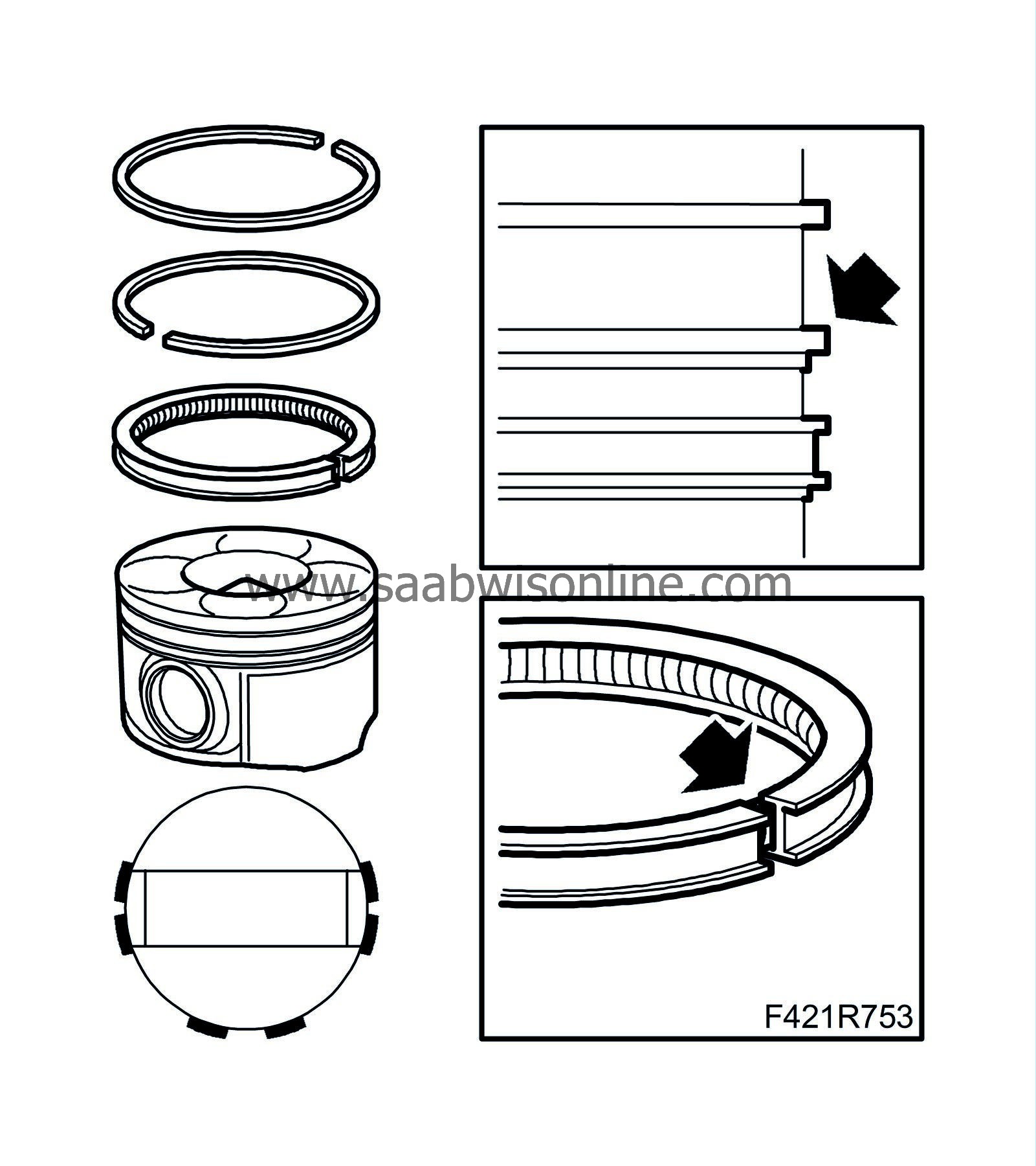
Fit the gudgeon pin, circlips and piston rings. The recess for the piston cooling nozzles should face the same direction as the connection rod marking.
|
|
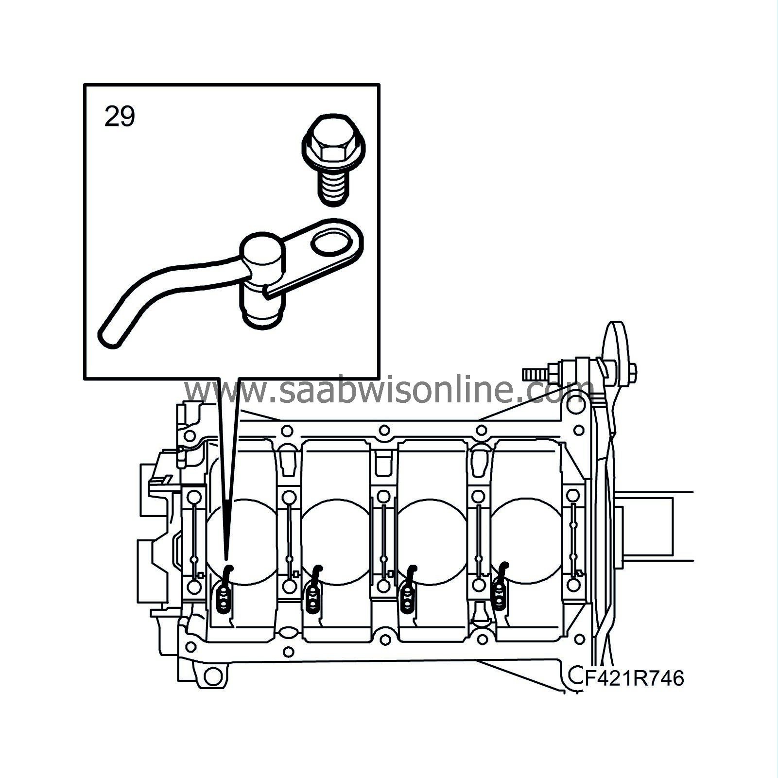
29.
|
Fit the piston cooling nozzles.
|
|
30.
|
Oil in surfaces that are to be fitted together using engine oil.
|
|
31.
|
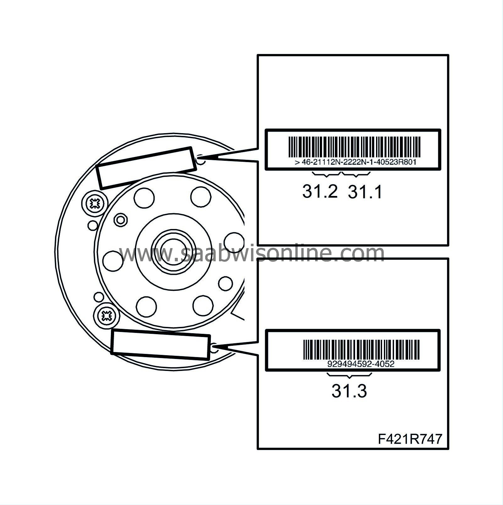
In order to select the correct bearing shells, you need the code number stamped on the slotted ring and the colour marking (if such exists) next to the crankshaft journal. The following example shows how to determine the crankshaft journal classification.
|
|
|
31.1.
|
Identification of class for big-end bearing journal: The digit on the left side refers to the first bearing on the timing side. The letter "N" at the end is of no significance for 4-cylinder engines.
|
|
|
31.2.
|
Identification of class for main bearing journal: The first digit on the left side refers to the first big-end bearing on the timing side. The letter "N" at the end is of no significance for 4-cylinder engines.
|
|
|
31.3.
|
The number series (if present) with groups of two digits indicates the sizes (in thousandths) of the main bearing journals. The first two digits to the left refer to the first big-end bearing on the timing side.
|
Note
|
|
Only the digits in the above marking should be used. The other numerical code on the flywheel is not to be used.
|
|
|
32.
|
Identification of crankshaft bearings is done as follows:
|
|
|
32.1.
|
To identify the main bearing journal classification, see the numerical code as described in 31.2. If the digits are similar to the example 11111N, all five bearings are of grade A (red colour marking).
|
|
|
32.2.
|
One way of identifying bearing grade is to read the reference number (if present) as described in 31.3. In the example in the illustration, the number 94 (the first to the left) indicates that the size of first bearing on the timing side is 52.994, which is grade A (red colour marking). The same method applies for other groups of two digits (97-95-95-94).
|
|
|
32.3.
|
Main bearing identification is done as follows:
Grade
|
Diameter
|
Colour marking
|
Code number
|
A (normal)
|
52.994 53.000
|
Red
|
1 (94 00)*
|
B (normal)
|
59.988 59.994
|
Blue
|
2 (88 94)*
|
C (normal)
|
52.982 52.988
|
Yellow
|
3 (82 88)*
|
D (0.127 mm undersize)
|
59.867 59.873
|
Brown
|
6 (67 73)*
|
E (0.127 mm undersize)
|
59.861 59.863
|
Green
|
7 (61 67)*
|
F (0.127 mm undersize)
|
52.855 52.861
|
Black
|
8 (55 61)*
|
* The last two digits indicate the last thousandths of the sizes
|
|
|
32.4.
|
If a crankshaft is used in which the maximum bearing size has become 0.127 mm due to grinding, the grade is chosen from the above table after measuring the bearing diameters. Once the grade and colour is determined for each new or ground crankshaft bearing, it is necessary to order the corresponding bearing shells with colour marking based on the table. The table's recommendations are intended to achieve optimal bearing clearance for the best function. It is important to know that the clearance between the crankshaft and bearing shells as determined following the above measurements is to lie within the interval min 0.011 mm and max 0.071 mm. This can be measured using a plastigauge as a final check.
|
|
33.
|
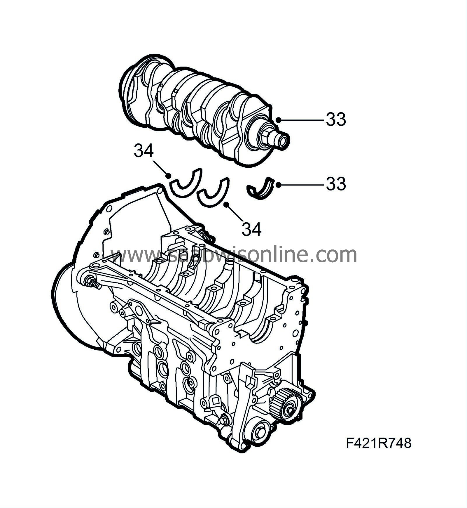
Position the upper bearing shells in their seats with the holes facing the oil ducts. Lubricate with engine oil. Insert the crankcase.
|
Note
|
|
Bearing caps have increasing numbering from 0 to 4 starting at the engine's timing side.
|
|
|
34.
|
Fix the thrust bearings in the third main bearing housing. Select the right size based on crankshaft axial clearance. The grooves on the bearings should face the crankshaft bearing surface.
|
|
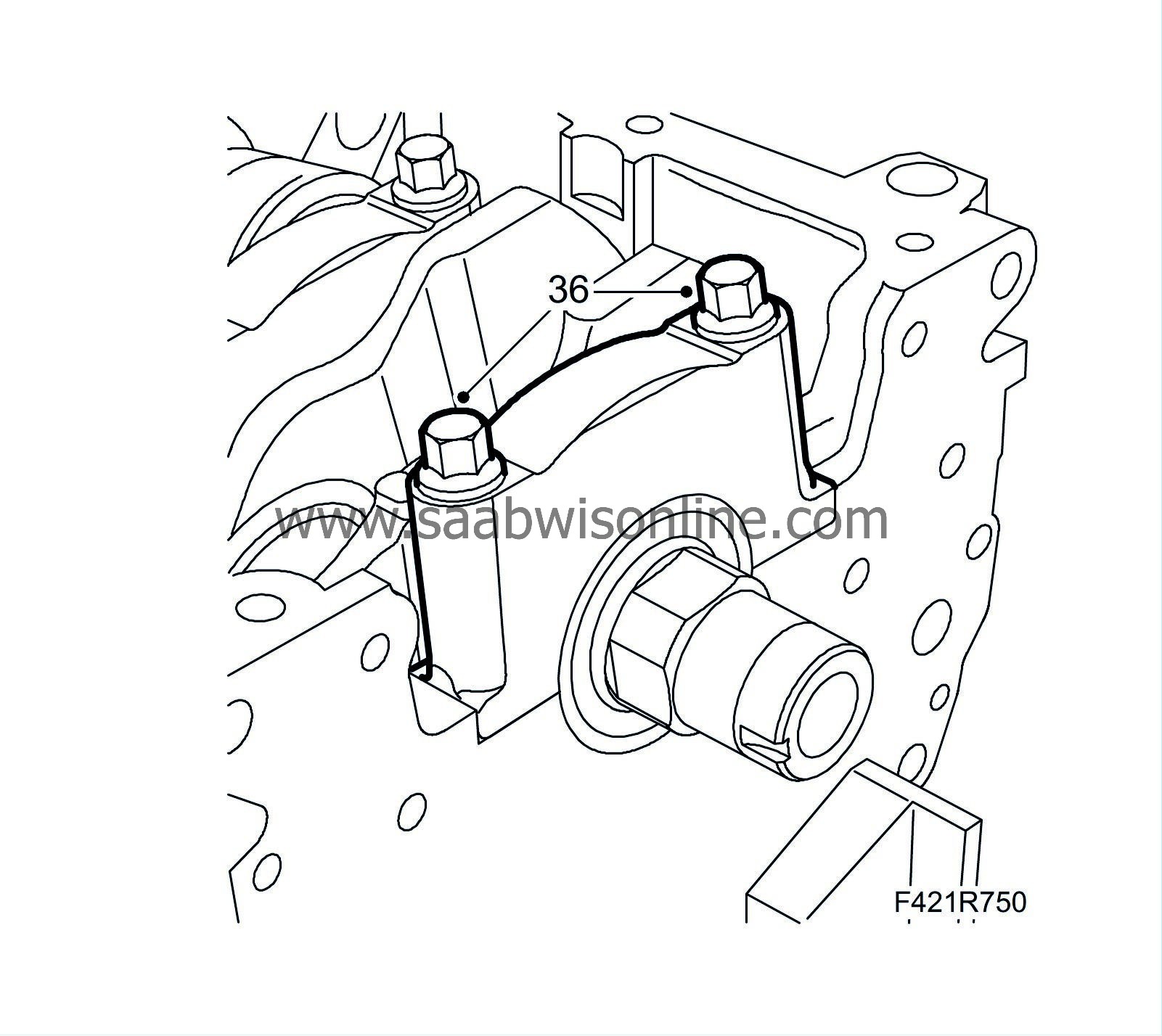
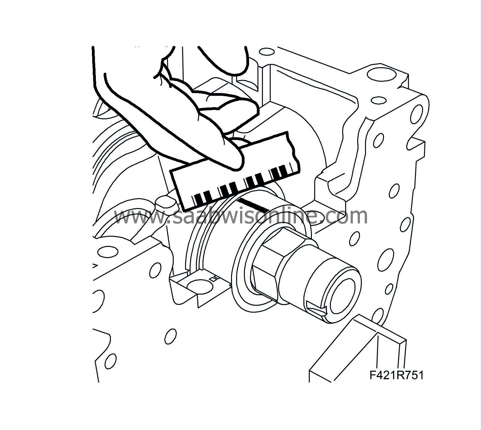
35.
|
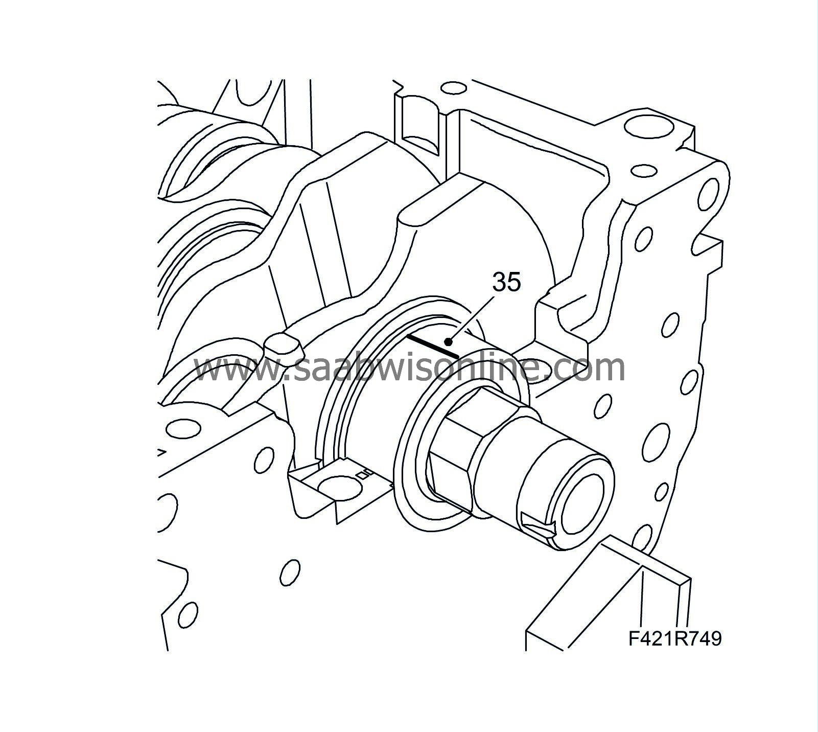
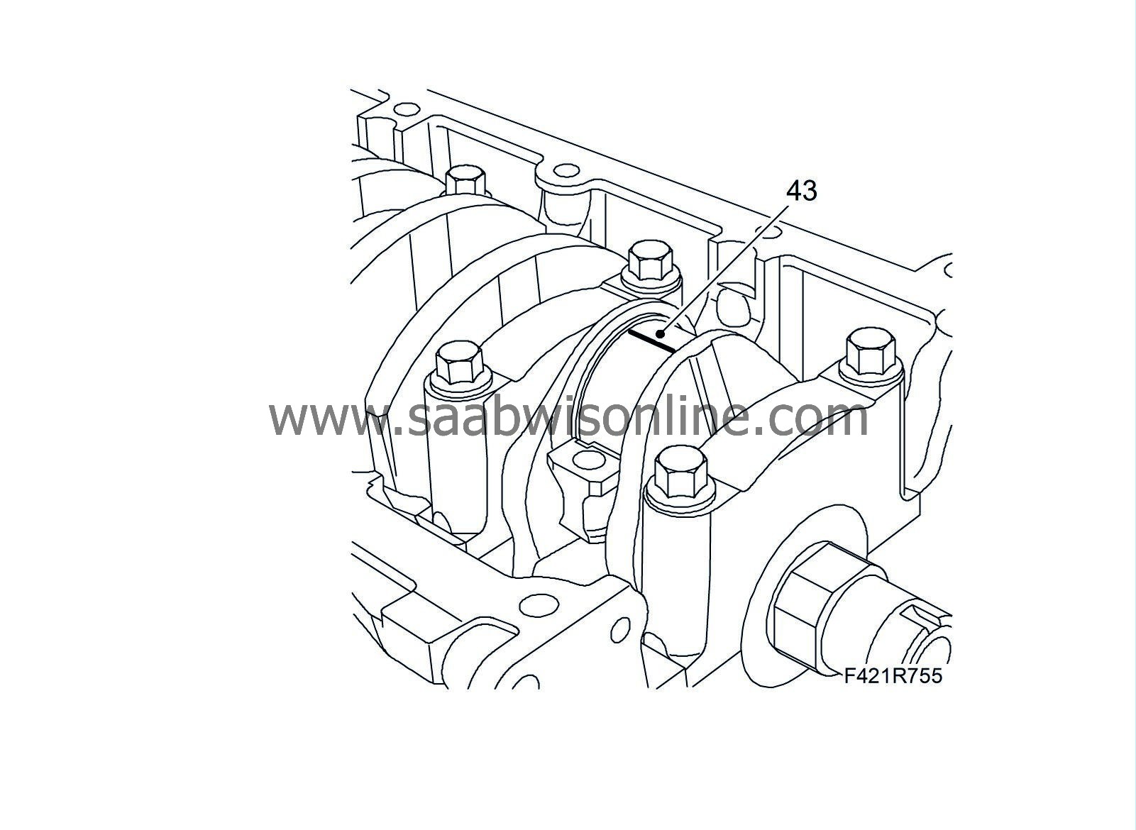
Position the plastigauge as illustrated to measure bearing clearance.
|
Note
|
|
Check on main bearing journal at a time without rotating the crankshaft.
|
|
|
36.
|
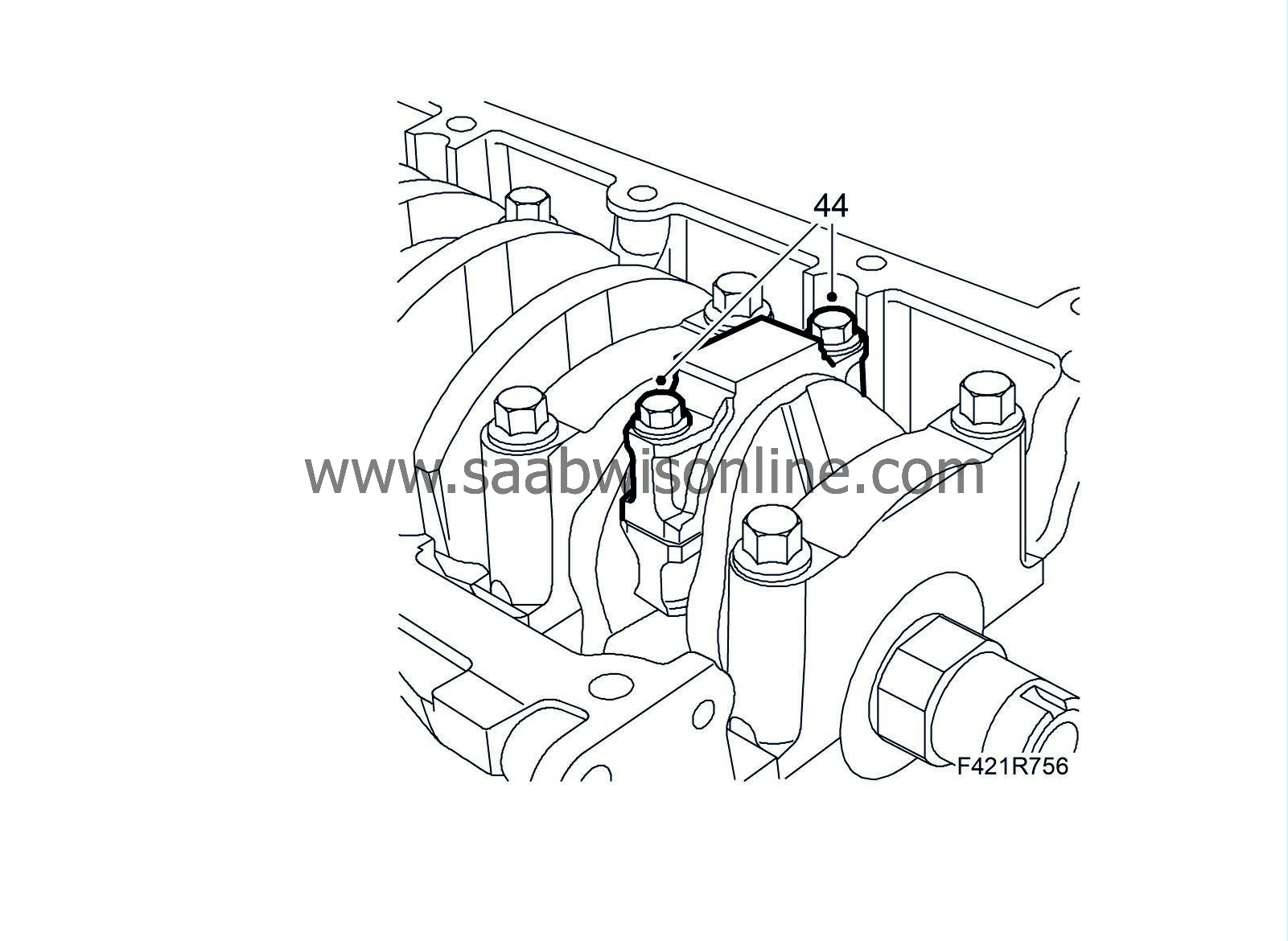
Fit the crankshaft main bearing caps complete with bearing shells.
Tightening torque: 25 Nm +100°(18 lbf ft +100°)
|
|
37.
|
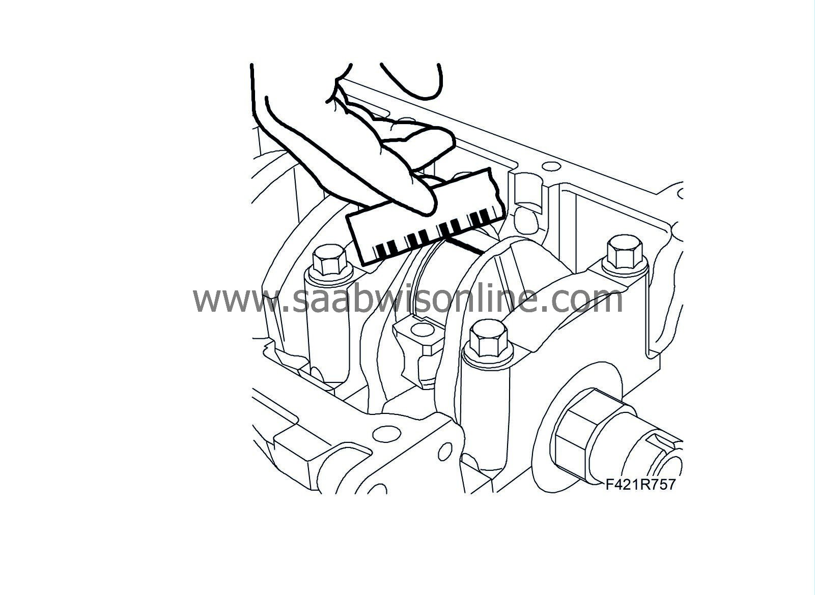
Remove the newly fitted main bearing caps and measure the clearance via the calibrated thread.
Clearance between big-end bearing and journals
|
mm
|
0.011 - 0.071
|
If the measurement does not fall within the recommended interval, replace the bearing shells with those of a suitable category and size.
|
|
38.
|
Continue measuring all bearings one at a time without rotating the crankshaft.
|
|
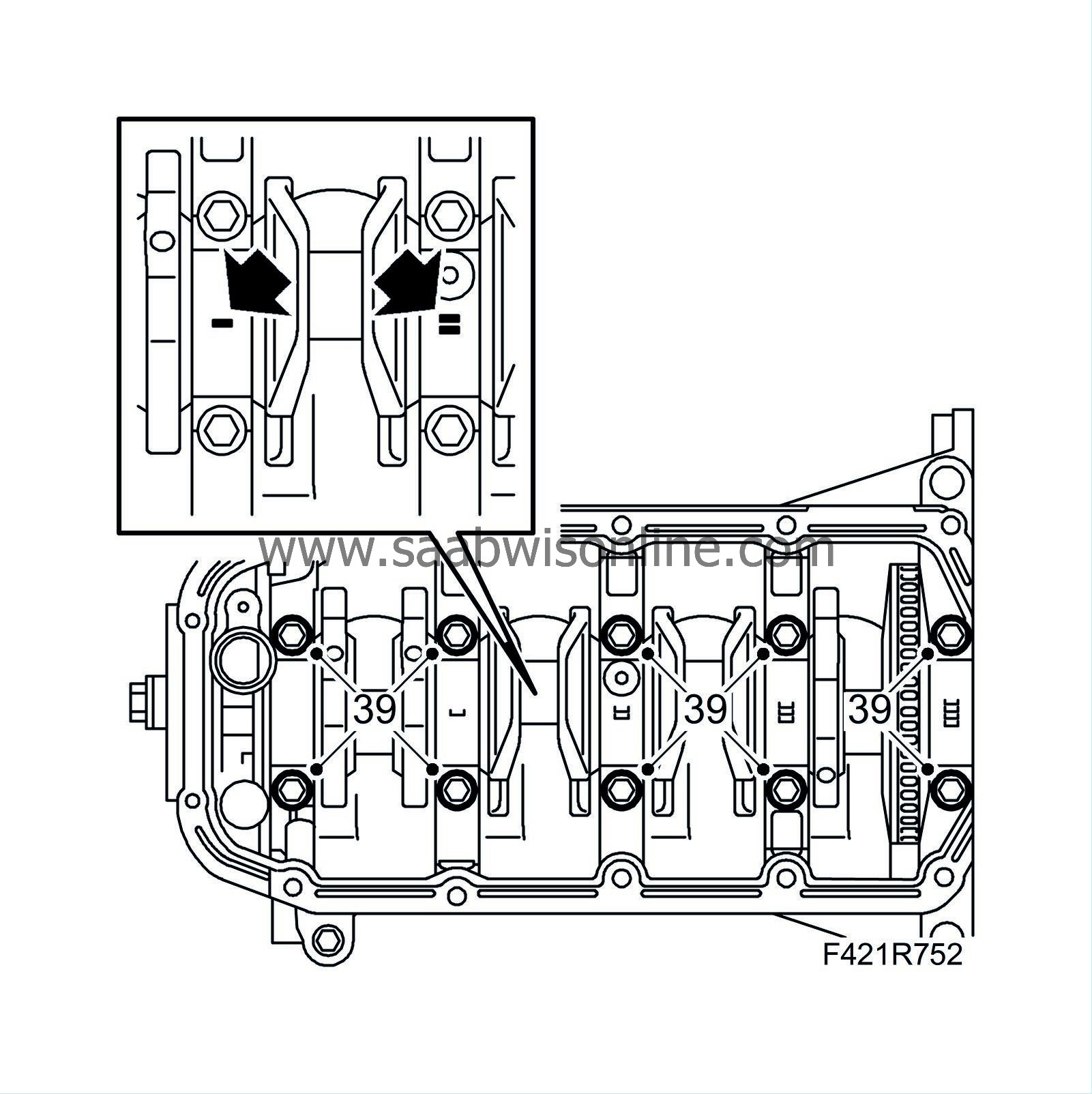
39.
|
After measuring, lubricate the bearings and fit the main bearing caps.
Tightening torque: 25 Nm +100° (18 lbf ft +100°)
|
|
40.
|
Position the piston rings as illustrated. The piston ring gaps should be spaced 120° from one another.
|
|
41.
|
Lubricate the cylinder bore and piston with engine oil.
|
|
43.
|
Position the plastigauge as illustrated to measure bearing clearance.
|
|
44.
|
Fit the bearing caps. The marking on the bearing caps should face the marking on the connecting rod.
Tightening torque: 25 Nm +60° (18 lbf ft + 60 °)
|
|
45.
|
Remove the newly fitted big-end bearing caps and measure the clearance via the calibrated thread.
Clearance between big-end bearings and big-end bearing journals
|
mm
|
0.016 - 0.070
|
If the measured value does not fall within the recommended interval, replace the bearing shells.
|
|
46.
|
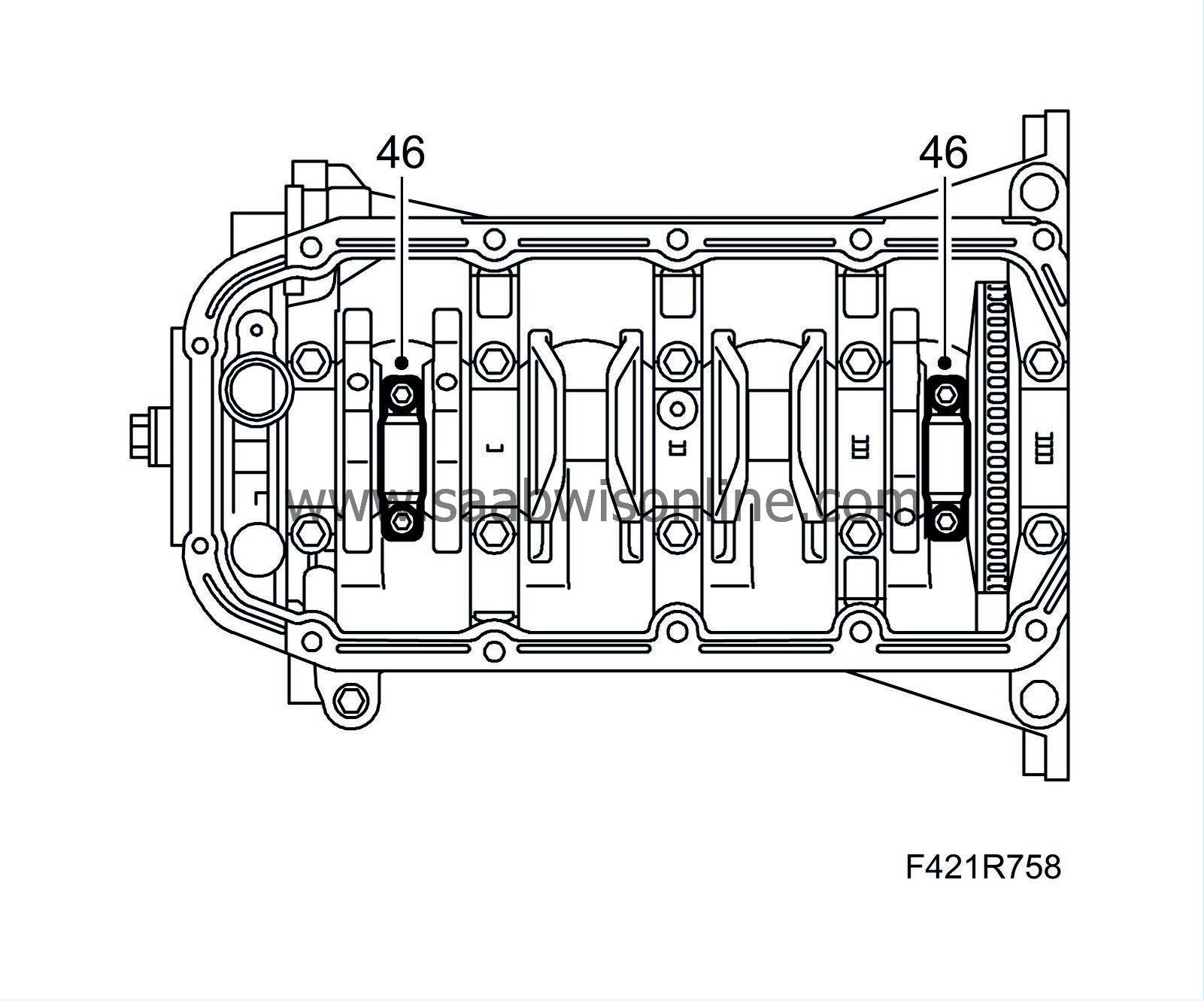
Refit the big-end bearing caps complete with bearing shells in cylinder 1 and 4. Lubricate with engine oil.
Tightening torque: 25 Nm +60° (18 lbf ft +60°)
|
|
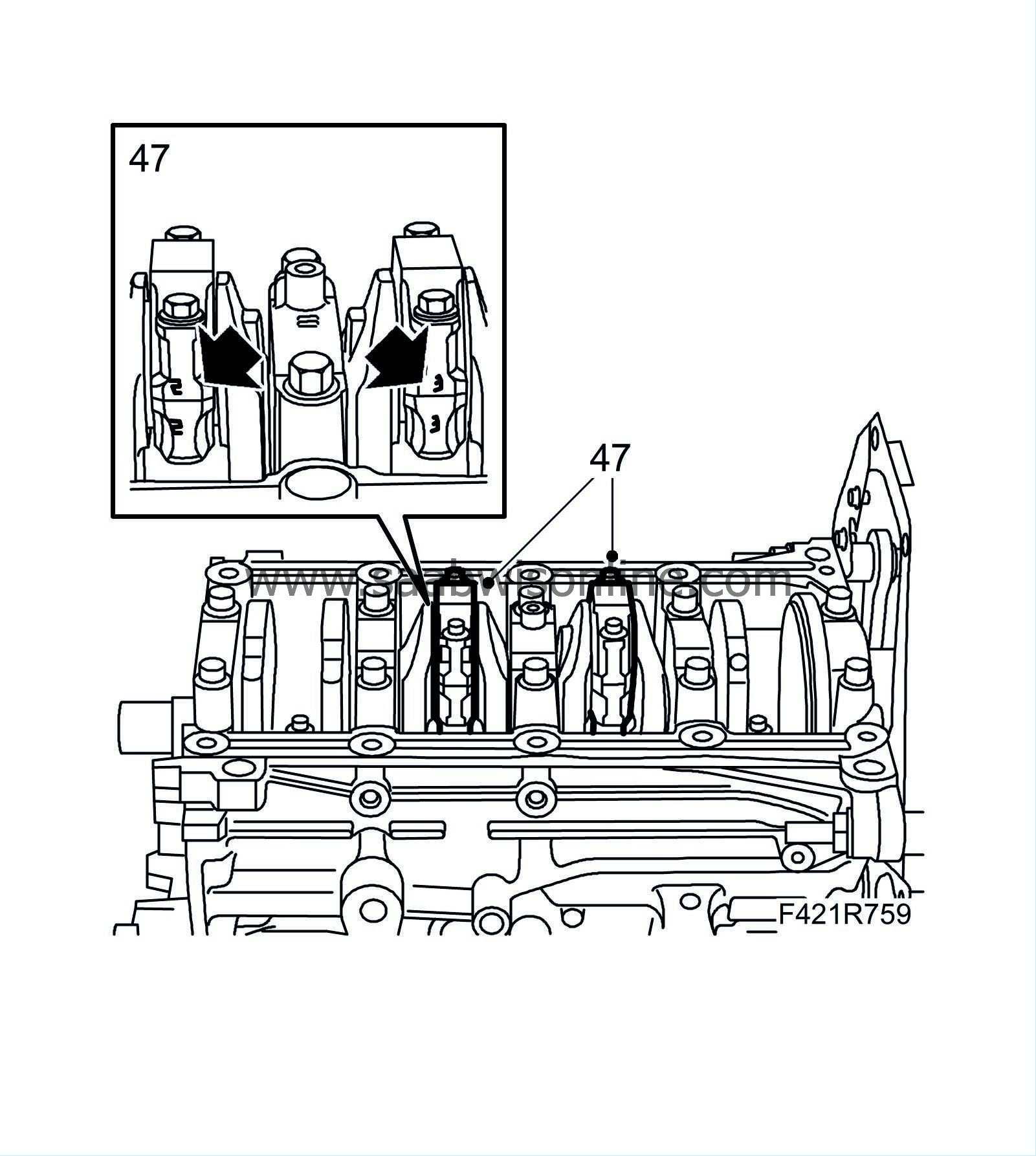
47.
|
Turn the crankshaft 1/2 turn and repeat points 40-46 on cylinders 2 and 3.
|
|
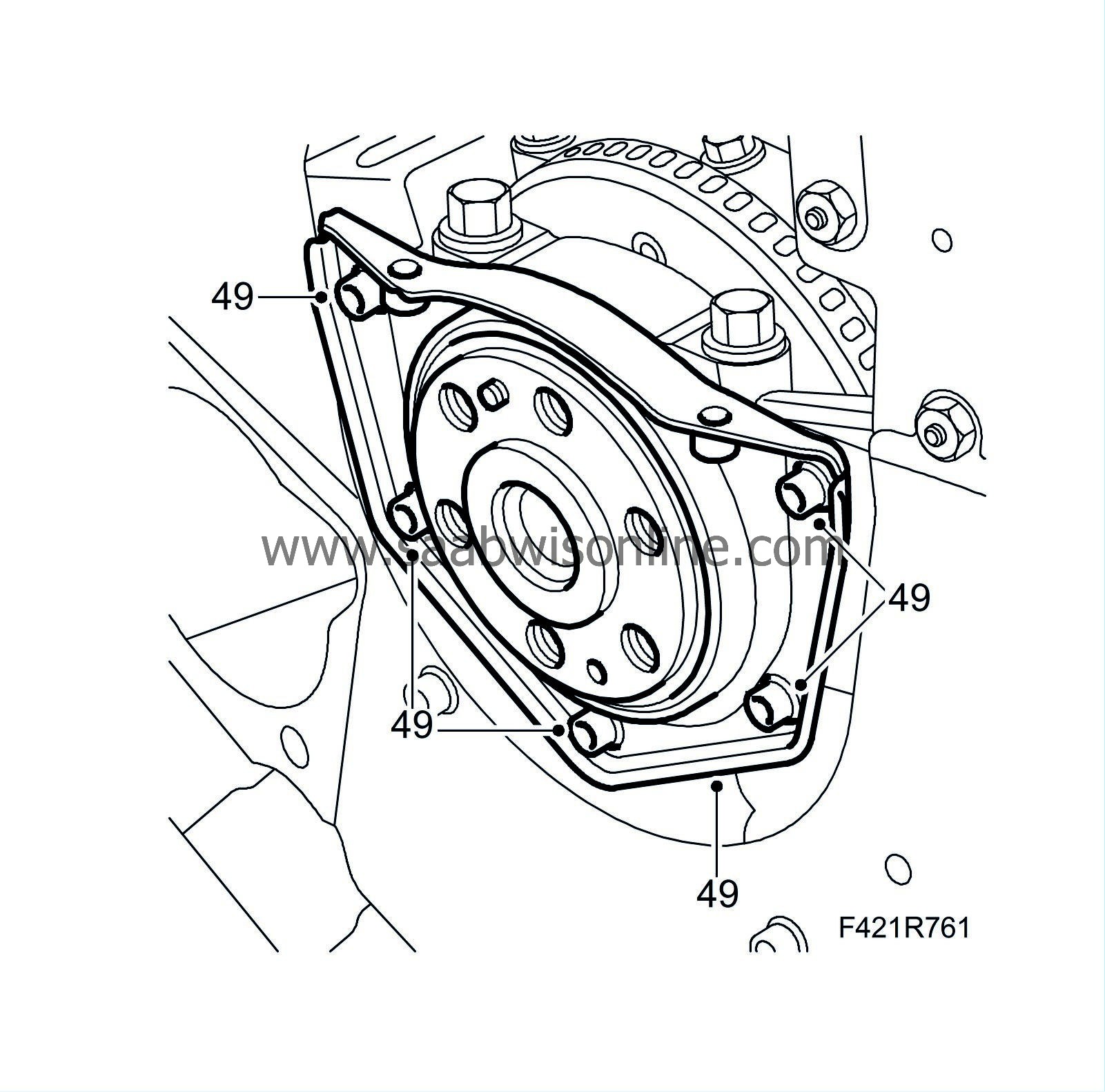
49.
|
Fit the bolts.
Tightening torque: 9 Nm (6 lbf ft)
|
|
50.
|
Clean the oil pump threads and sealing surfaces. Remove the seal.
|
|
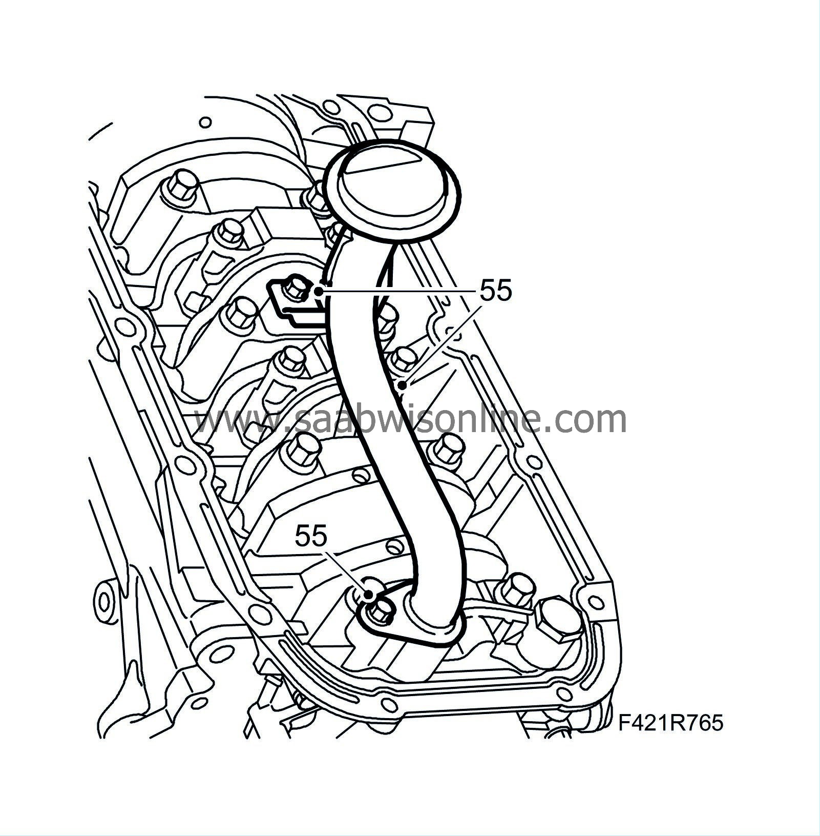
55.
|
Fit the oil intake pipe.
|
|
56.
|
Remove the oil sump baffle plate and clean the oil sump. Clean the sealing surfaces of the engine block and sump. Clean away and contaminants in the oil sump. Fit the oil sump baffle plate.
|
|
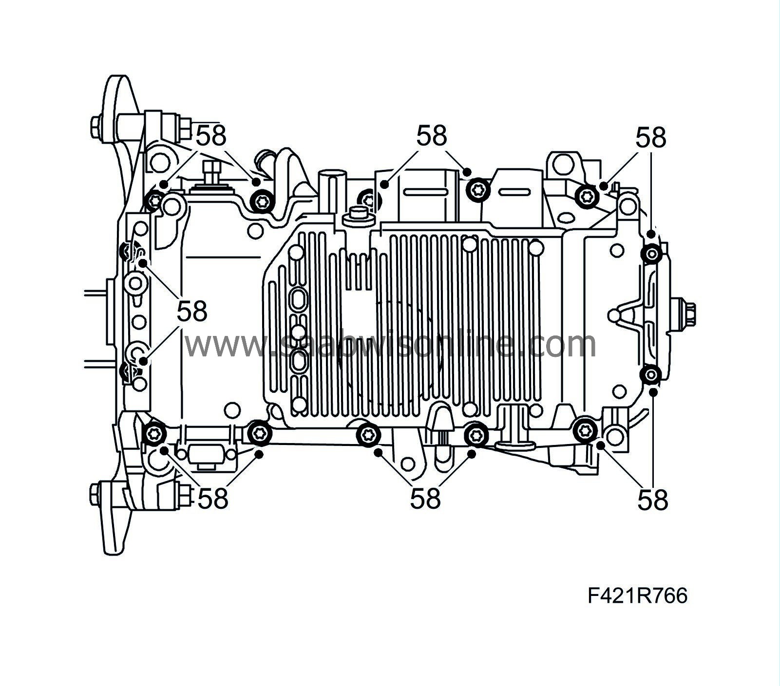
58.
|
Fit the oil sump carefully so that the sealing compound is not scraped away.
Tightening torque, M6 bolts: 9 Nm (7 lbf ft)
Tightening torque, M8 bolts: 25 Nm (18 lbf ft)
|
|
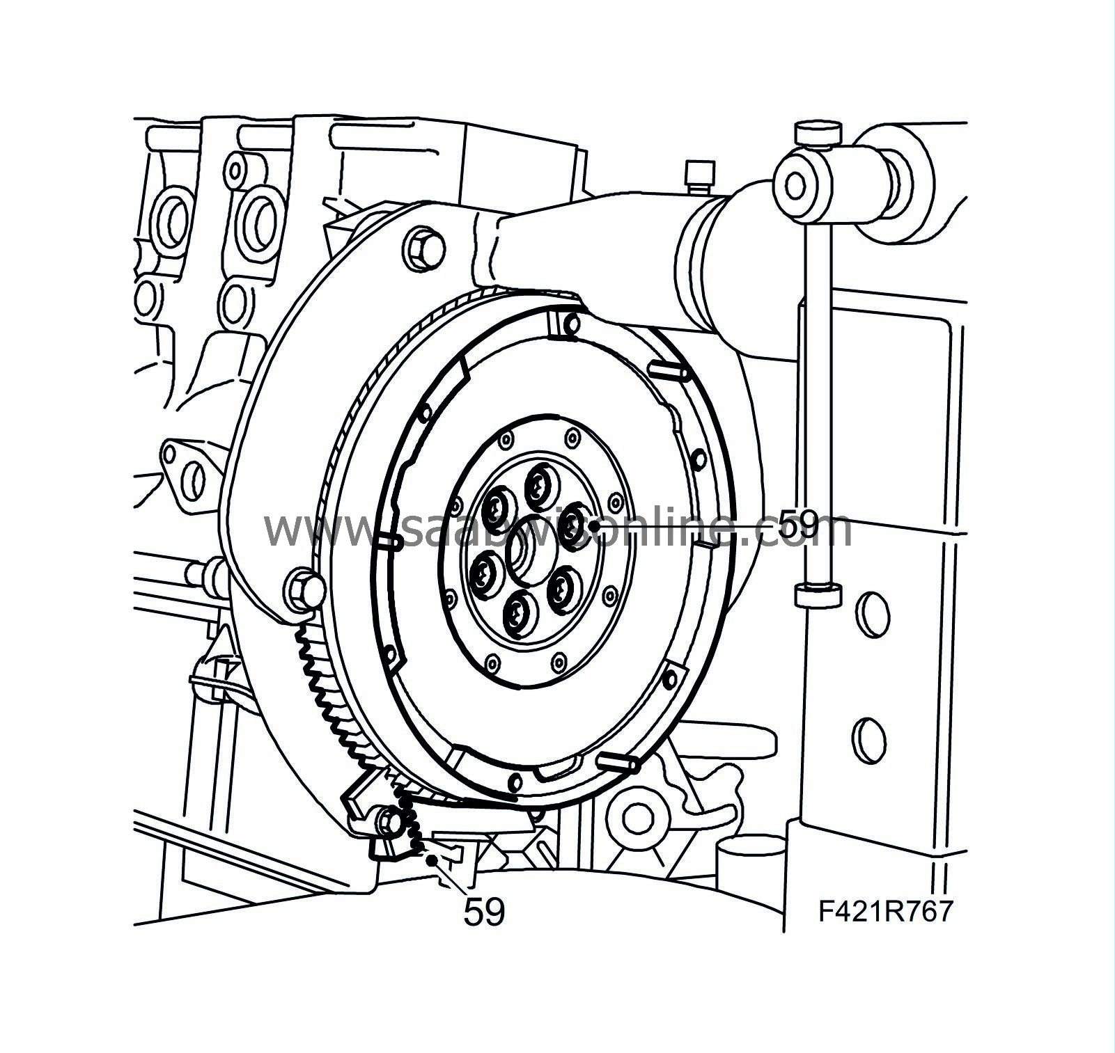
59.
|
Fit the flywheel or driver late using new bolts. Use
Thread locking adhesive, Loctite 270
on the bolts. Fit
83 92 987 Flywheel locking attachment
in the treaded hole in the oil sump so that the flywheel is locked in place. Tighten the bolts alternatingly.
Tightening torque: 160 Nm (118 lbf ft)
|
Important
|
|
The clutch plate and pressure plate have been matched with each other and must therefore be changed together.
|
|
|
|
|
60.
|
Man
: Position the driven plate and pressure plate on the flywheel. Insert the bolts but do not tighten completely. Apply
Thread locking adhesive, Loctite 242
to the threads. The convex side of the driven plate should face the gearbox.
|
|
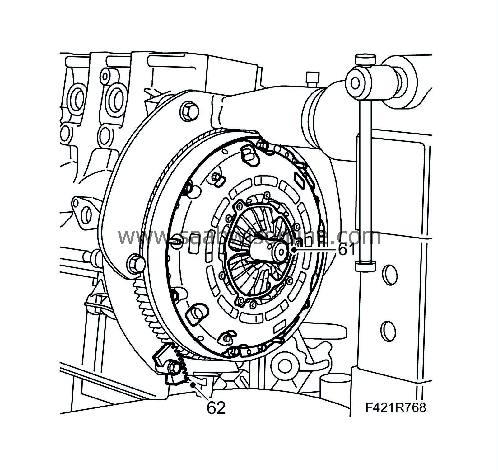
61.
|
Man
: Centre the driven plate using 83 96 277 Driven plate centring tool, 6-speed gearbox and tighten the bolts alternatingly.
Tightening torque: 30 Nm (22 lbf ft) (use thread locking adhesive)
|
|
62.
|
Remove the flywheel locking attachment and the centring tool.
|
|
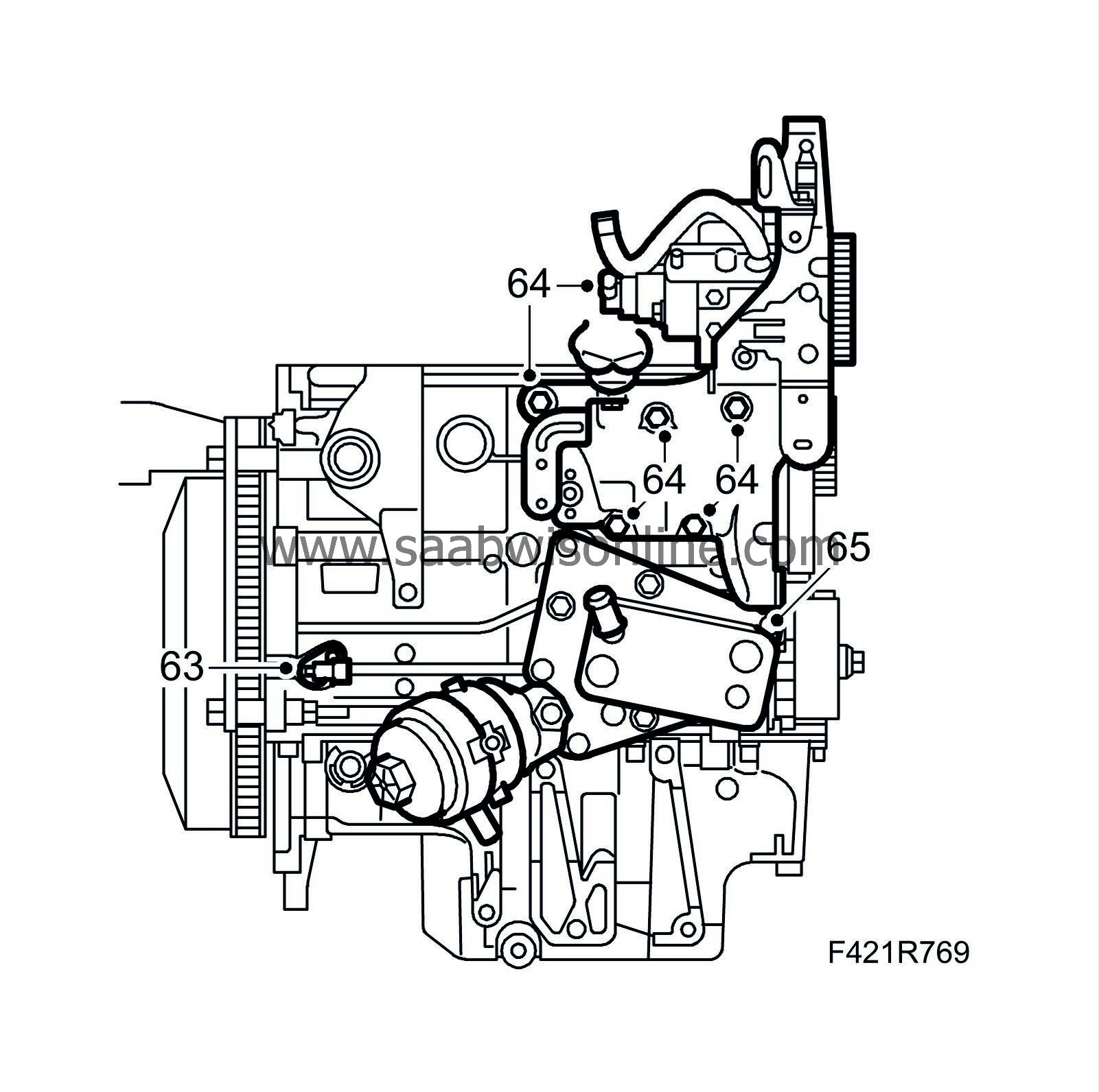
63.
|
Fit the crankshaft position sensor.
|
|
64.
|
Fit the fuel pump mounting.
Tightening torque: 25 Nm (18 lbf ft)
|
|
65.
|
Fit the oil cooler using new seals lubricated with vaseline.
Tightening torque: 50 Nm (37 lbf ft)
|
|
66.
|
Set cylinder 1's piston to TDC.
|
Important
|
|
Do not confuse the engine block guide sleeves with the camshaft guide sleeves.
|
|
|
|
|
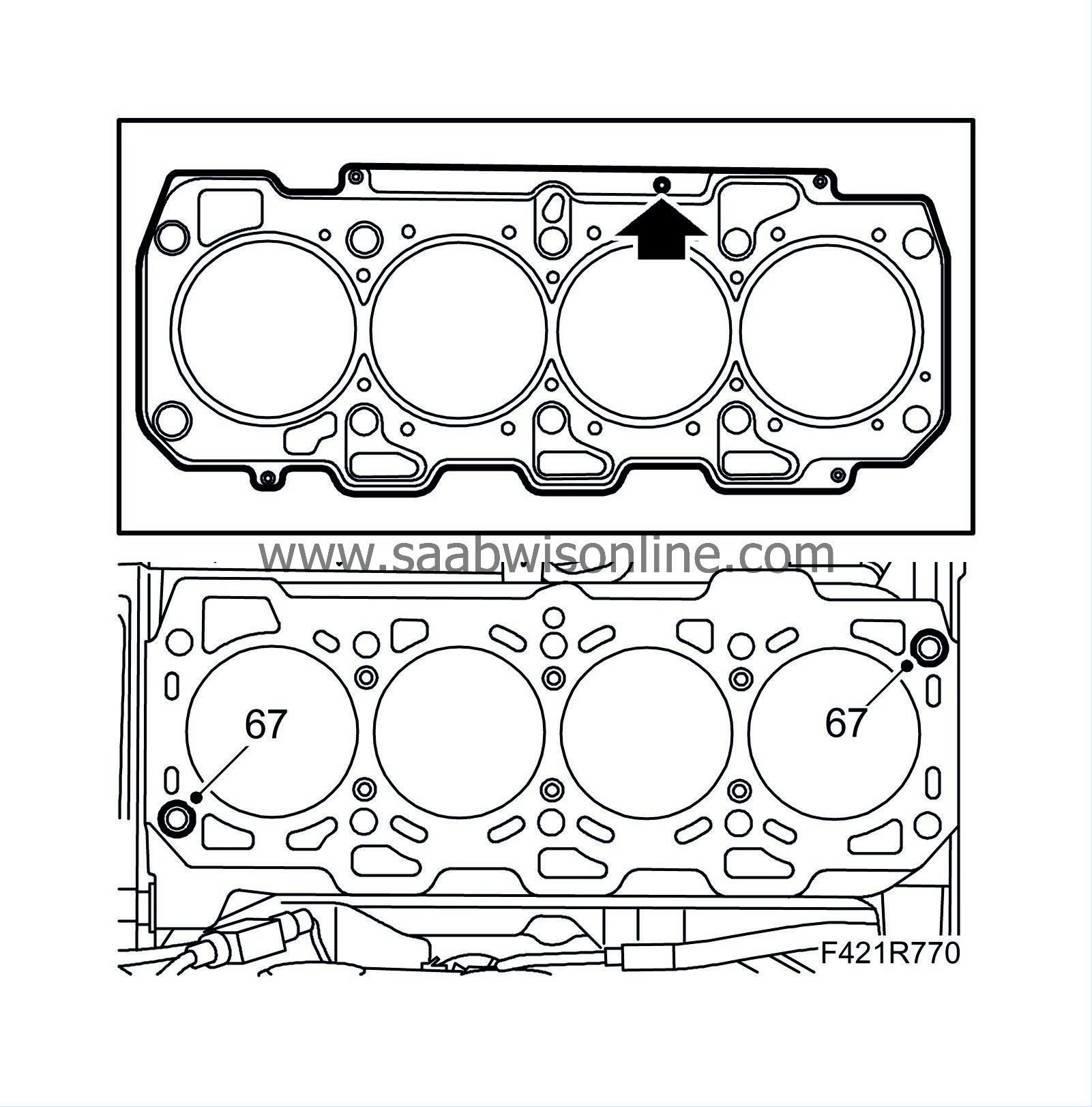
67.
|
Fit the guide sleeves on the engine block.
|
|
68.
|
Add a new gasket of the same thickness as the old one. If the connecting rods or pistons have been replaced measure piston height.
|
|
69.
|
Fit the cylinder head to the cylinder block.
|
|
70.
|
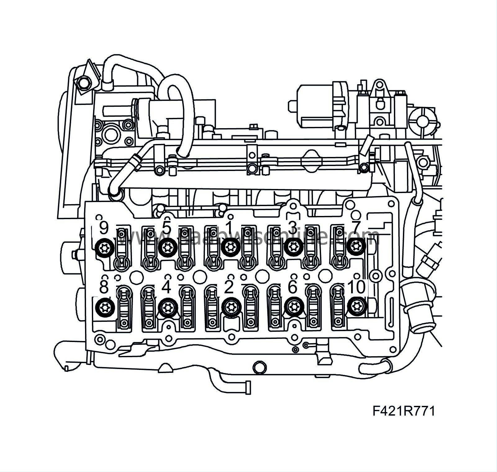
Tighten the cylinder head bolts in the order illustrated.
Tightening torque, step I: 65 Nm (48 lbf ft)
Step II: +90°
Step III: +90°
Step IV: +90°
|
|
71.
|
Clean away any gasket residue from the sealing surfaces of the cylinder head and camshaft housing.
|
|
72.
|
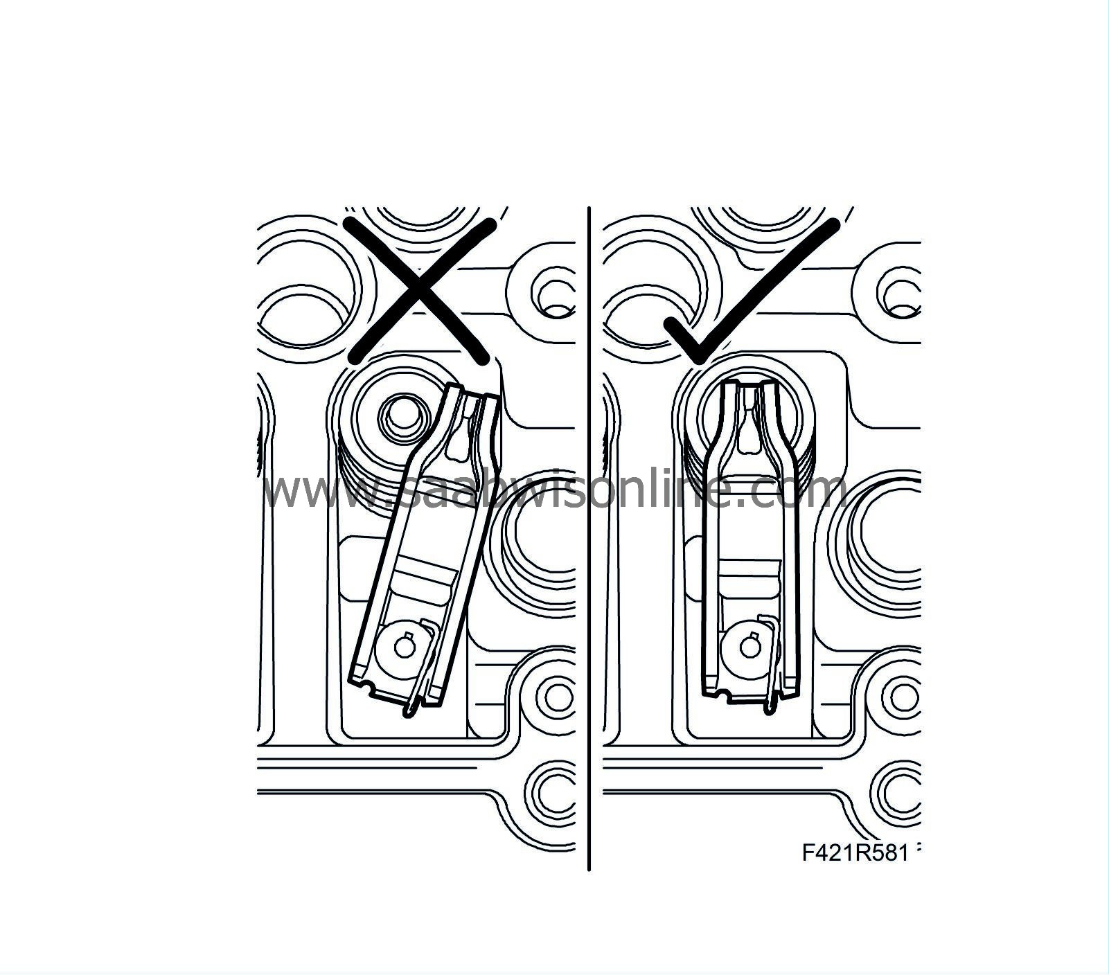
Fit the guide sleeves and position a new gasket on the cylinder head.
|
Note
|
|
Check that all rocker arms are properly positioned on the valve stem.
|
|
|
73.
|
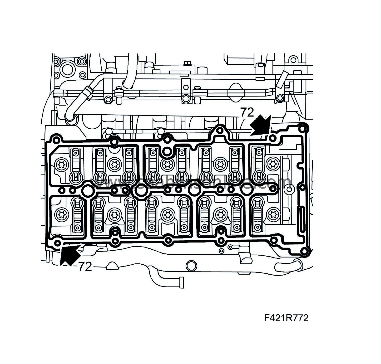
Fit the camshaft housing, tightening the bolts alternatingly. Check that the guide sleeves are properly positioned in the camshaft housing.
Tightening torque: 25 Nm (18 lbf ft)
|
|
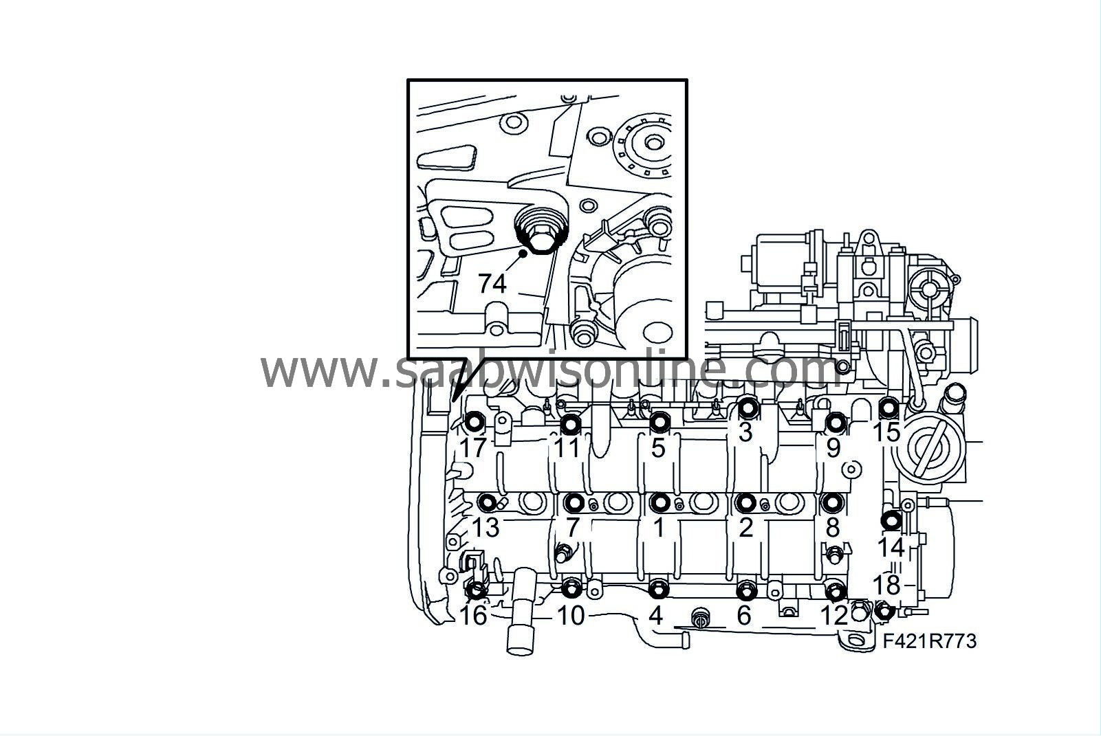
74.
|
Screw in the spacer sleeve to the cylinder head and fit the bolt.
|
|
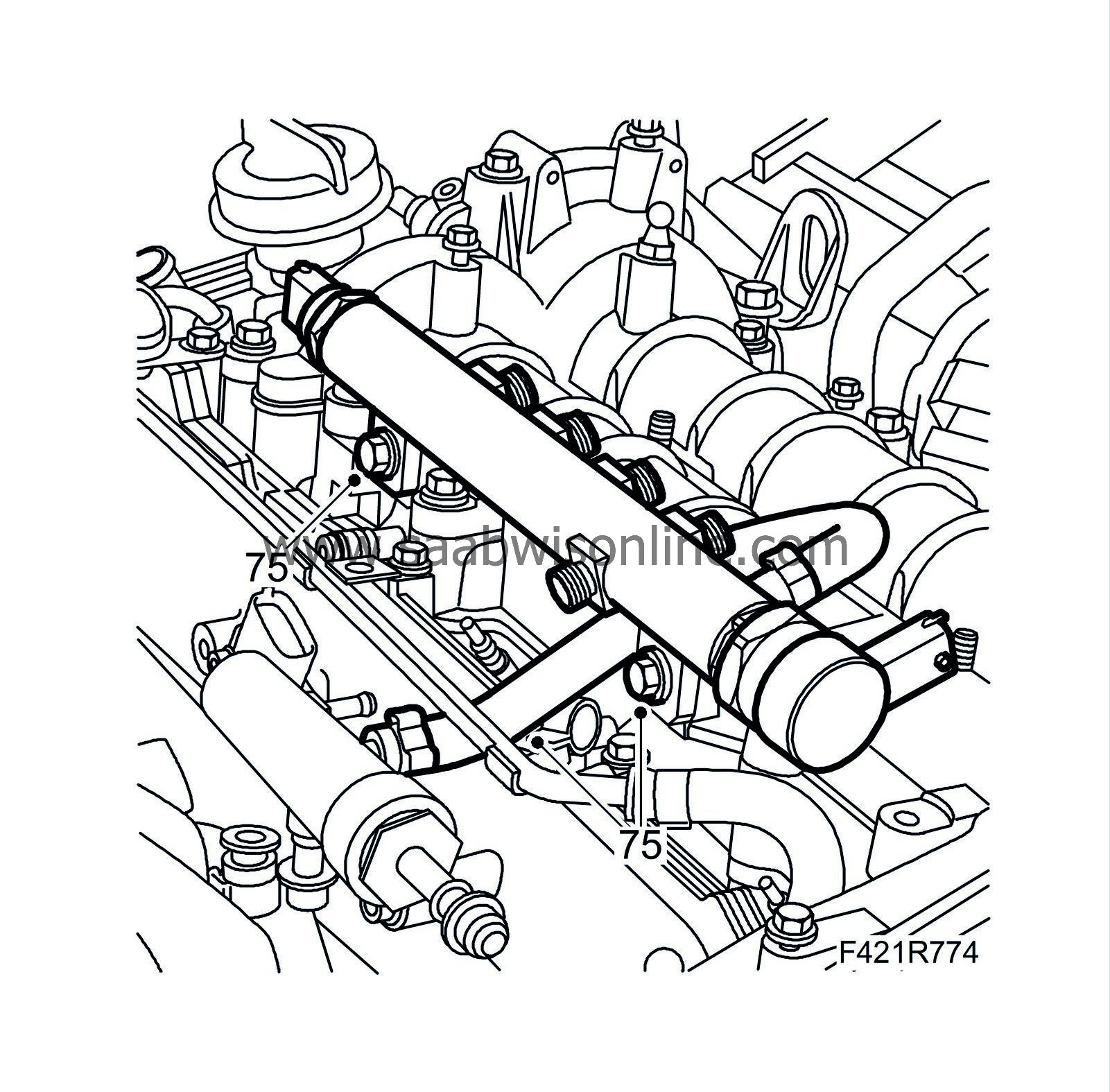
75.
|
Fit the fuel rail and hose.
|
|
77.
|
Fit the injectors following the cylinder marking. Use new seals and fit in the order 4-3-2-1.
Tightening torque: 25 Nm (18 lbf ft)
|
|
78.
|
Check that the fuel pipe sealing surfaces are clean and undamaged. Fit the pipes without tension and fit the nuts by hand. Tighten the nuts. Counterhold on the injectors using an open-ended wrench.
Tightening torque: 25 Nm (18 lbf ft)
|
|
79.
|
Attach the return fuel hoses.
|
|
80.
|
Attach the fuel delivery pipe between the pump and fuel rail.
Tightening torque: 25 Nm (18 lbf ft)
|
|
81.
|
Attach the return fuel hose to the return fuel tank.
|
|
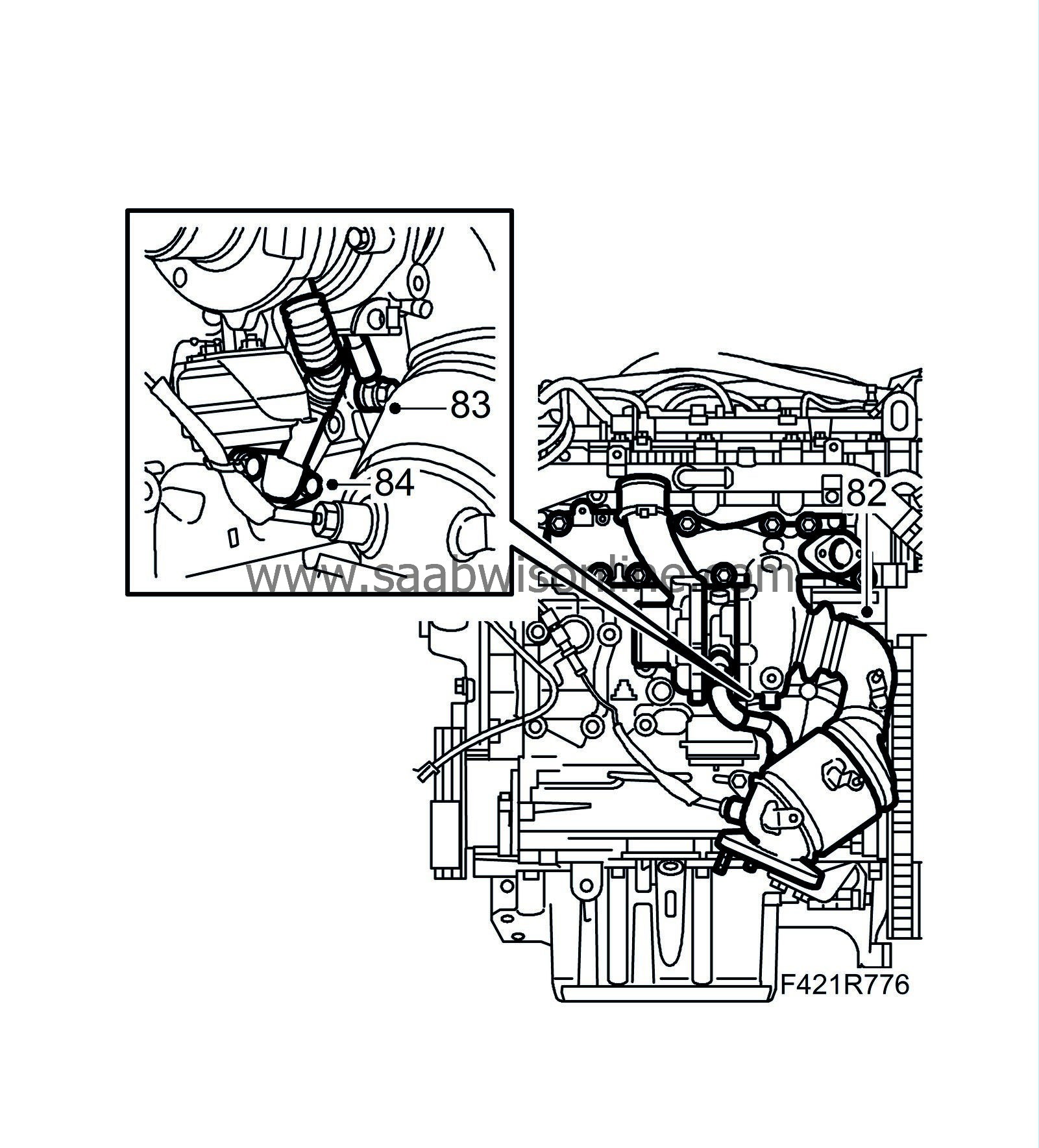
82.
|
Fit the turbocharger with catalytic converter using a new gasket.
Tightening torque: 20 Nm (15 lbf ft)
|
|
83.
|
Attach the oil delivery pipe to the engine block using new gaskets.
Tightening torque: 15 Nm (11 lbf ft)
|
|
84.
|
Attach the turbocharger oil return pipe using a new gasket.
Tightening torque: 25 Nm (18 lbf ft)
|
|
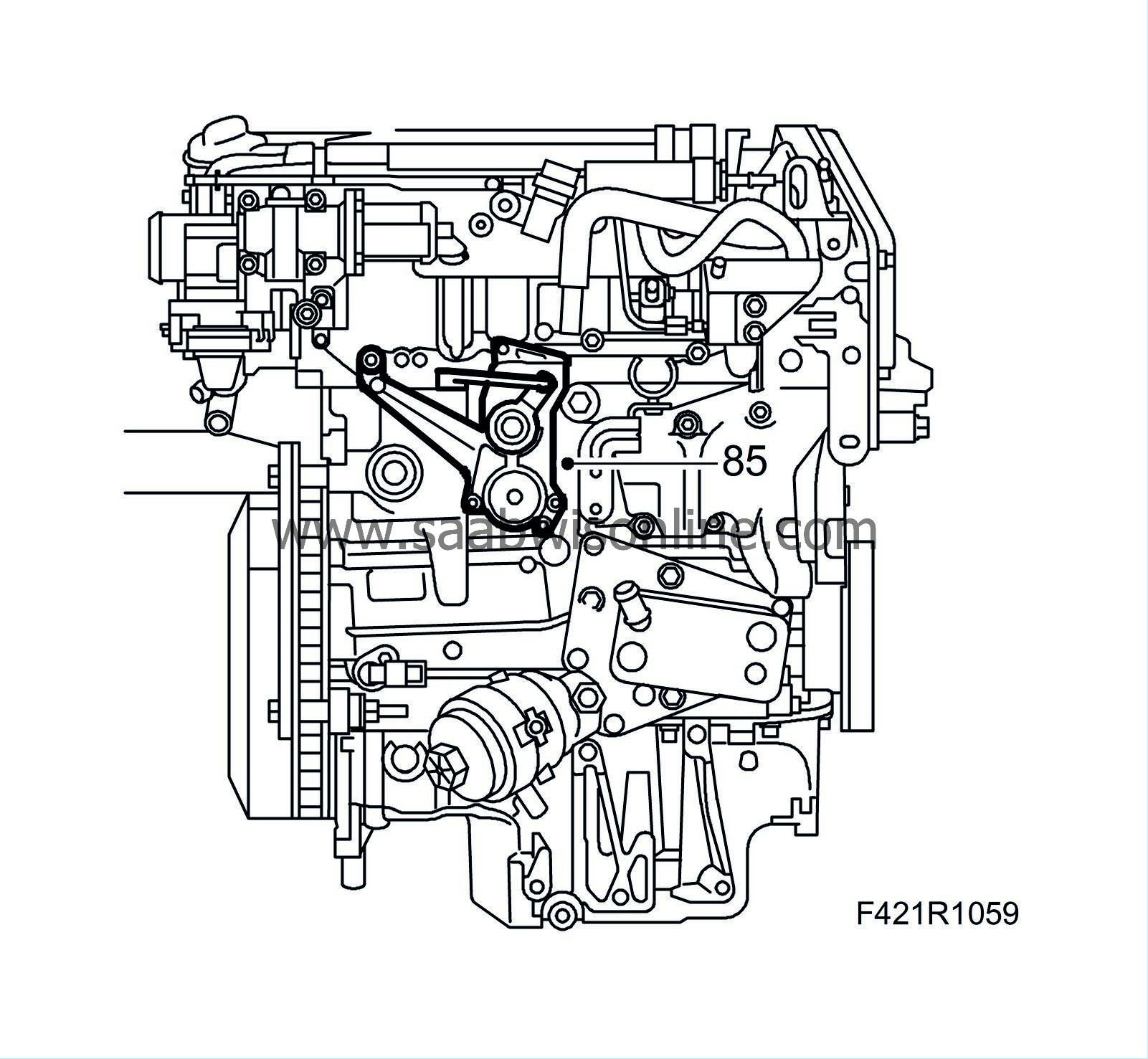
85.
|
Fit the combustion circulation actuator (403). Press the control arm onto the ball coupling using suitable pliers.
|
|
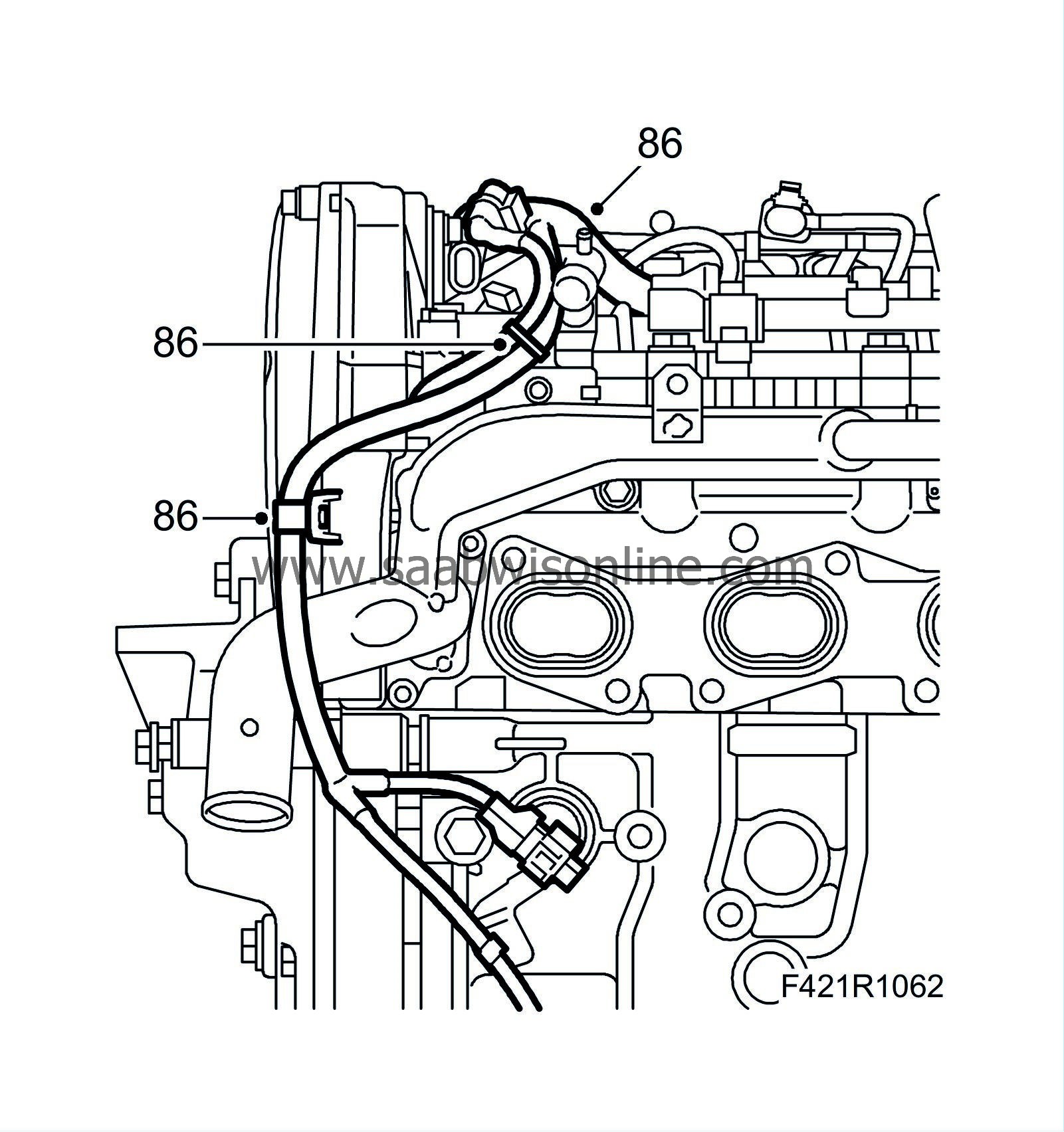
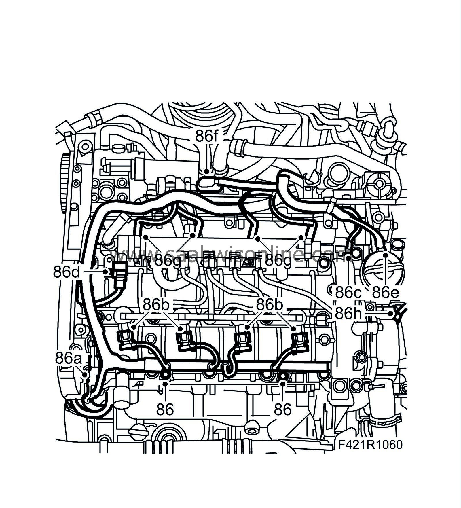
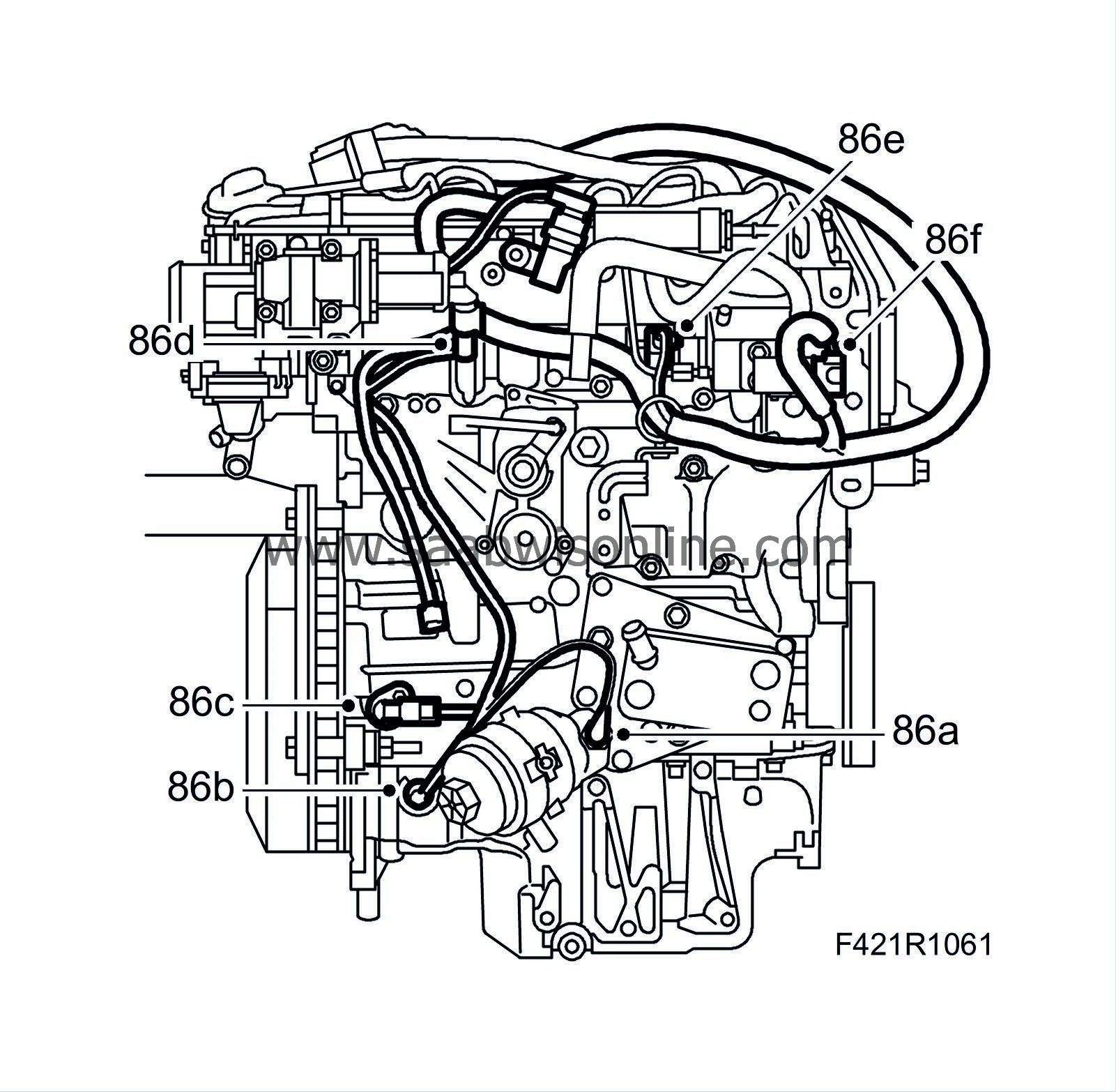
86.
|
Position the wiring harness. Plug in the following connectors:
|
|
|
86.a.
|
Camshaft position sensor (555)
|
|
|
86.c.
|
Fuel pressure sensor (653).
|
|
|
86.d.
|
Fuel pressure solenoid valve (652a).
|
|
|
86.e.
|
Electronic throttle actuator (604)
|
|
|
86.f.
|
Sensor, intake air (688)
|
|
|
86.g.
|
Glow plug connector
|
|
|
86.h.
|
Coolant temperature sensor (202)
|
|
|
86.i.
|
Engine oil pressure switch (44)
|
|
|
86.j.
|
Level switch, engine oil (243)
|
|
|
86.k.
|
Crankshaft position sensor (345)
|
|
|
86.l.
|
Combustion circulation actuator (403)
|
|
|
86.m.
|
EGR solenoid valve (606)
|
|
|
86.n.
|
Fuel quantity solenoid valve, high pressure pump (652b)
|
|
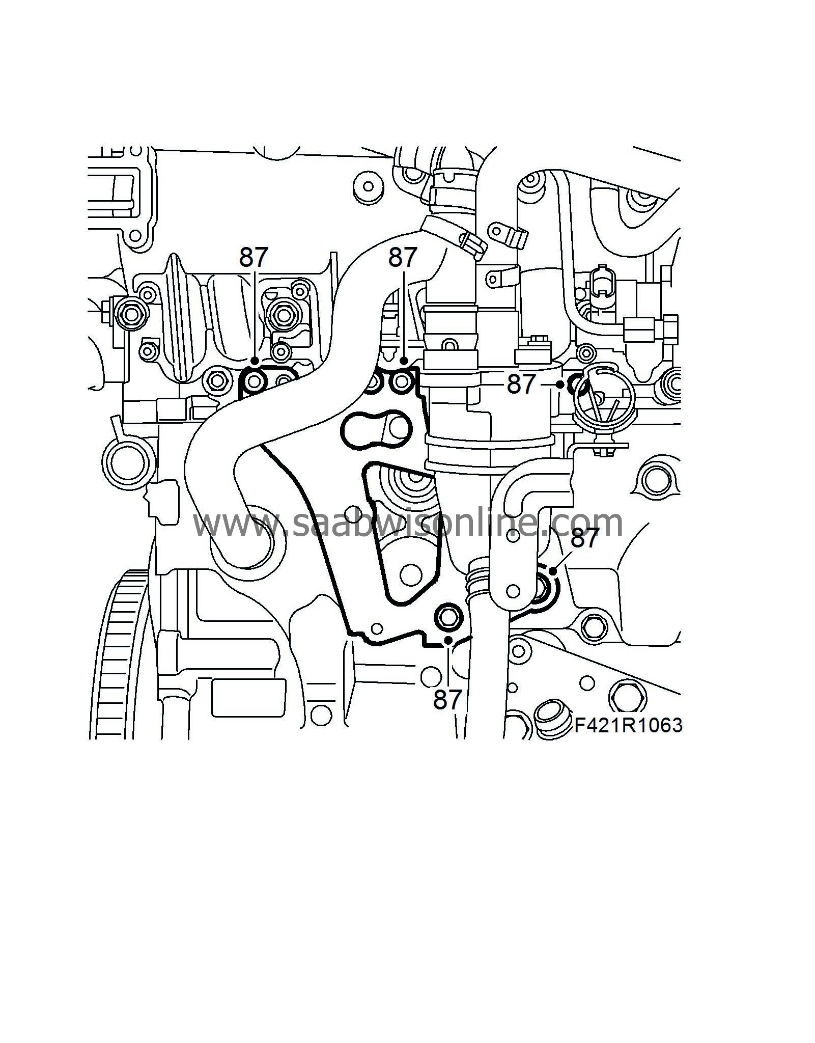
87.
|
Fit the oil trap bracket.
|
|
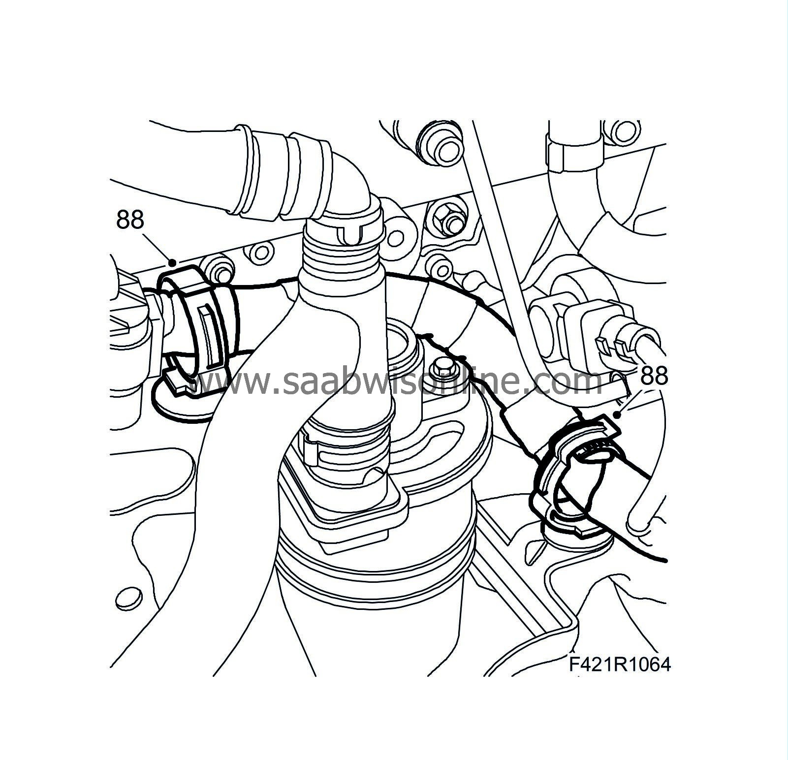
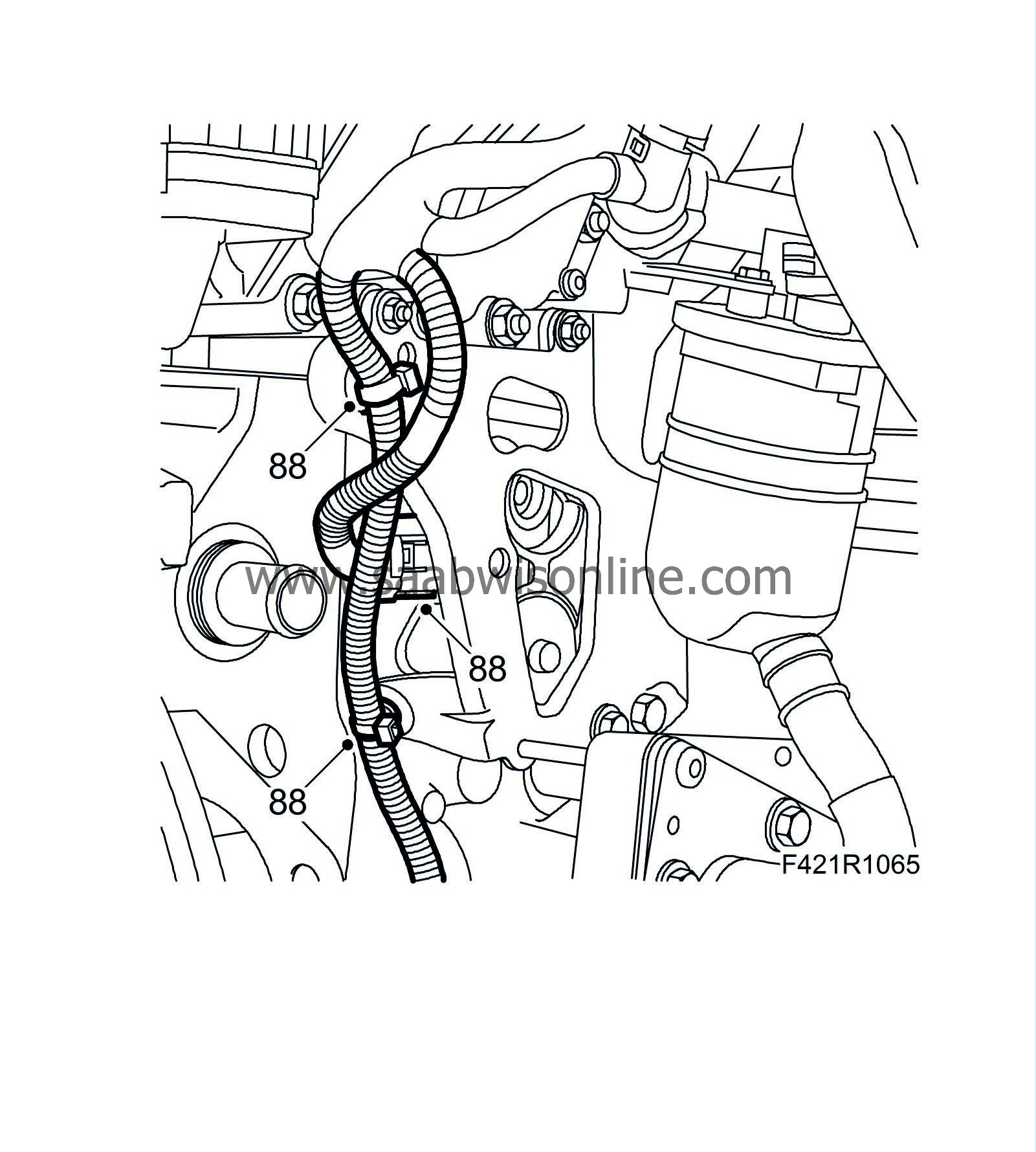
88.
|
Fit the wiring harness clips.
|
|
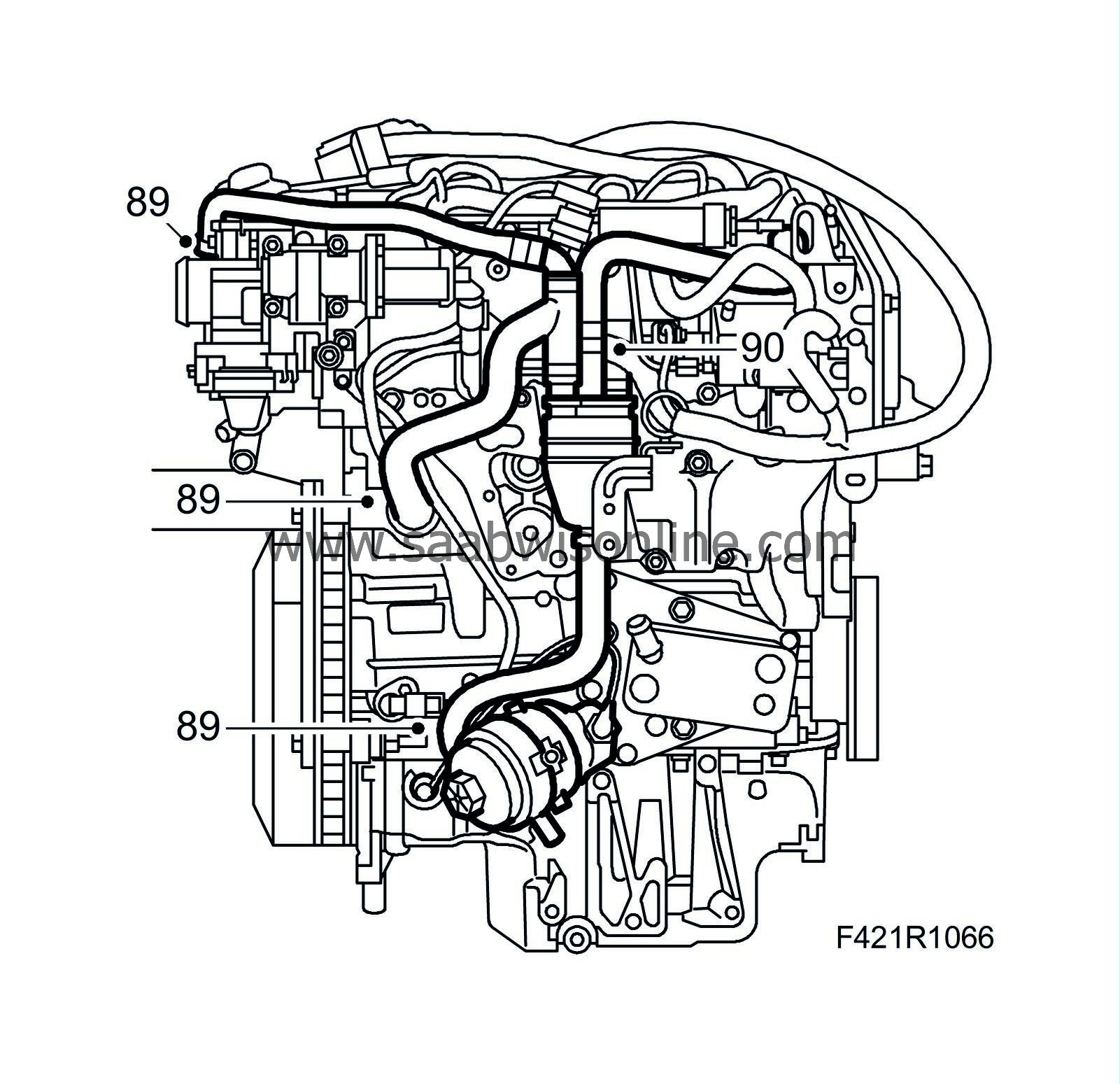
89.
|
Attach the crankcase ventilation hoses to the engine block, oil sump and oil filler port.
|
|
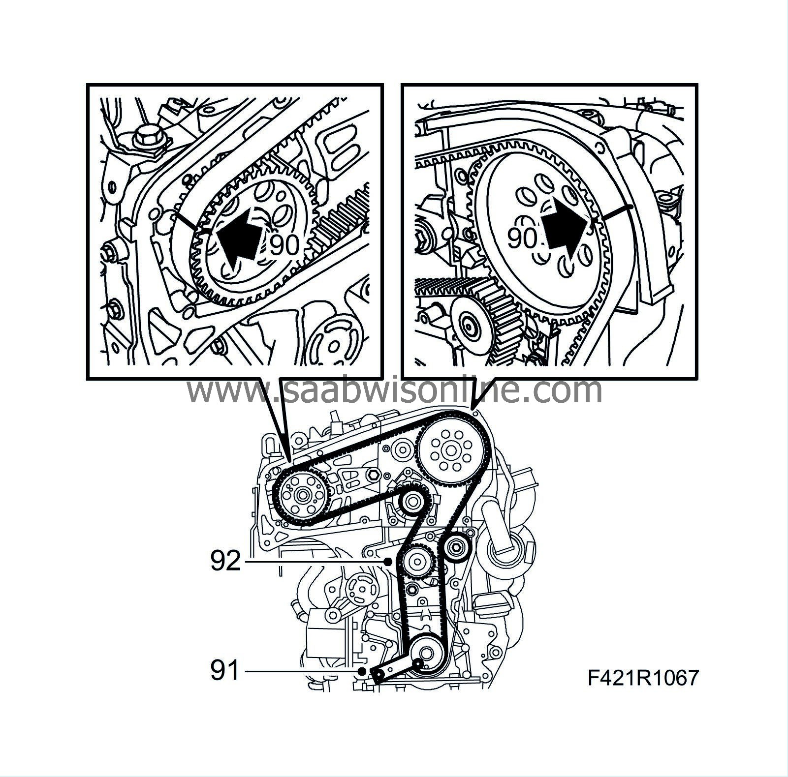
90.
|
Fit the timing belt so that the markings on the belt align with the markings on the crankshaft, exhaust camshaft and fuel pump sprockets.
|
|
92.
|
Fit the belt tensioner but do not tighten the bolt.
|
|
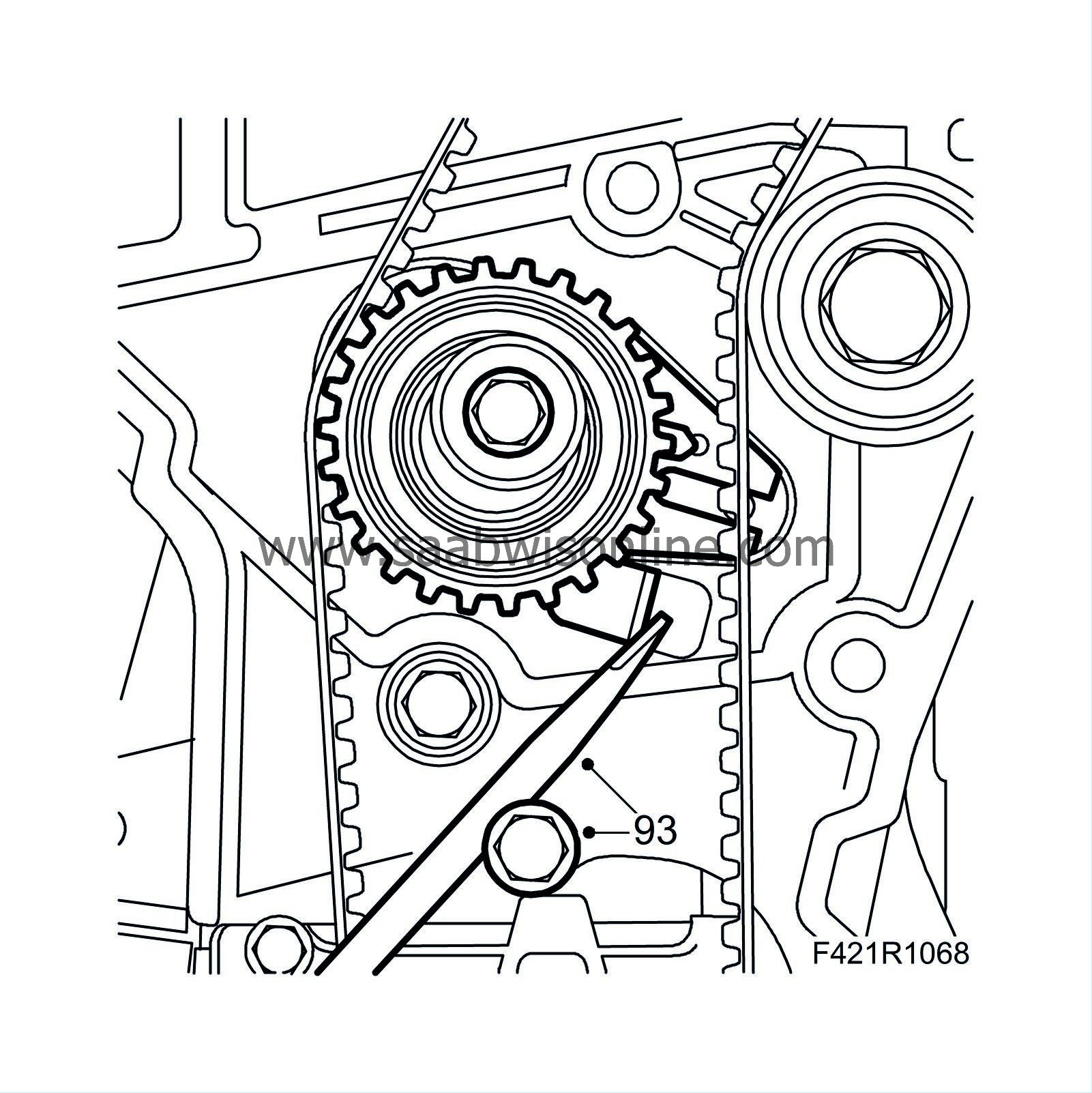
93.
|
Adjust by pushing the adjustment lever in the direction of the arrow until the belt tensioner arrow aligns with the marking. Tighten the belt tensioner using a large screwdriver and an M8 bolt as counterhold.
Tightening torque: 25 Nm (18 lbf ft)
|
|
94.
|
Remove the adjustment tools and turn the crankshaft 2 rotations.
|
|
96.
|
Remove the tools. Fit the plug in the camshaft housing and the bolts of the oil pump.
|
|
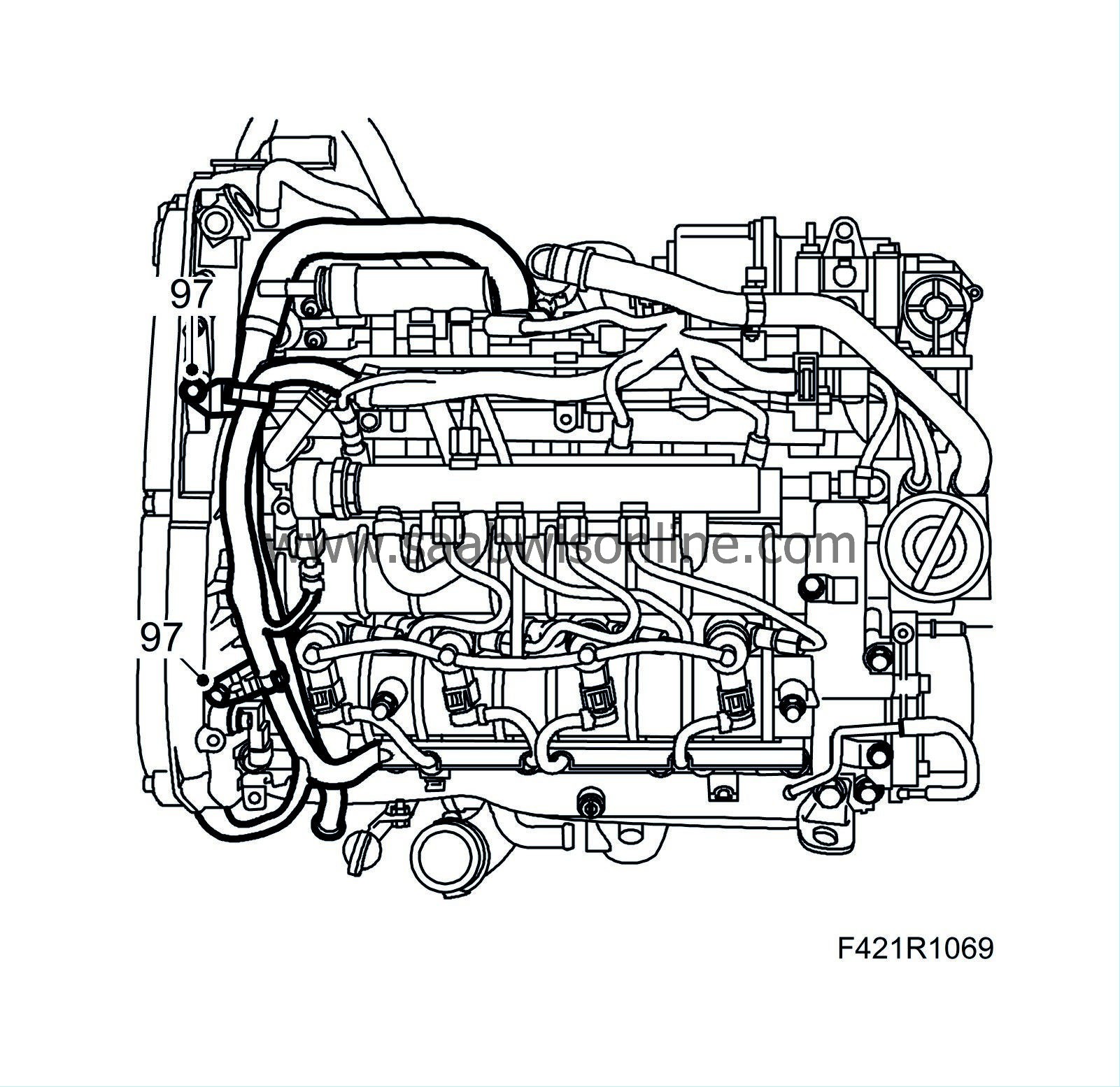
97.
|
Attach the crankcase ventilation pipe and hose on the camshaft housing.
|
|
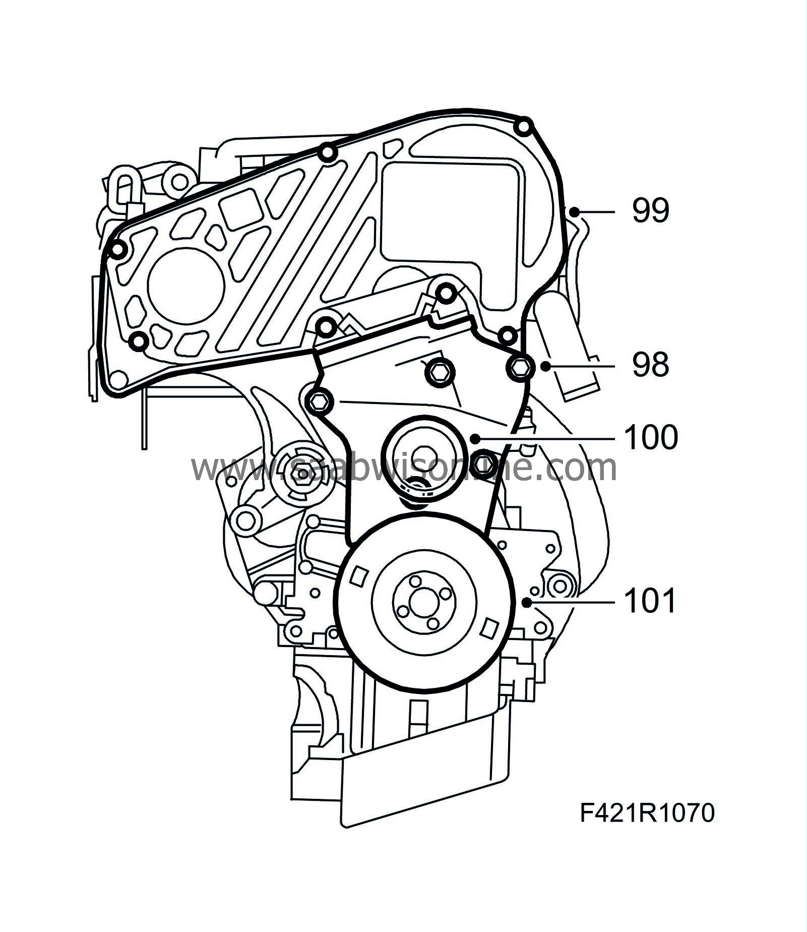
98.
|
Fit the lower timing cover.
|
|
99.
|
Fit the upper timing cover.
|
|
100.
|
Fit the idler pulley centre bolt on the lower timing cover.
Tightening torque: 25 Nm (18 lbf ft)
|
|
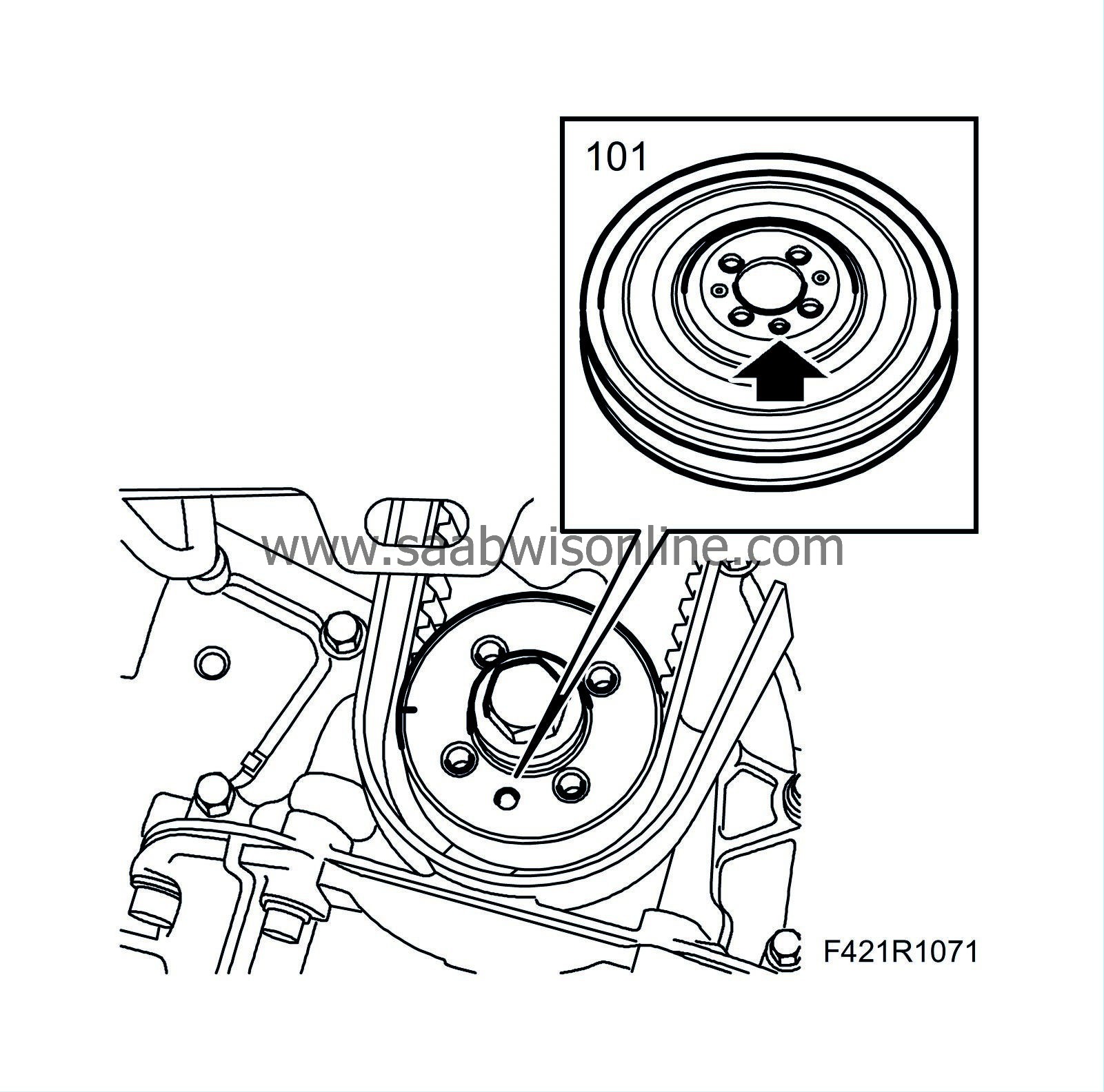
101.
|
Fit the crankshaft pulley.
|
Note
|
|
Make sure that the guide pin sits properly in its recess.
|
Tightening torque: 25 Nm (18 lbf ft)
|
|
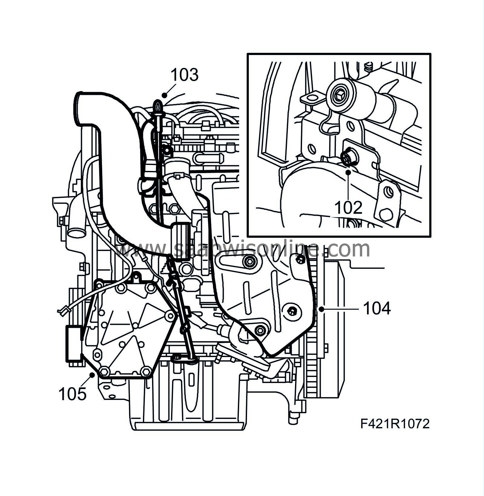
102.
|
Fit the mounting of the turbocharger intake manifold.
|
|
103.
|
Fit the dipstick guide tube.
|
|
104.
|
Fit the heat shield.
|
|
105.
|
Fit the A/C bracket.
|
|
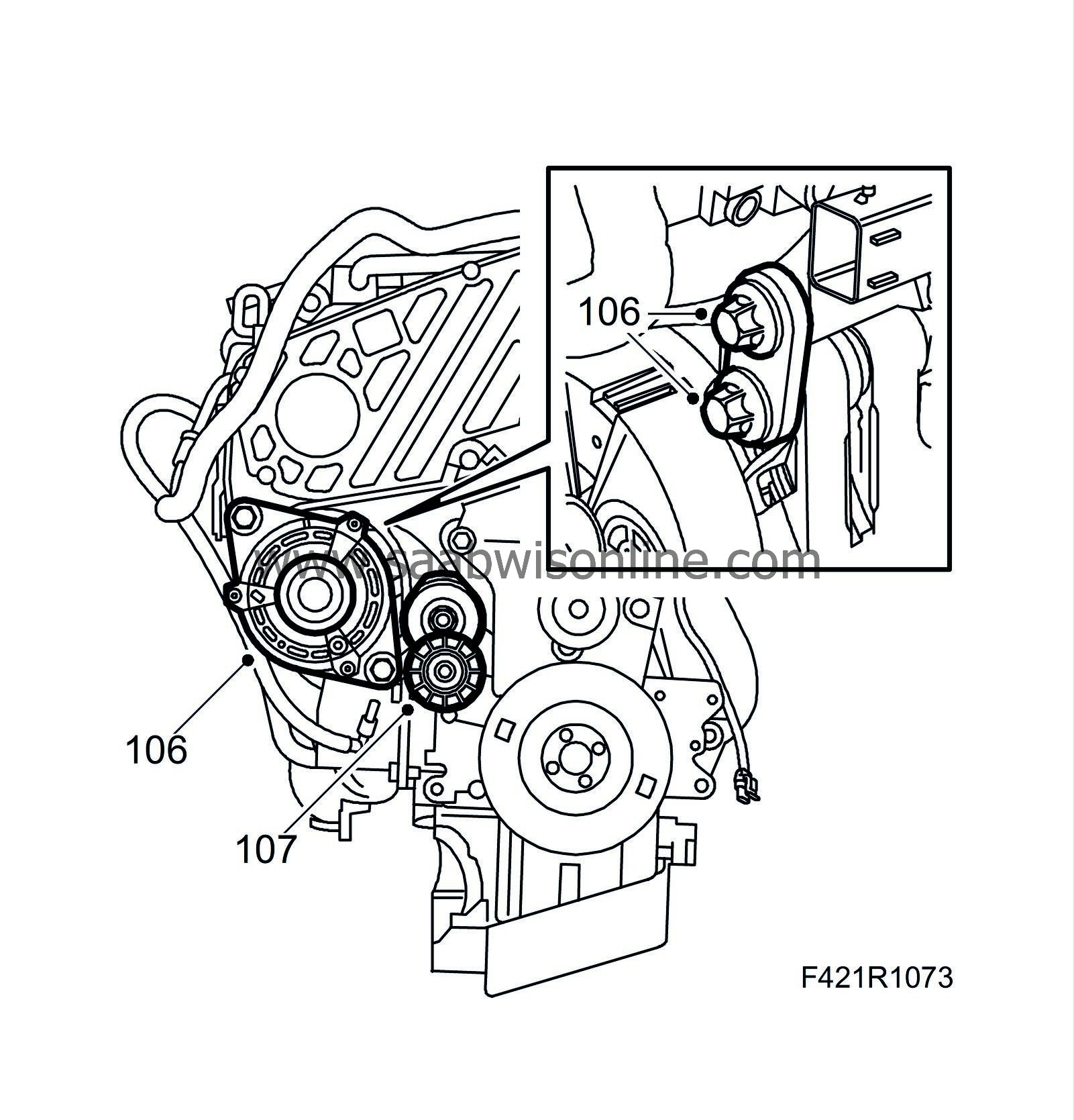
106.
|
Fit the generator.
|
|
107.
|
Fit the belt tensioner.
|
|
109.
|
Check that the two guide sleeves sit on the engine. Grease the guide sleeves.
|
|
111.
|
Man
: Fit the gearbox to the engine.
Tightening torque, M10: 40 Nm (30 lbf ft)
Tightening torque, M12: 60 Nm (44 lbf ft)
|
|
112.
|
Aut:
Turn the torque converter so that the bolt holes align with the holes on the driver plate and turn the engine so that the oval hole in the driver is centred at the starter motor opening. Grease the torque converter guide pin.
|
|
113.
|
Aut
: Fit the gearbox to the engine. Remove
87 92 574 Holder
just before the gearbox is in place. Tighten the bolts between the engine and gearbox.
Tightening torque: M10 40 Nm (30 lbf ft)
Tightening torque: M12 60 Nm (44 lbf ft)
|
|
114.
|
Aut
: Press the torque converter toward the driver plate. Fit the plug.
|
|
115.
|
Aut
: Apply
Thread locking adhesive, Loctite 270
to the bolts that hold the torque converter to the driver plate.
|
Note
|
|
Use the original bolts with accompanying washers. Bolts that are too long can cause damage to the torque converter.
|
|
|
116.
|
Aut
: Rotate the engine clockwise at the pulley and tighten the bolts one at a time starting at the oval hole in the driver plate.
Tightening torque: 30 Nm (22 lbf ft).
|
|
117.
|
Aut
: Replace oil duct hose seals (does not apply to new gearbox). Use
83 90 270 Sliding hammer
,
87 92 319 Adapter, 3/8" - M10
and 87 92 756 Puller, oil pipe seal, automatic transmission.
|
Important
|
|
Ensure that the surfaces in the gearbox gasket opening are not damaged.
|
|
|
|
|
118.
|
Aut
: Fit new oil cooling hose seals greased with vaseline. Use 87 92 814 Fitting tool, oil pipe seal, automatic transmission.
|
|
119.
|
Aut
: Grease the pipes with acid-free vaseline and fit the oil cooling hoses. The pipes press holes in the seals during fitting.
|
|
120.
|
Fit the front catalytic converter mounting.
|
|
121.
|
Fit the starter motor with the bracket for the coolant pipe and wiring harness.
Tightening torque 24 Nm (18 lbf ft)
|
|
122.
|
Fit a new oil filter.
|
|
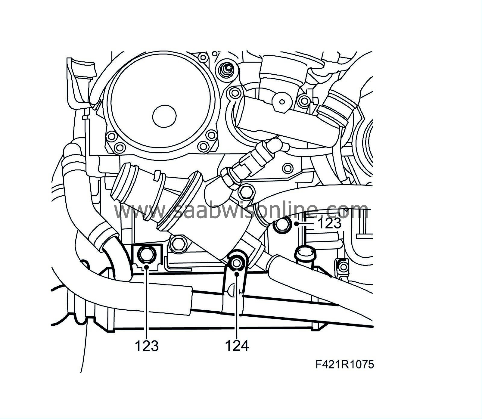
123.
|
Fit the new EGR cooler using new seals.
Tightening torque to cylinder head: 25 Nm (18 lbf ft)
Tightening torque to EGR valve: 20 Nm (15 lbf ft)
Tightening torque to exhaust manifold: 20 Nm (15 lbf ft)
|
|
124.
|
Position and attach the coolant pipes to the oil cooler and engine.
|
|
125.
|
Fit the wiring harness and connect it to the generator and starter motor.
|
|
126.
|
Raise the power unit on the subframe.
|
|
127.
|
Tighten the torque arms to the subframe.
Tightening torque, front arm: 60 Nm +90° (44 lbf ft +90°)
Tightening torque, rear arm: 80 Nm (59 lbf ft)
|
|
128.
|
Connect the wiring harness to the EHPS unit.
|
|
129.
|
Remove the lifting eye.
|


