Changing balancer shaft chain/timing chain in car
|
|
Changing balancer shaft chain/timing chain in car
|
|
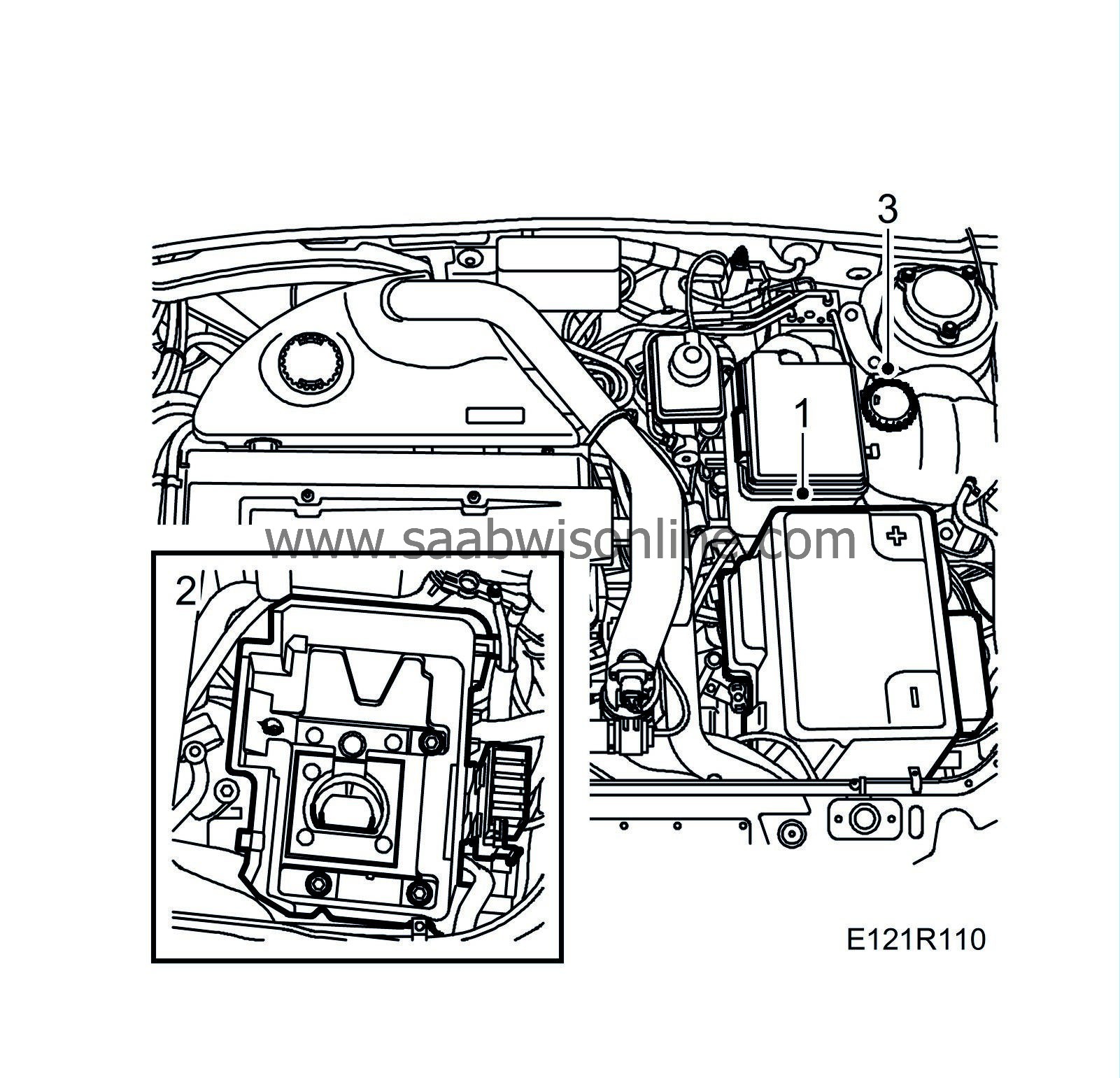
1.
|
Remove the battery cover and the battery.
|
|
2.
|
Remove the battery tray.
|
|
3.
|
Open the expansion tank cap.
 Warning
|
|
The cooling system is under pressure. Hot coolant and steam can escape.
|
|
- Open the cap slowly to release the pressure.
|
|
- Carelessness can cause eye and burn injuries
|
|
|
|
|
|
|
|
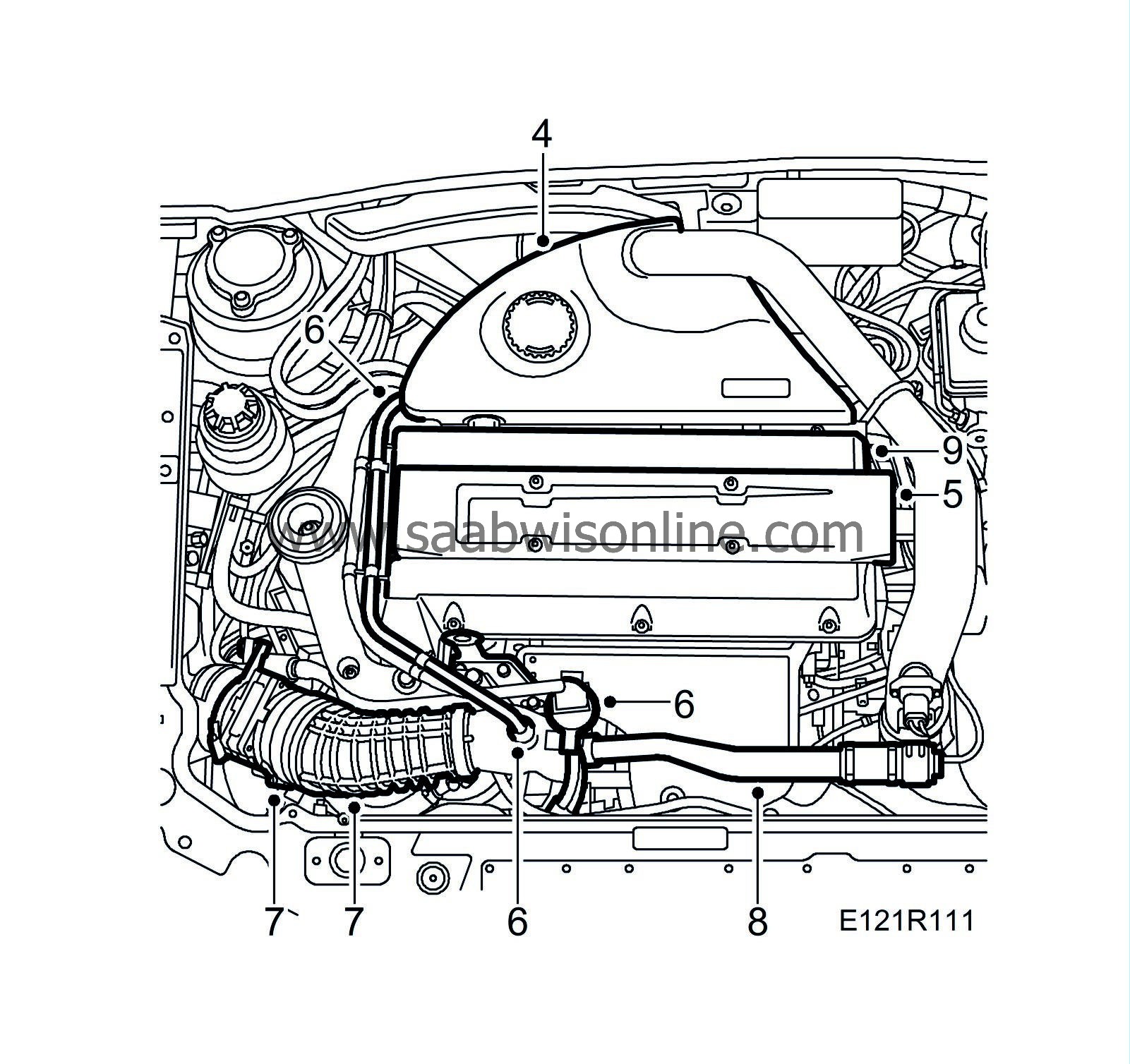
4.
|
Remove the upper engine cover.
|
|
5.
|
Remove the ignition discharge module and the spark plugs.
|
|
6.
|
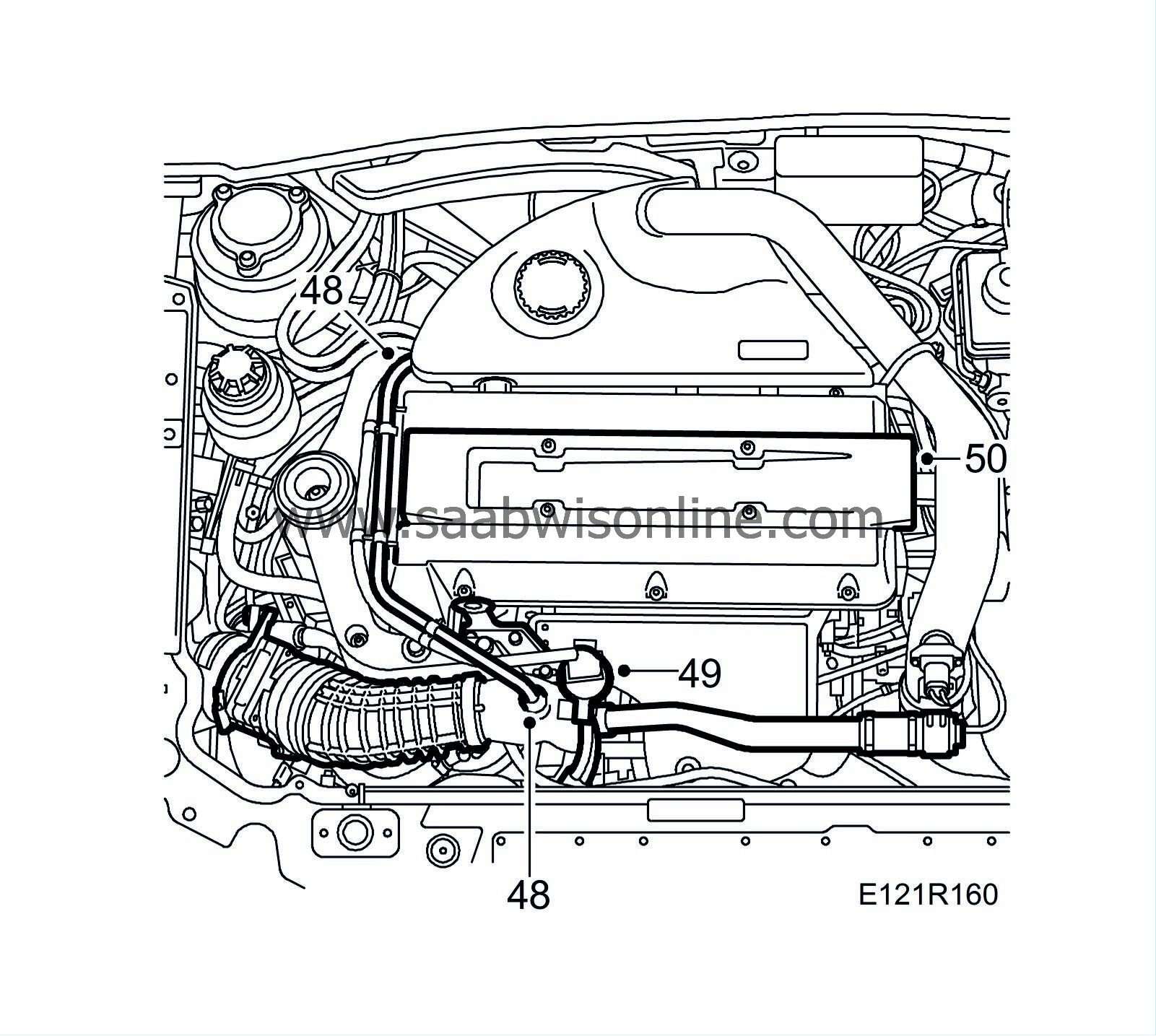
Remove the crankcase ventilation pipe. Unplug the solenoid valve connector.
|
|
7.
|
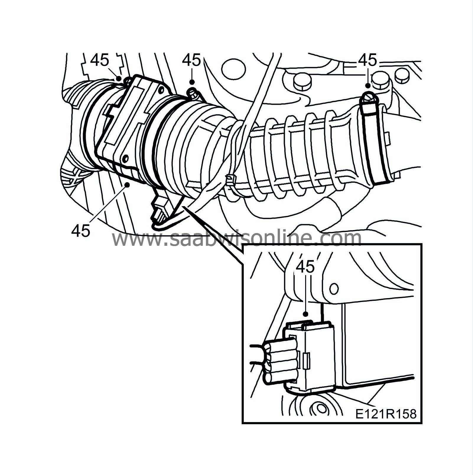
Remove the mass air flow sensor and the intake hose
|
|
8.
|
Remove the by-pass valve with pipe.
|
|
9.
|
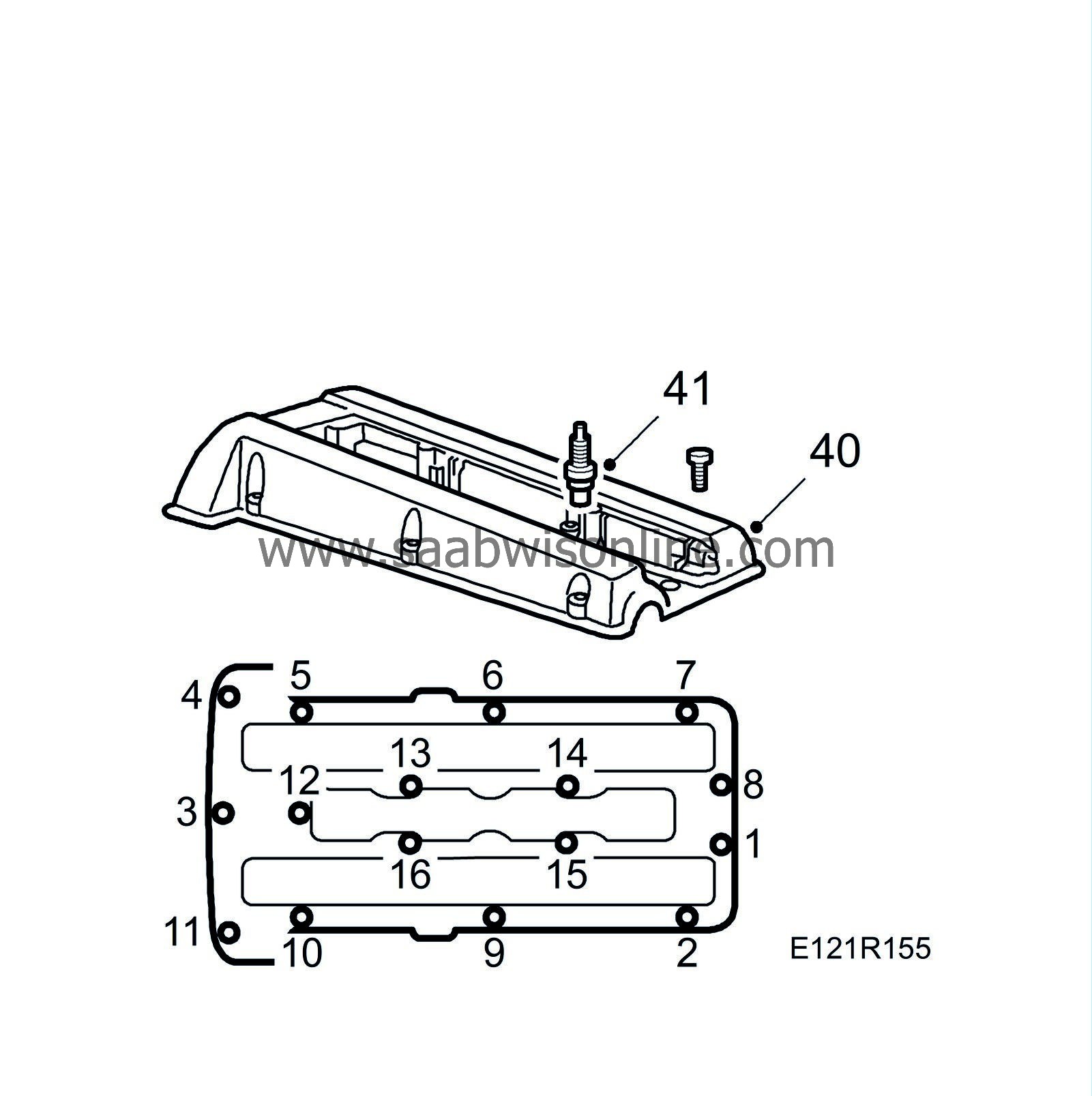
Remove the camshaft cover.
|
|
10.
|
Raise the car and remove the front right wheel.
|
|
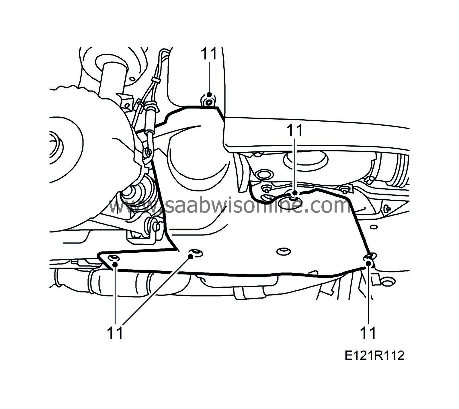
11.
|
Remove the right-hand belt circuit cover.
|
|
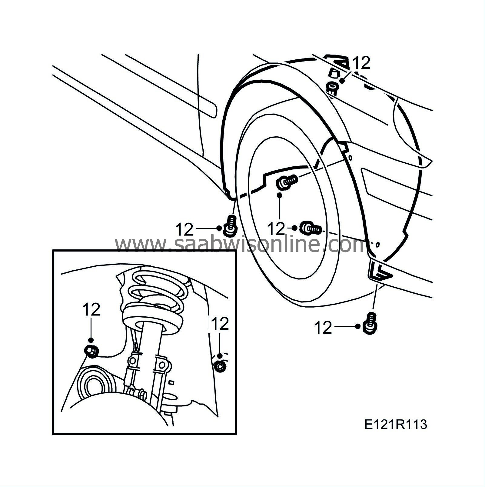
12.
|
Remove the right-hand wing liner.
|
|
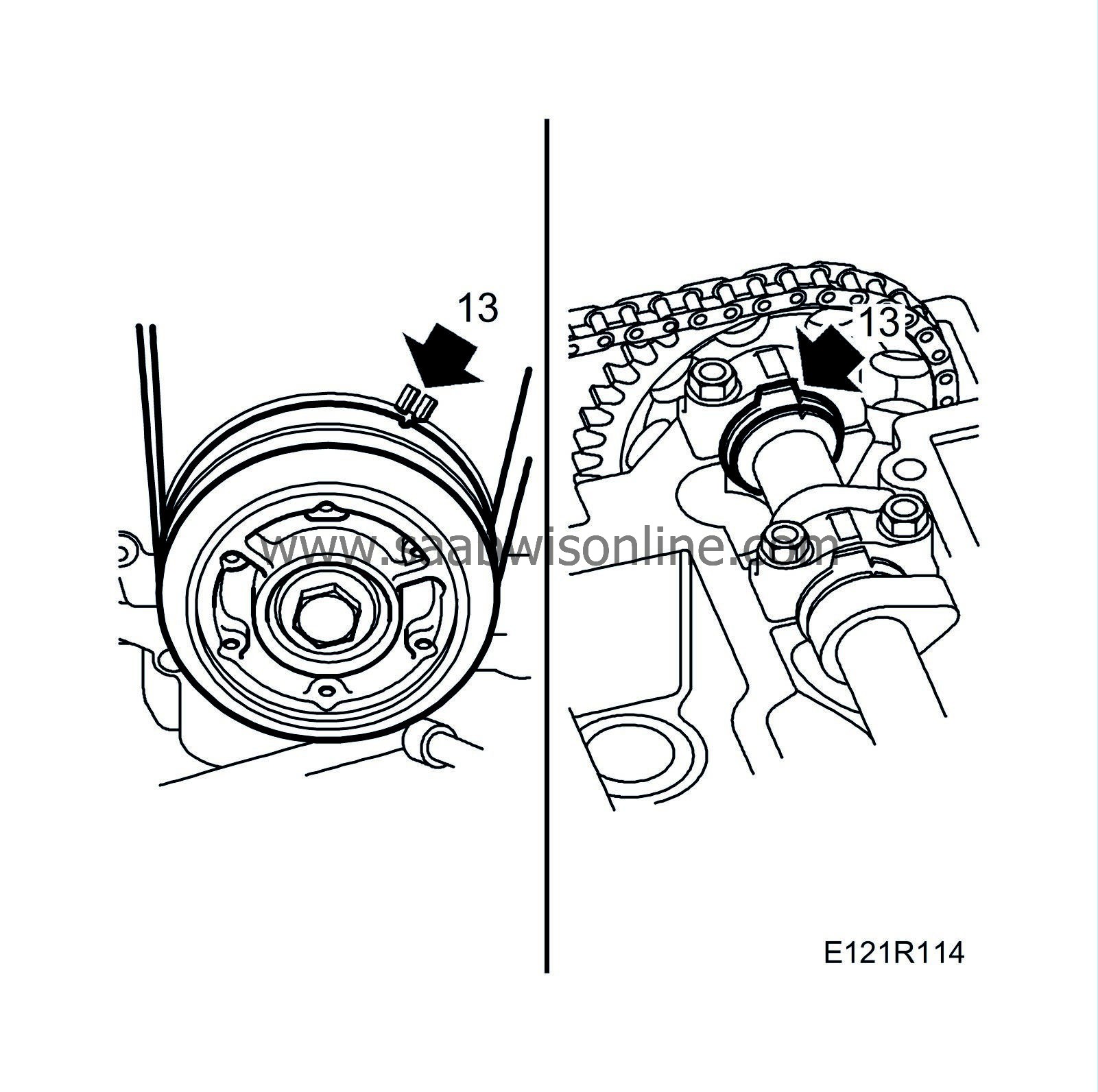
13.
|
Zero the engine by turning the crankshaft in the engine's direction of rotation until the timing marks on the pulley and timing cover are aligned.
|
|
14.
|
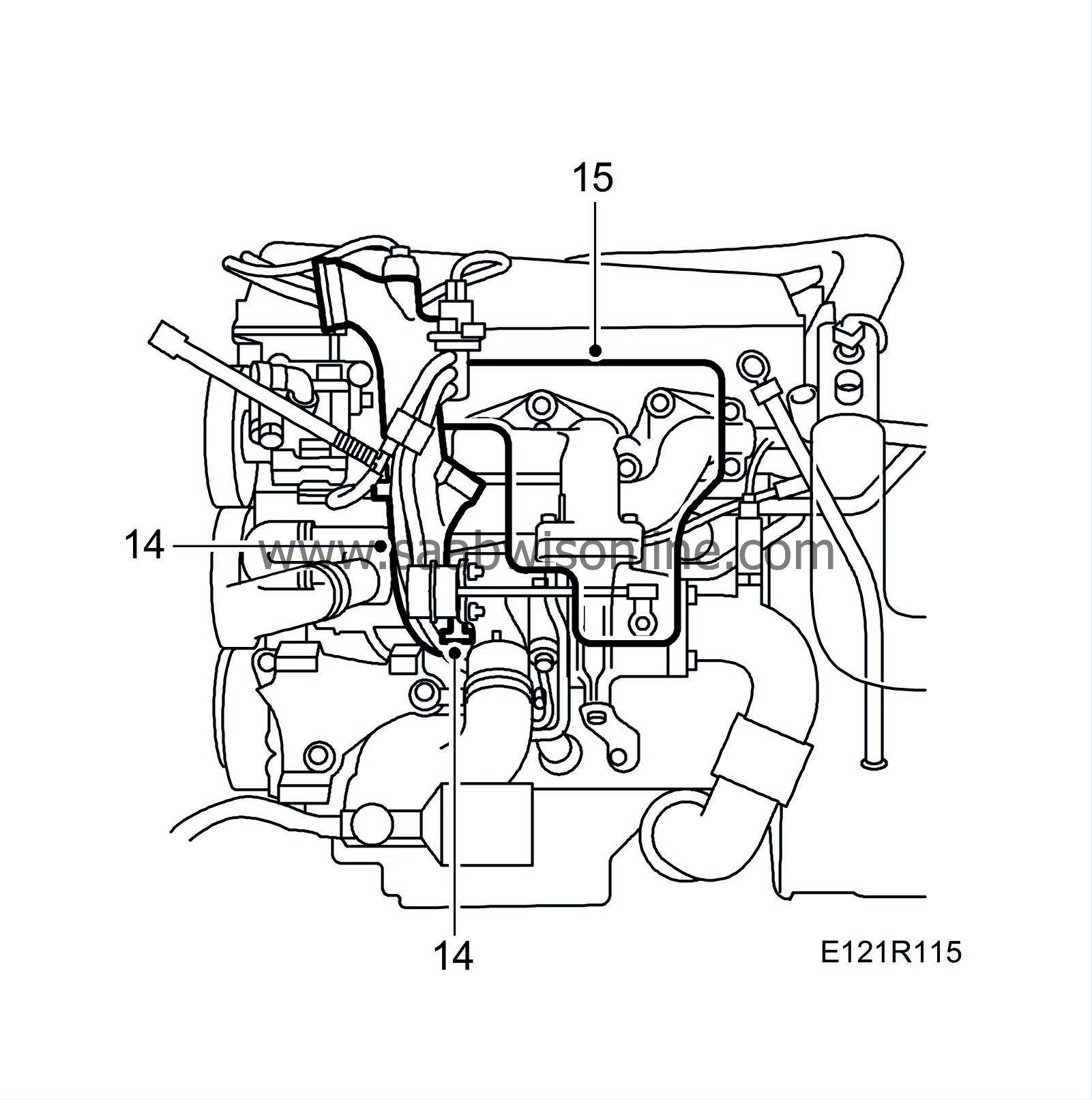
Remove the engine lifting eye and the turbocharger intake pipe and solenoid valve.
|
|
15.
|
Remove the turbocharger heat shield.
|
|
16.
|
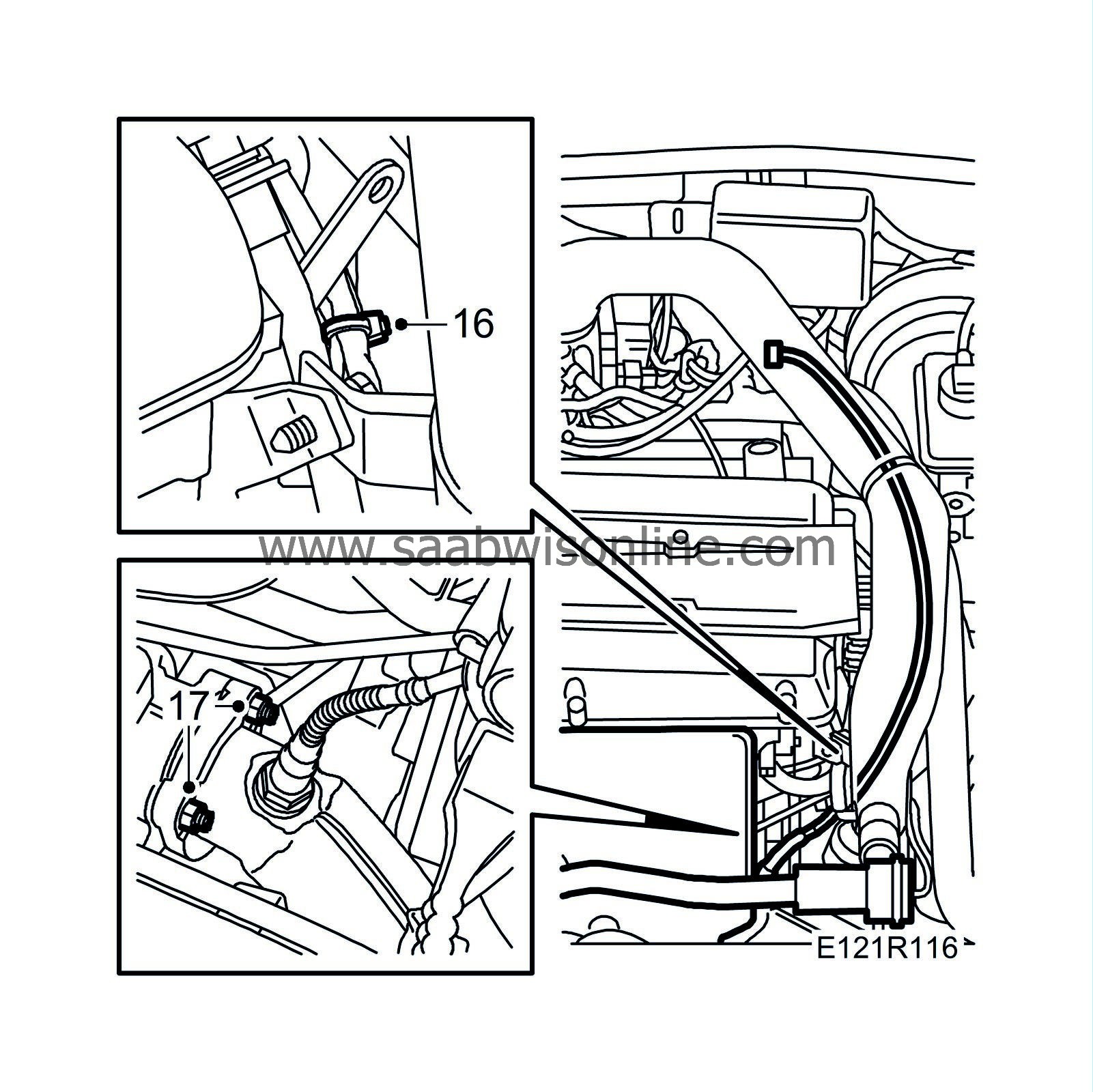
Remove the oxygen sensor connector and the cable tie.
|
|
17.
|
Remove the two upper nuts on the front exhaust pipe.
|
|
18.
|
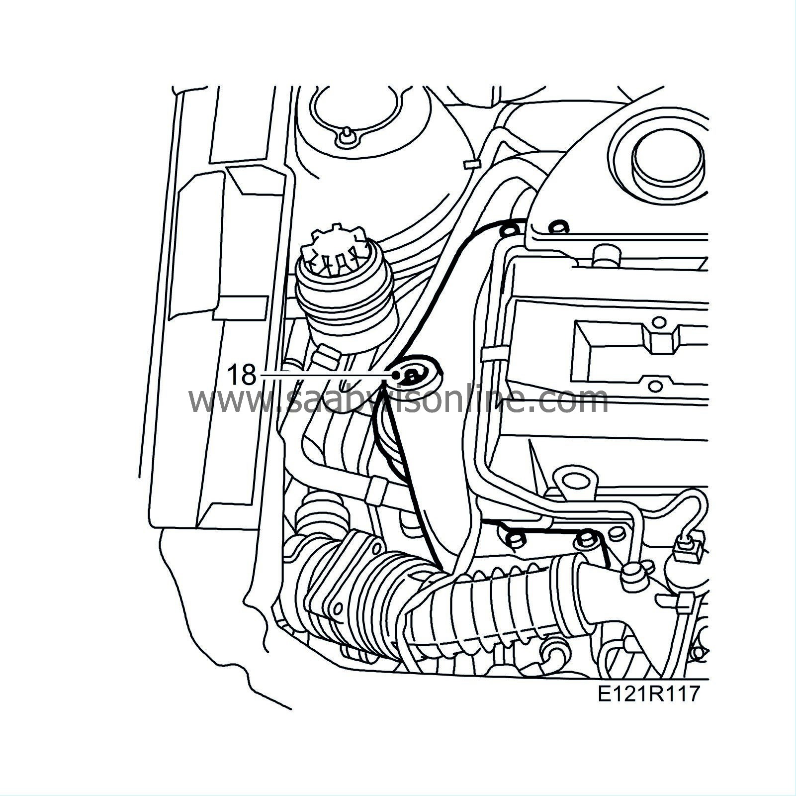
Remove the nut from the right-hand engine pad.
|
|
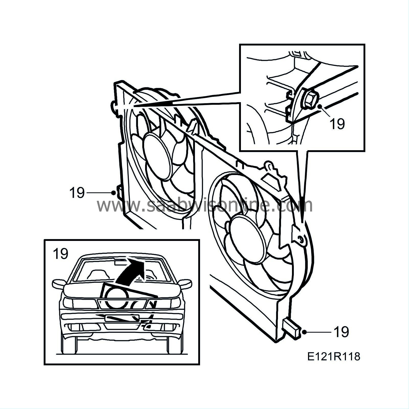
19.
|
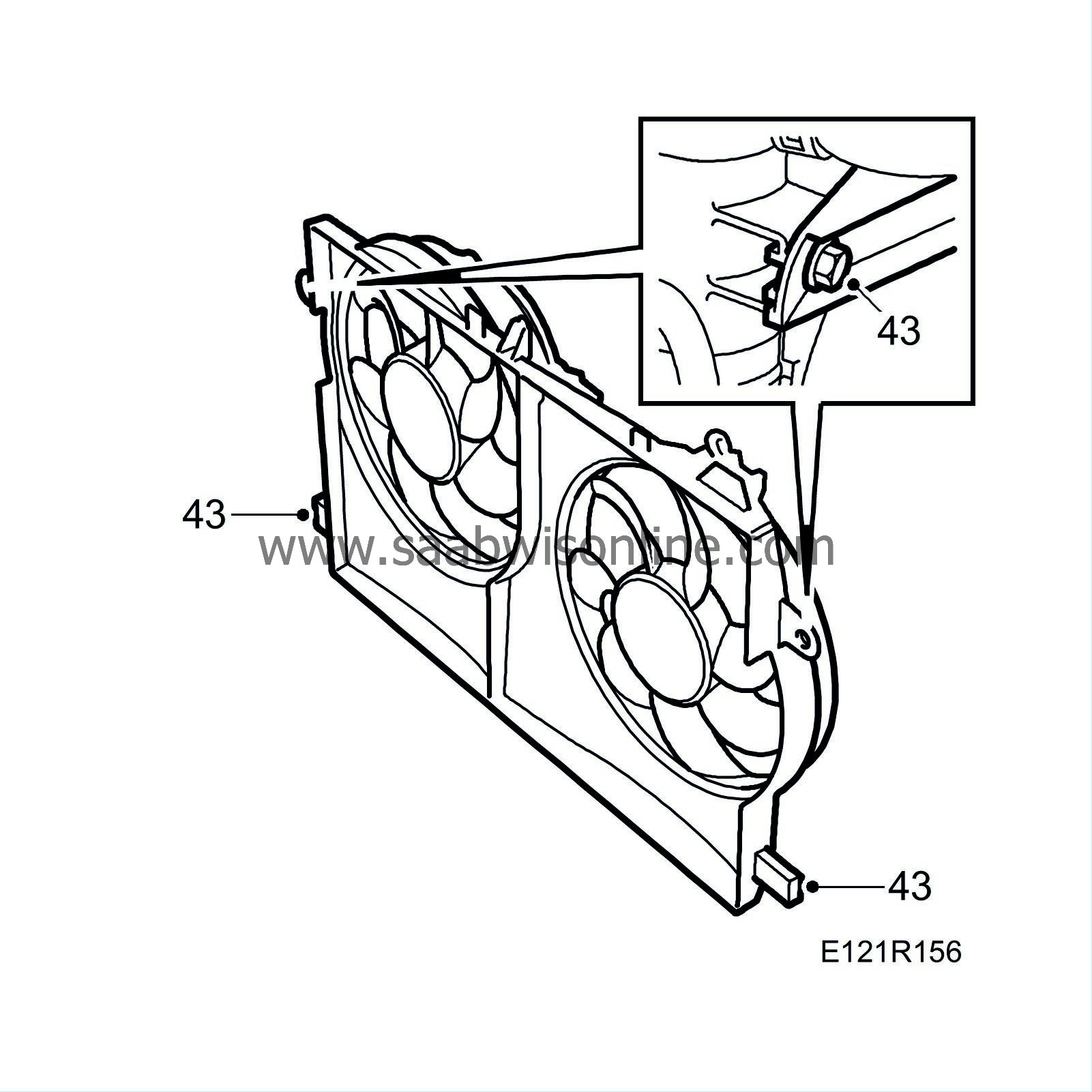
Remove the fan cowling.
|
|
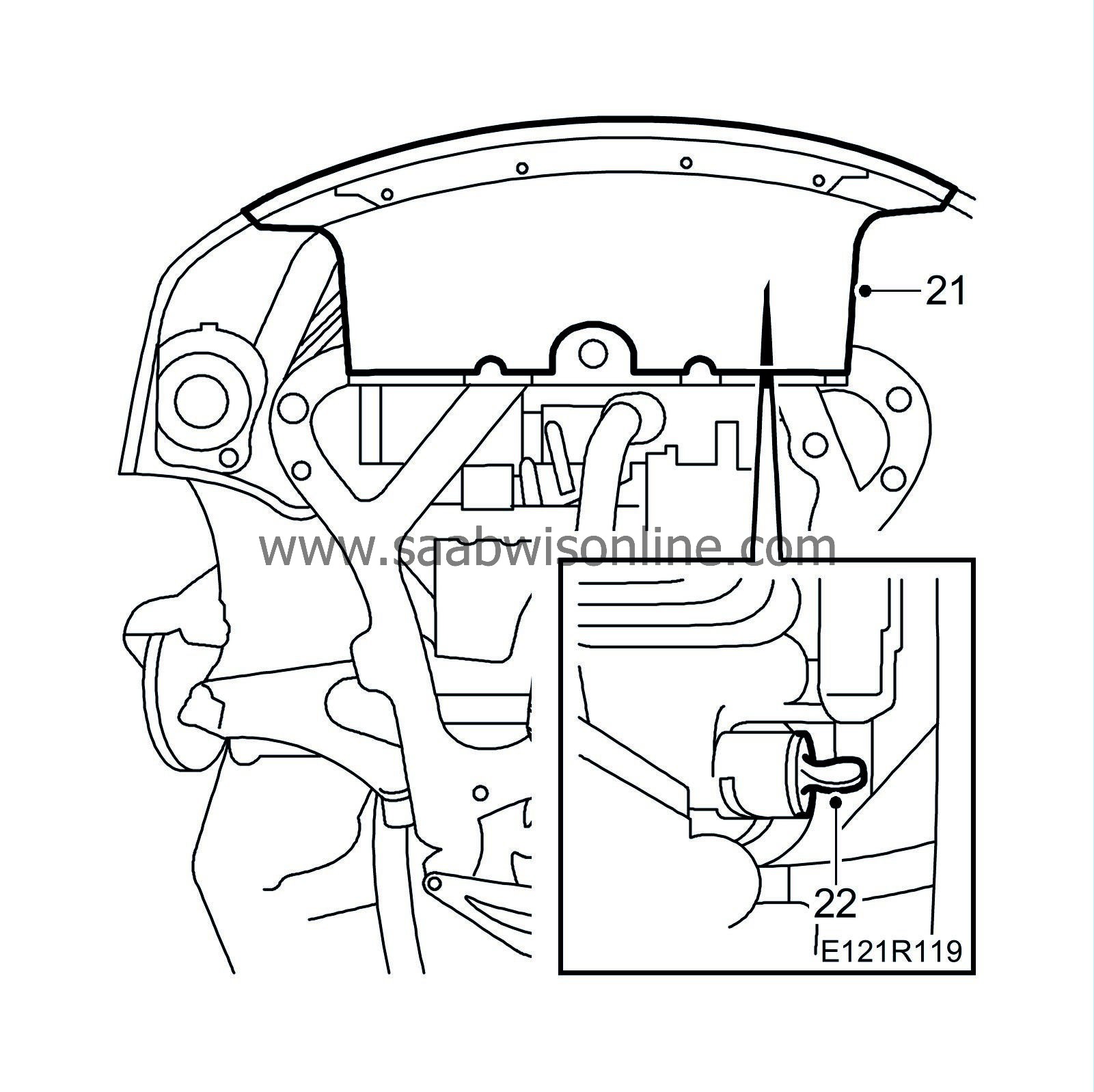
21.
|
Remove the front spoiler shield.
|
|
22.
|
Drain off the coolant.
|
|
23.
|
Position a receptacle under the car and drain the engine oil.
|
|
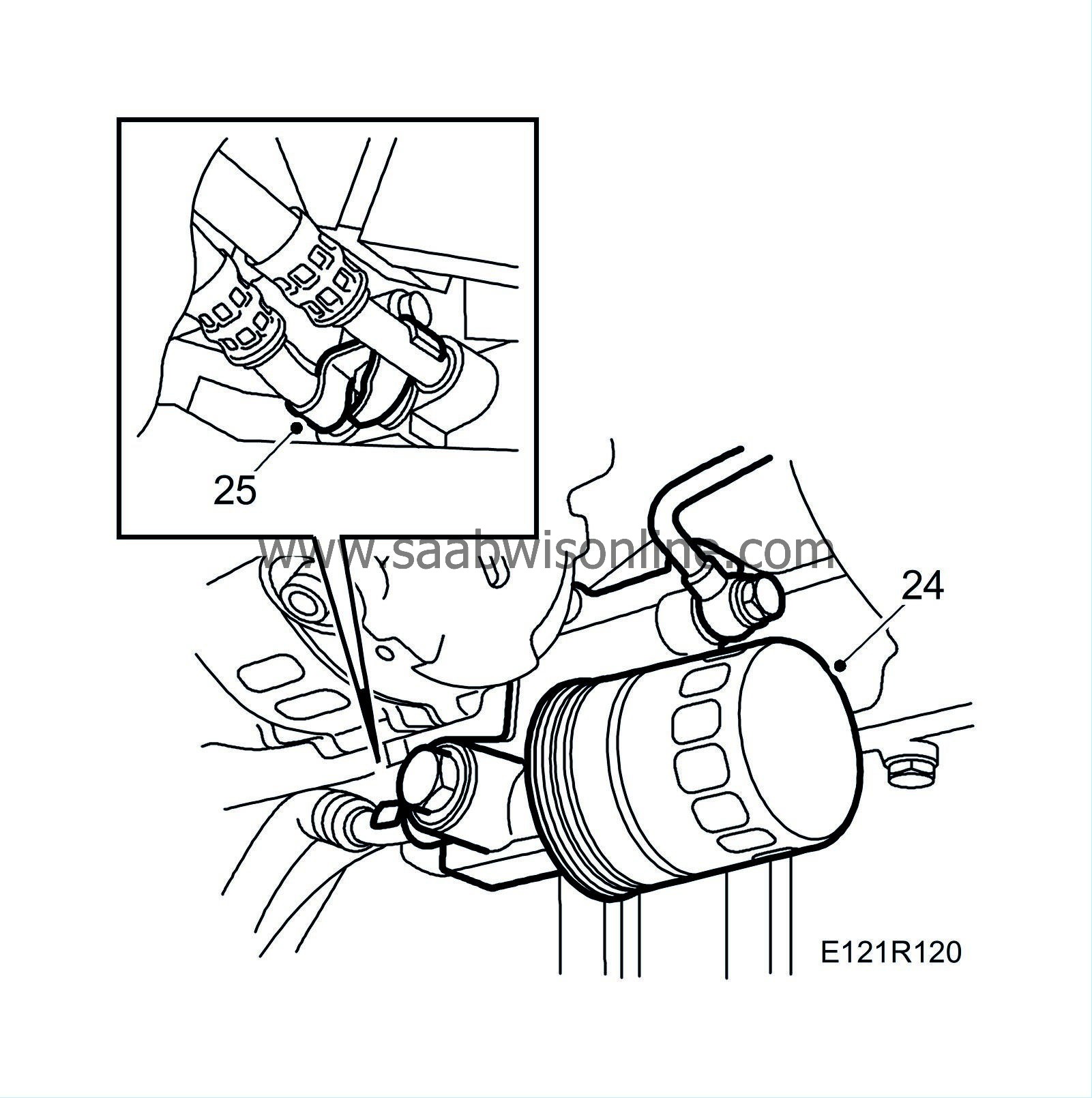
24.
|
Remove the oil filter.
|
|
25.
|
Undo the oil pipe on the oil filter adapter housing.
|
|
26.
|
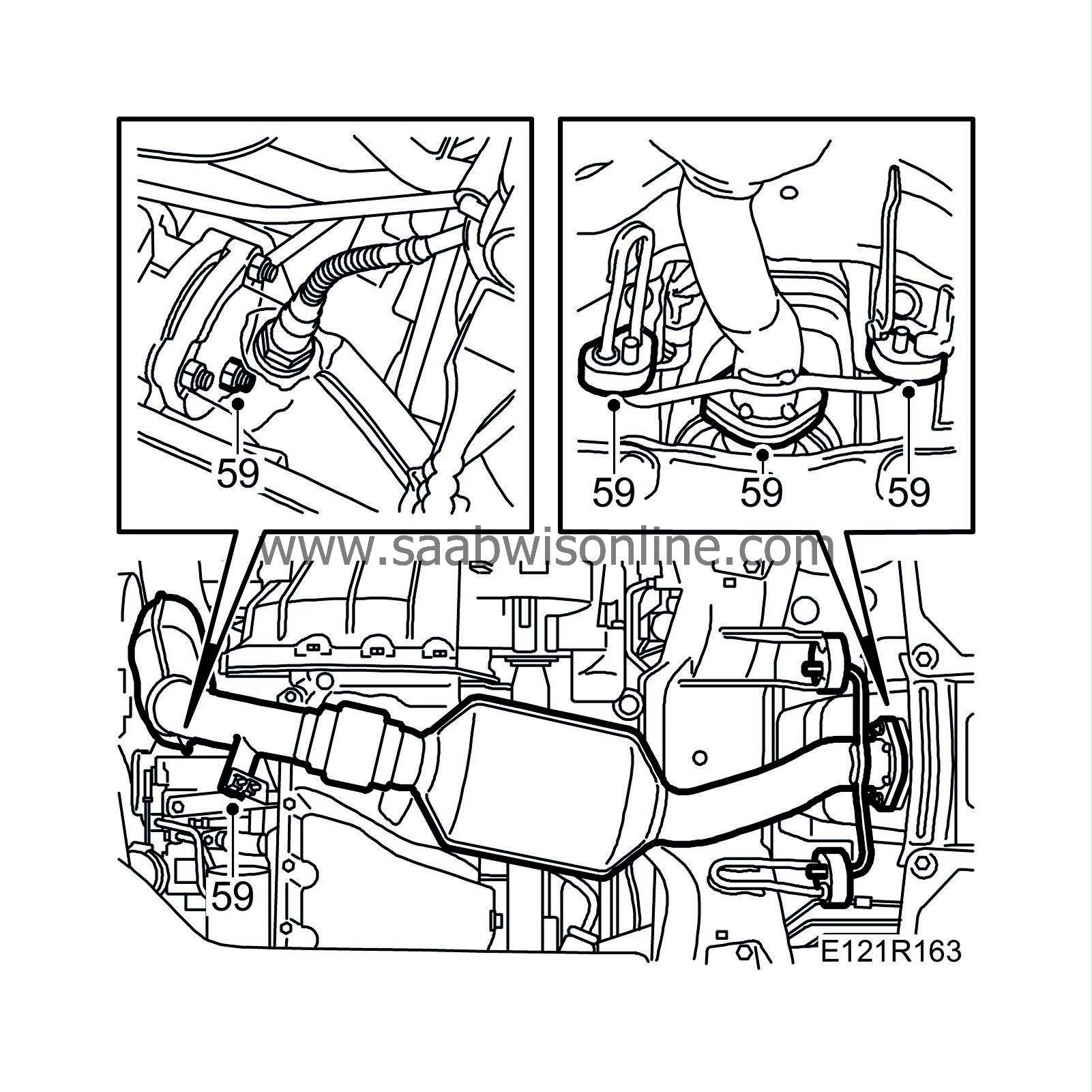
Remove the front exhaust pipe.

|
|
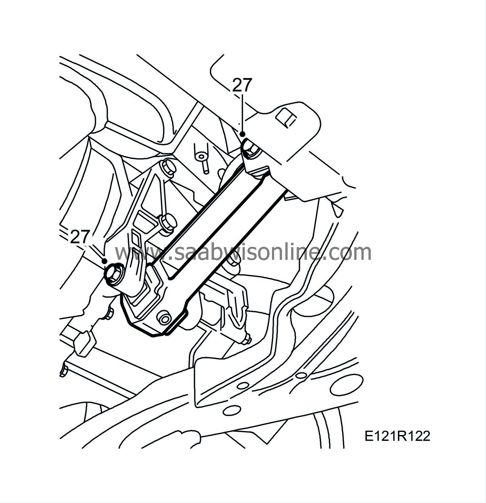
27.
|
Remove the front torque arm.
Front bracket with through bolt:
Remove from below.
Other:
Remove from above.
Cars with rear torque arm:
Remove the torque arm.
|
|
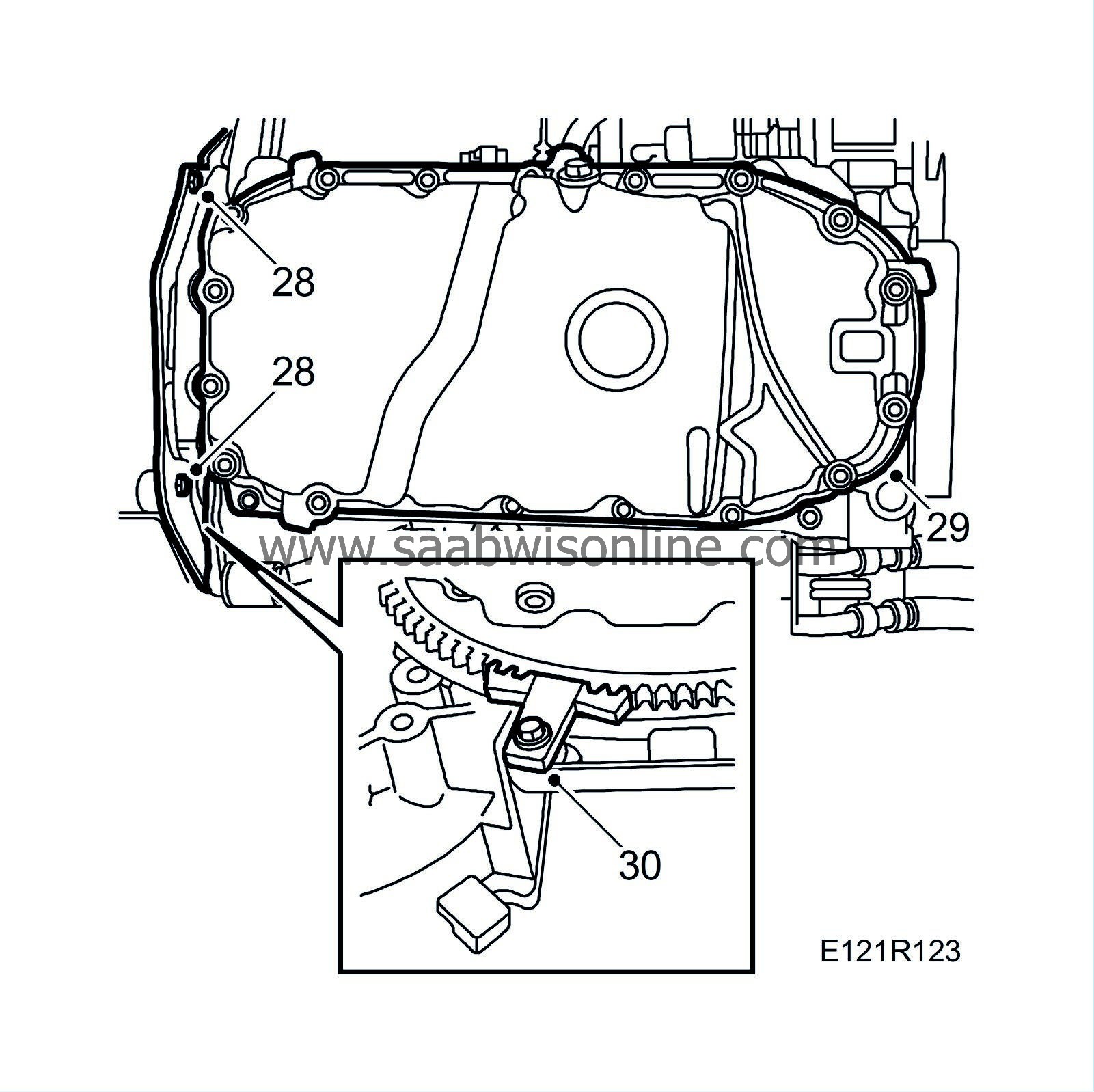
28.
|
Remove the protective cover between the engine and gearbox.
|
|
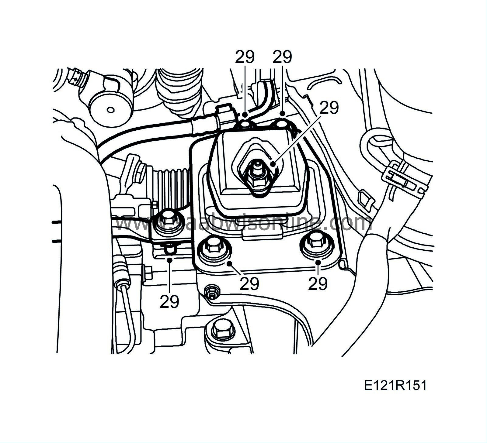
29.
|
Detach the crankcase ventilation hose and remove the oil sump. Raise the engine slightly using a column jack. Place a wooden block in between.
|
|
31.
|
Lower the car and position a jack under the engine and raise it slightly at the AC compressor. Place a wooden block in between.
|
|
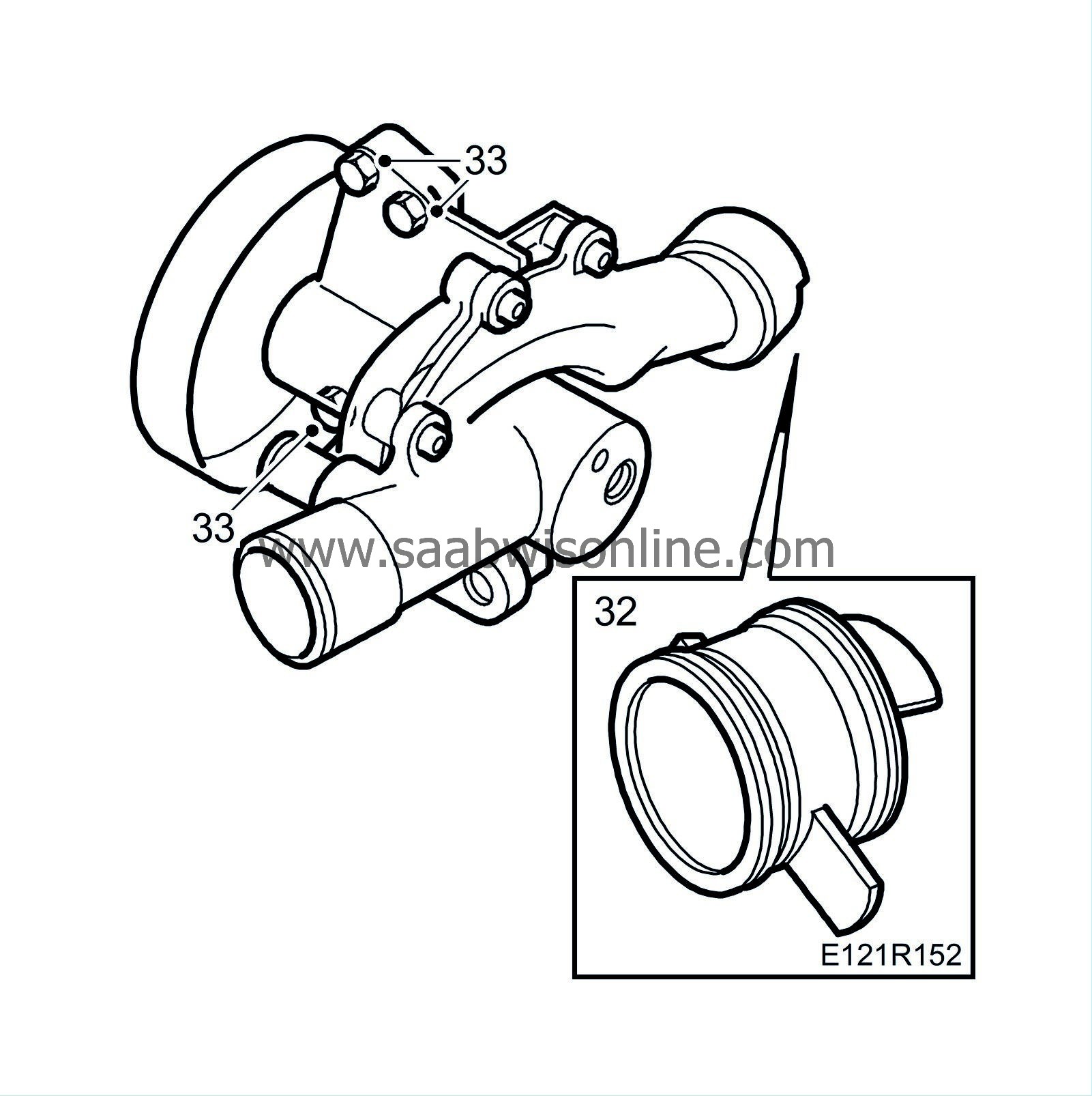
32.
|
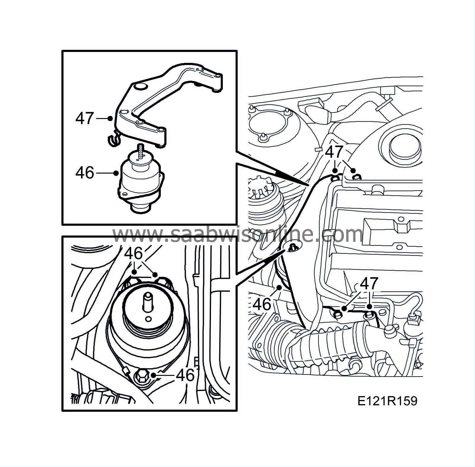
Remove the right-hand engine mounting bracket and the engine pad.

|
|
33.
|
Fit
83 95 238 Wedges
between the oil filter adapter and subframe, and between the inner drive shaft universal joint and subframe, and lower the engine.
|
Note
|
|
Be careful not to damage the drive shaft universal joint gaiter.
|
|
|
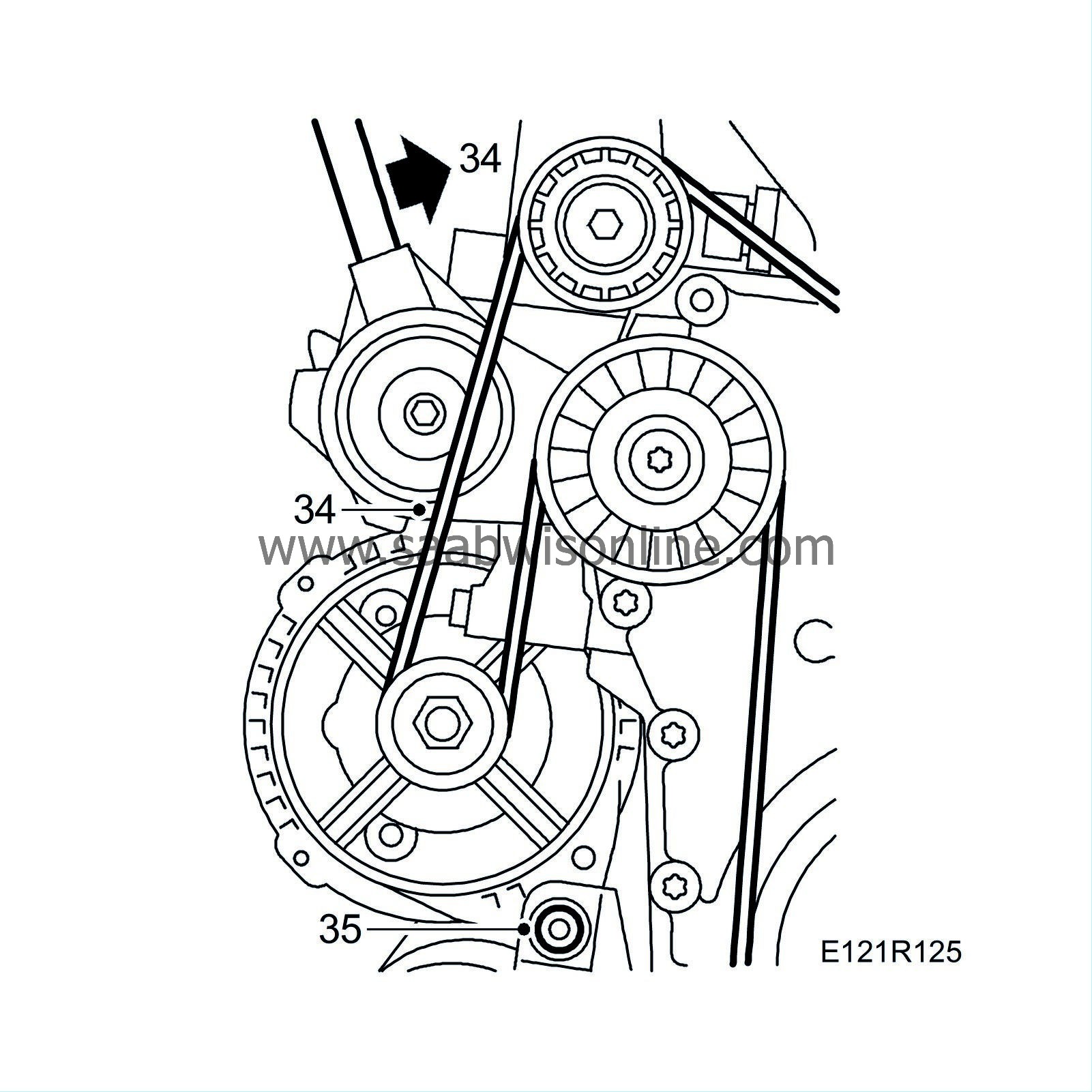
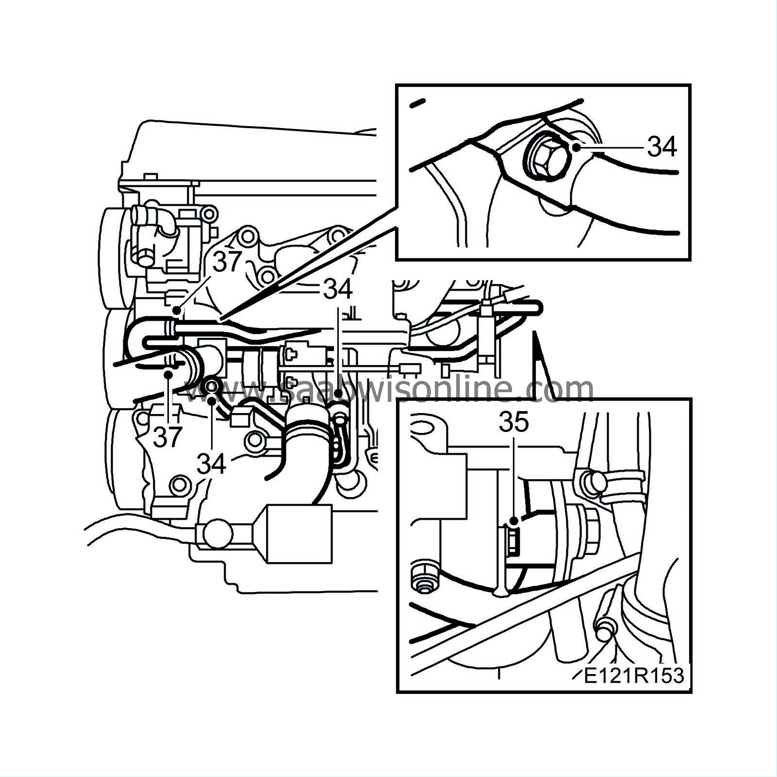
34.
|
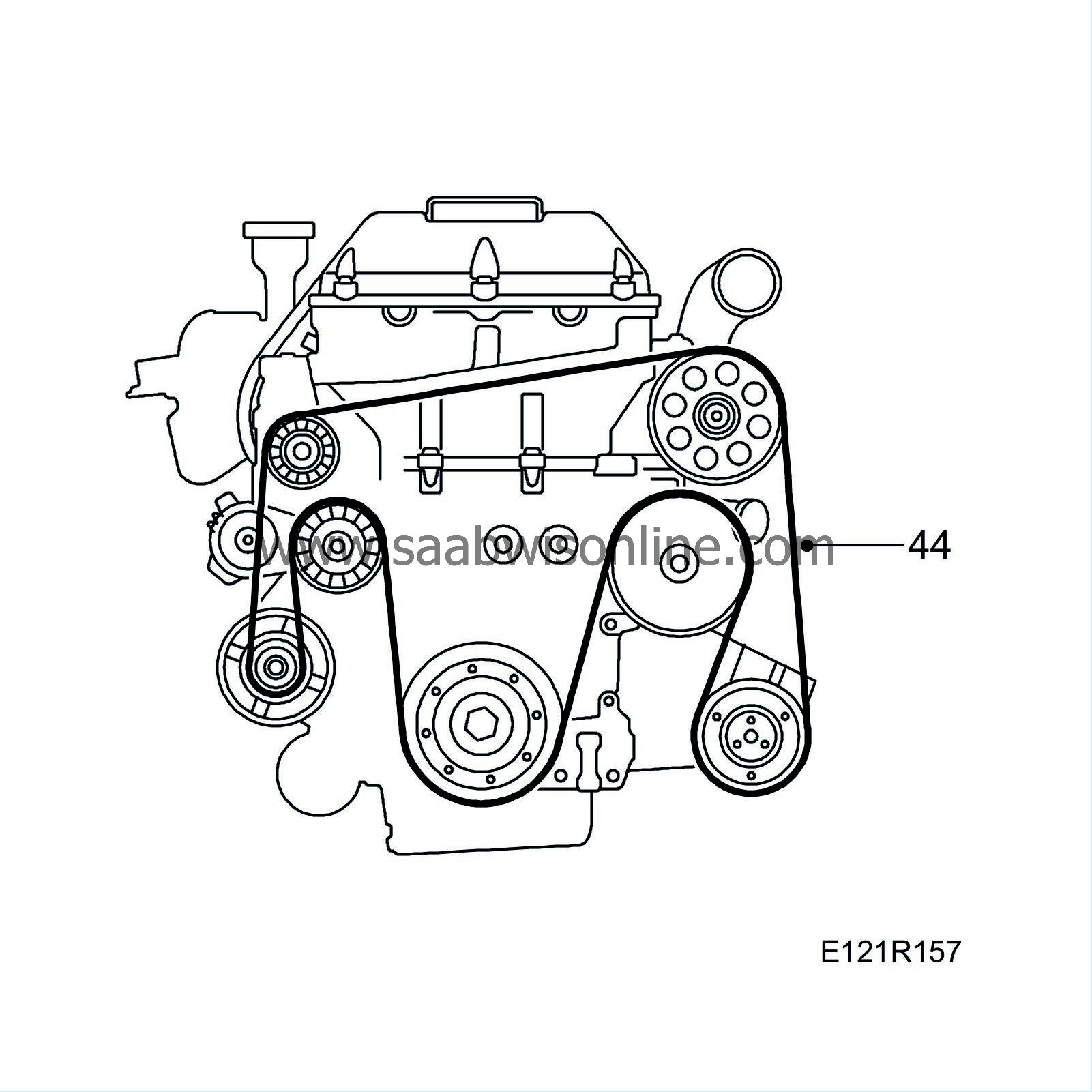
Unload the belt tensioner and remove the multigroove belt.
|
|
35.
|
Remove the generator's lower bolt and the outer lower bolt which screws into the timing cover on the intermediate shaft bearing bracket.
|
|
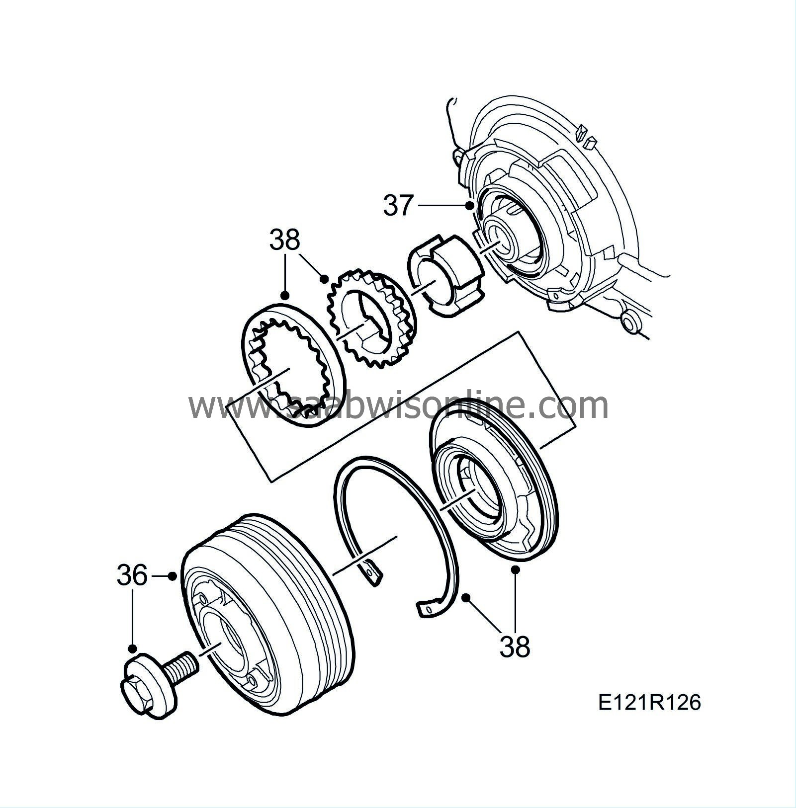
36.
|
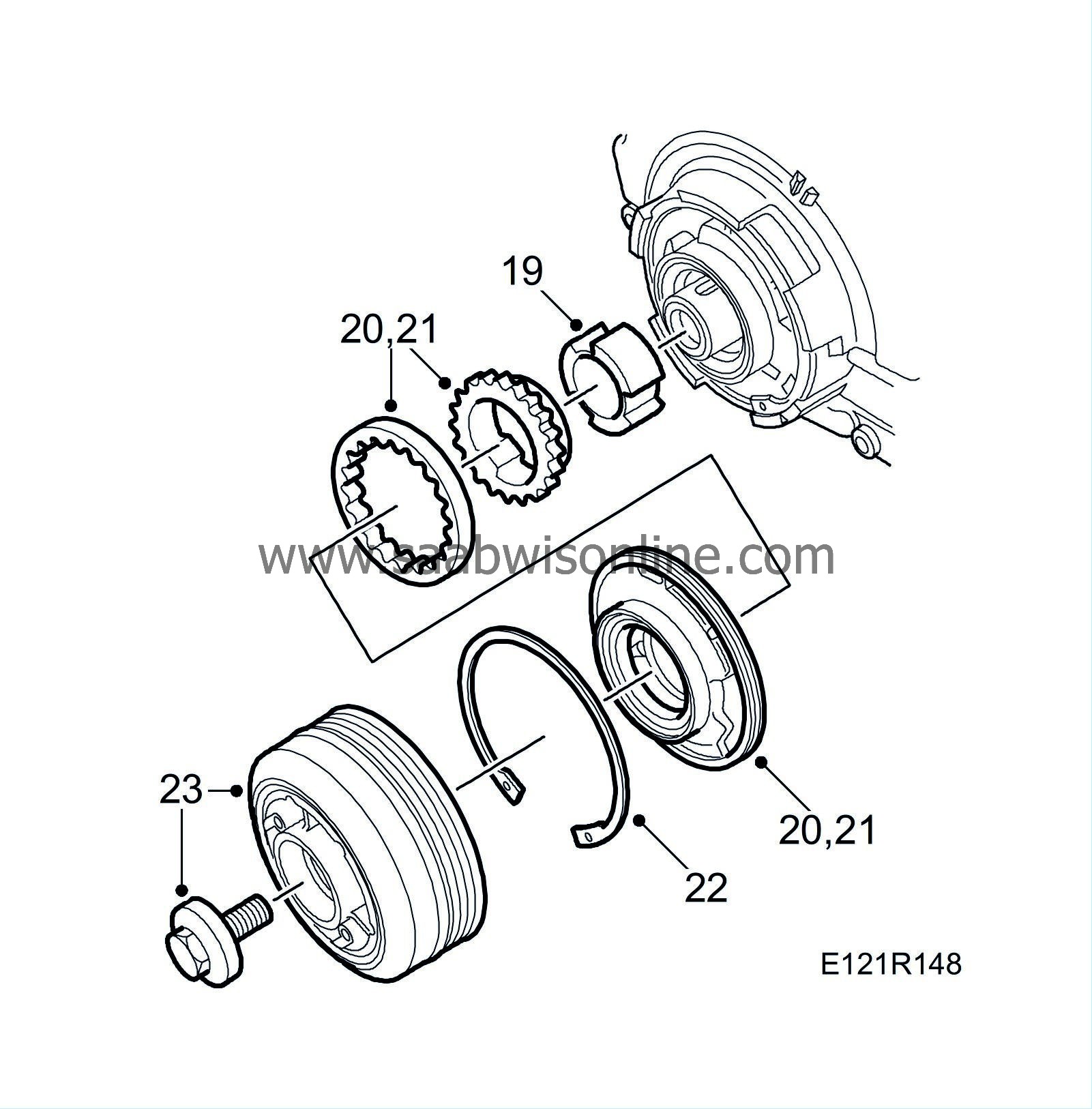
Remove the crankshaft pulley.
|
Note
|
|
Check that the timing cover marking corresponds with the pulley before it is lifted off.
|
|
|
37.
|
Remove the crankshaft seal.
|
|
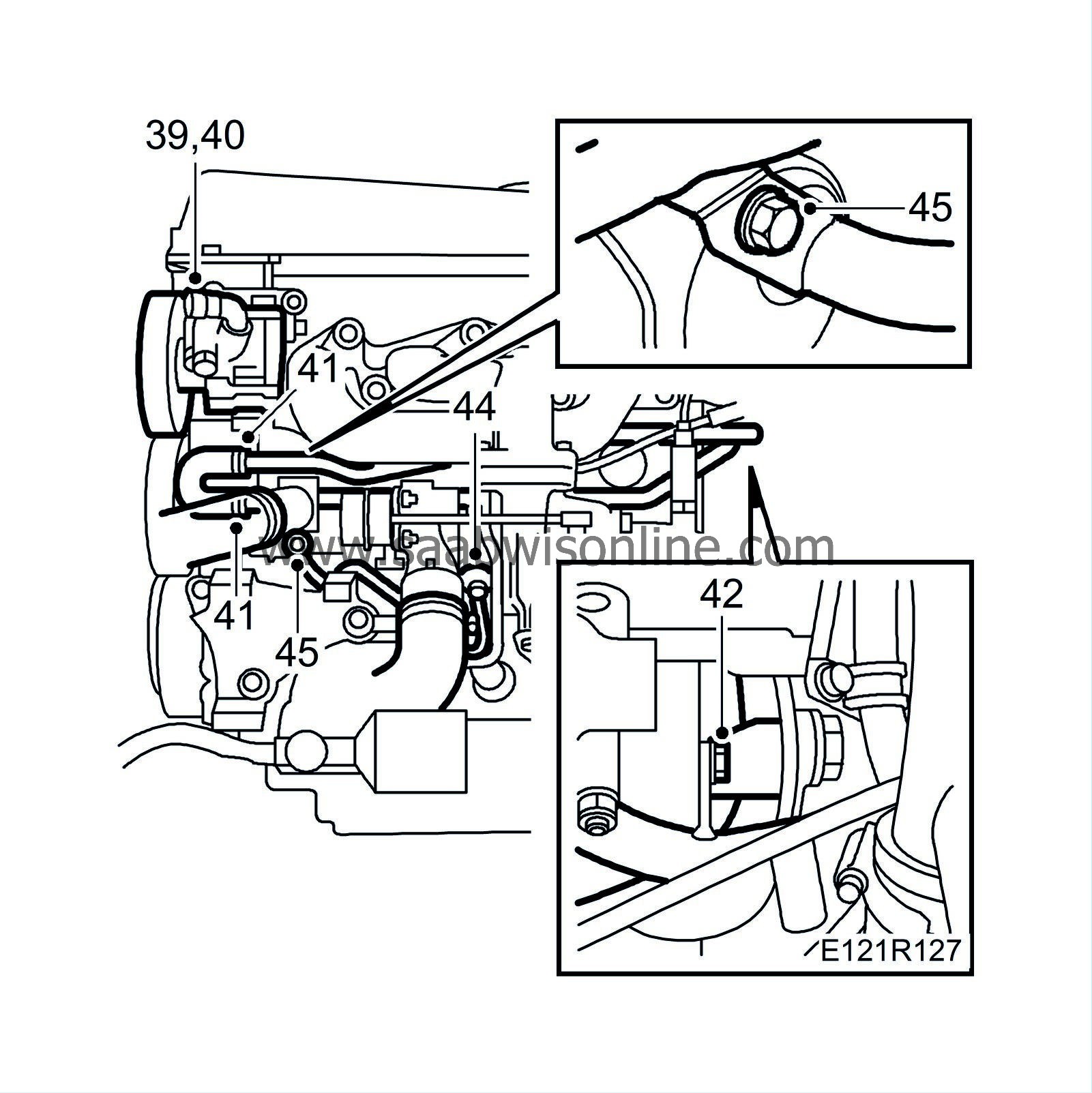
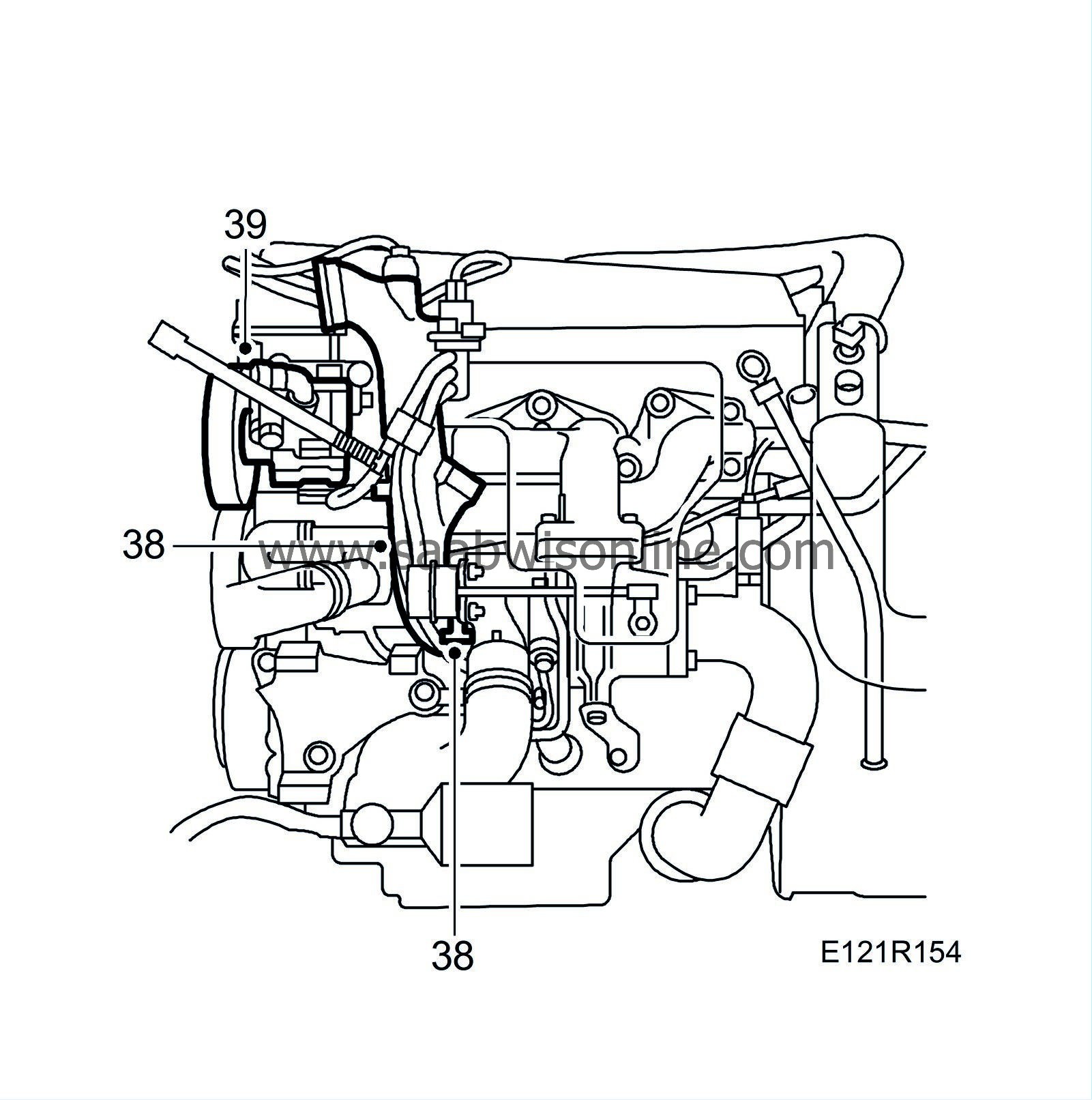
39.
|
Remove the power steering pump from the bracket and move it aside.
|
|
40.
|
Remove the power steering pump mounting bracket.
|
|
41.
|
Remove the hose clips and hoses on the coolant pump inlet.
|
|
42.
|
Detach the two longitudinal coolant pipes from the engine block.
|
|
43.
|
Detach the two longitudinal coolant pipes from the coolant pump.
|
|
44.
|
Undo the coolant pipe bolt slightly (at the turbocharger) from the coolant pump.
|
|
45.
|
Remove the coolant pipe from the coolant pump.
|
|
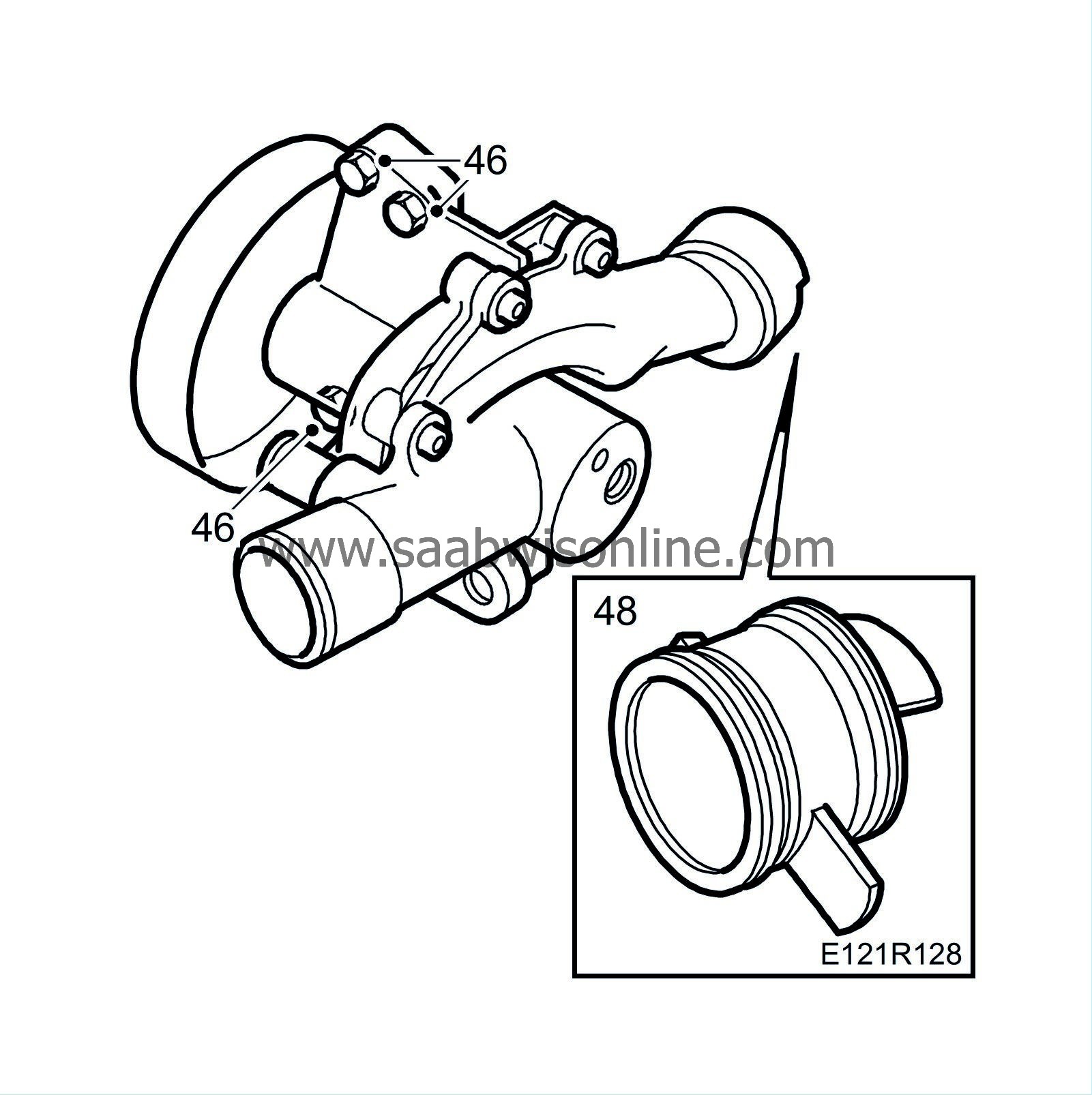
46.
|
Undo the coolant pump retaining bolts.
|
|
47.
|
Carefully work the pump free from the bracket and from the pump's connecting sleeve on the engine block.
|
|
48.
|
Remove the connecting sleeve from the cylinder block.
|
|
49.
|
Remove the AC bracket right-hand upper bolt which screws into the timing cover.

|
|
50.
|
Remove the two bolts in the subframe holding the front torque arm. (On relevant models)
|
|
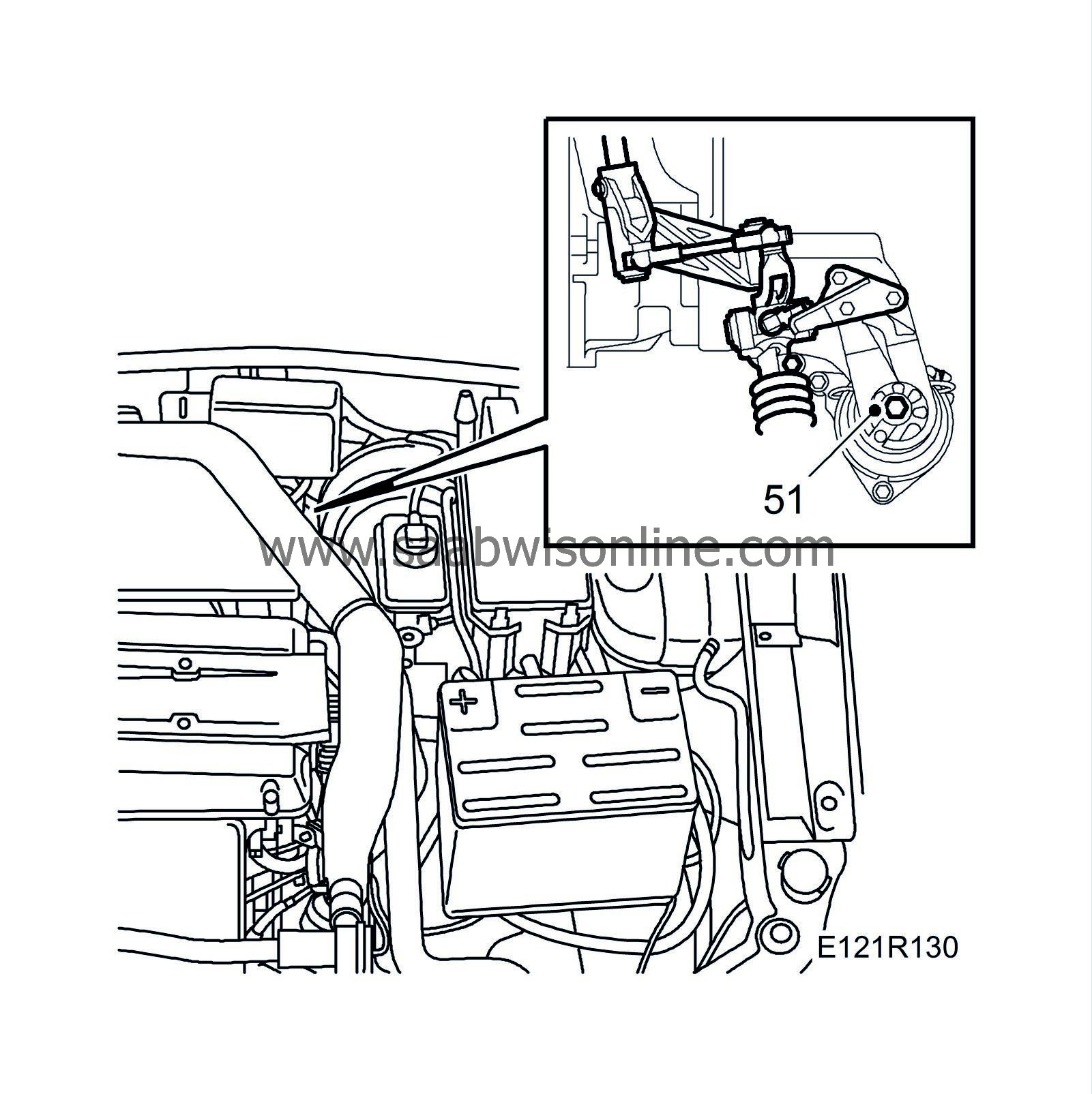
51.
|
Remove the nut on the rear engine mounting.
|
|
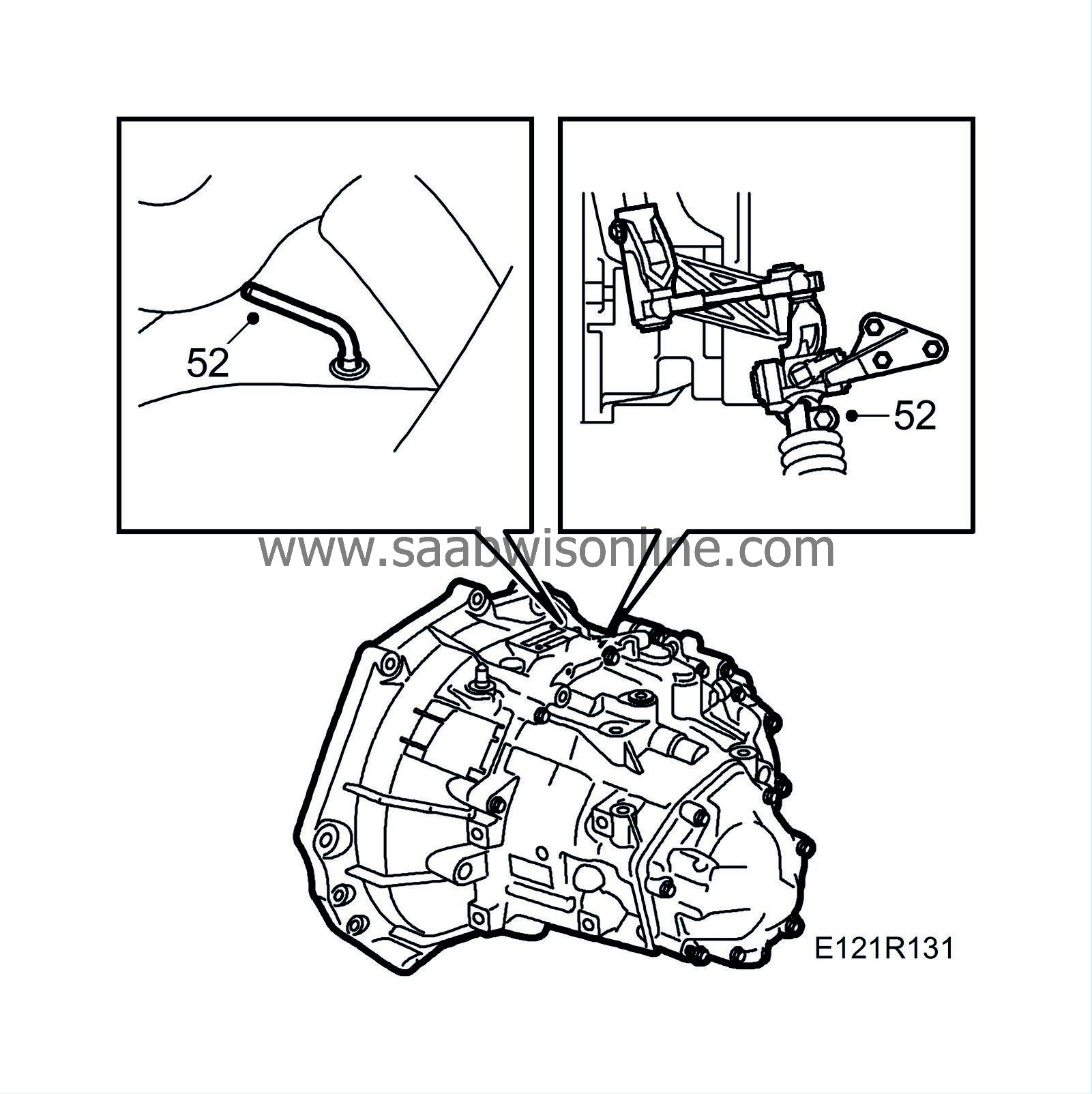
52.
|
Man:
Lock 4th gear by inserting
87 92 335 Lock pin
. Undo the clamp slightly and pull the selector rod out of the linkage.
|
|
53.
|
Unload the left-hand engine pad by positioning a jack under the gearbox.
|
|
54.
|
Remove the left-hand engine pad.

|
|
55.
|
Man:
Remove the gearbox mounting and the ground cable.
|
|
56.
|
Position a
83 95 238 Wedge
between the gearbox and subframe and lower the jack.
|
|
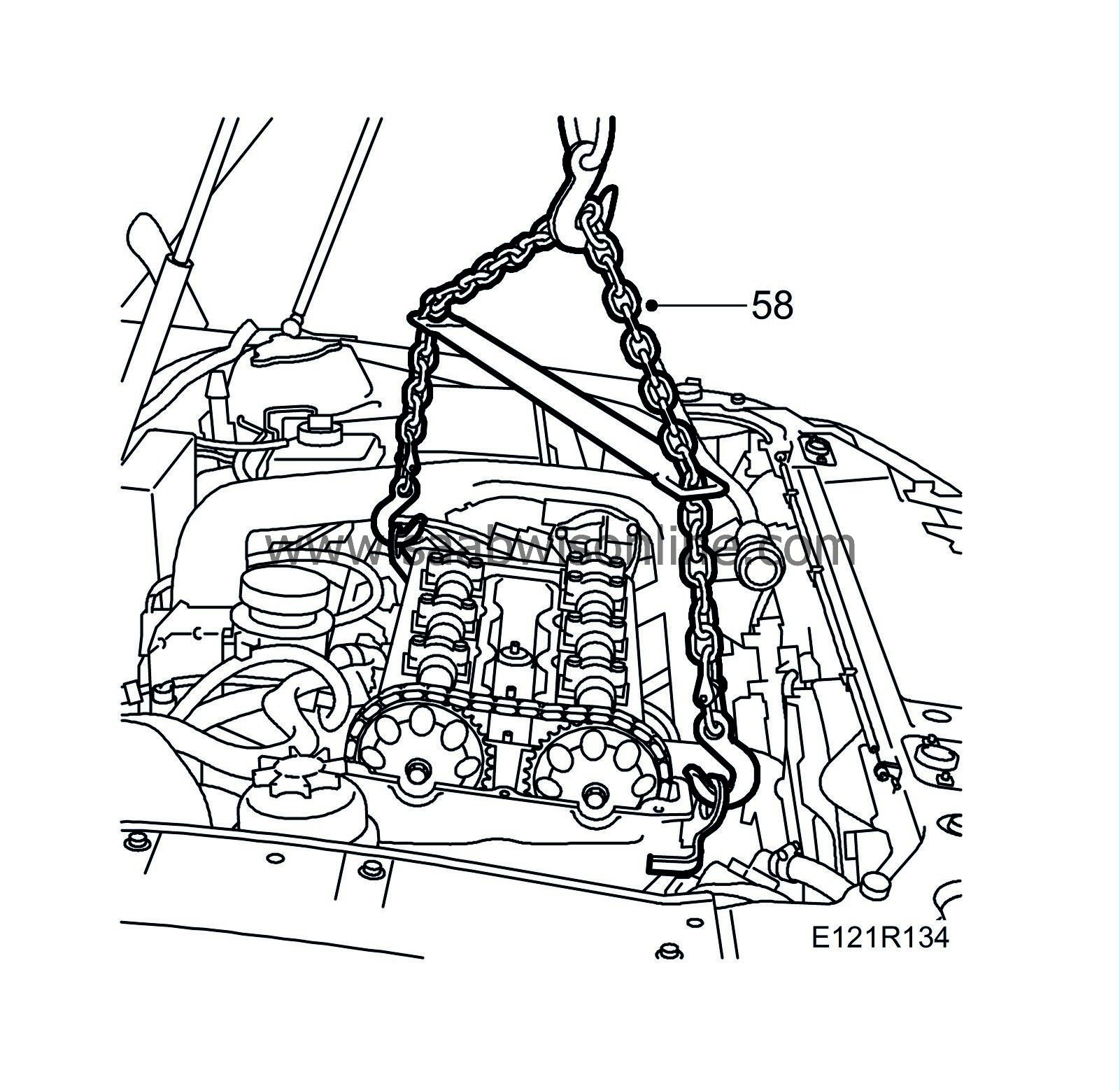
58.
|
Connect an engine lift and raise the engine.
|
|
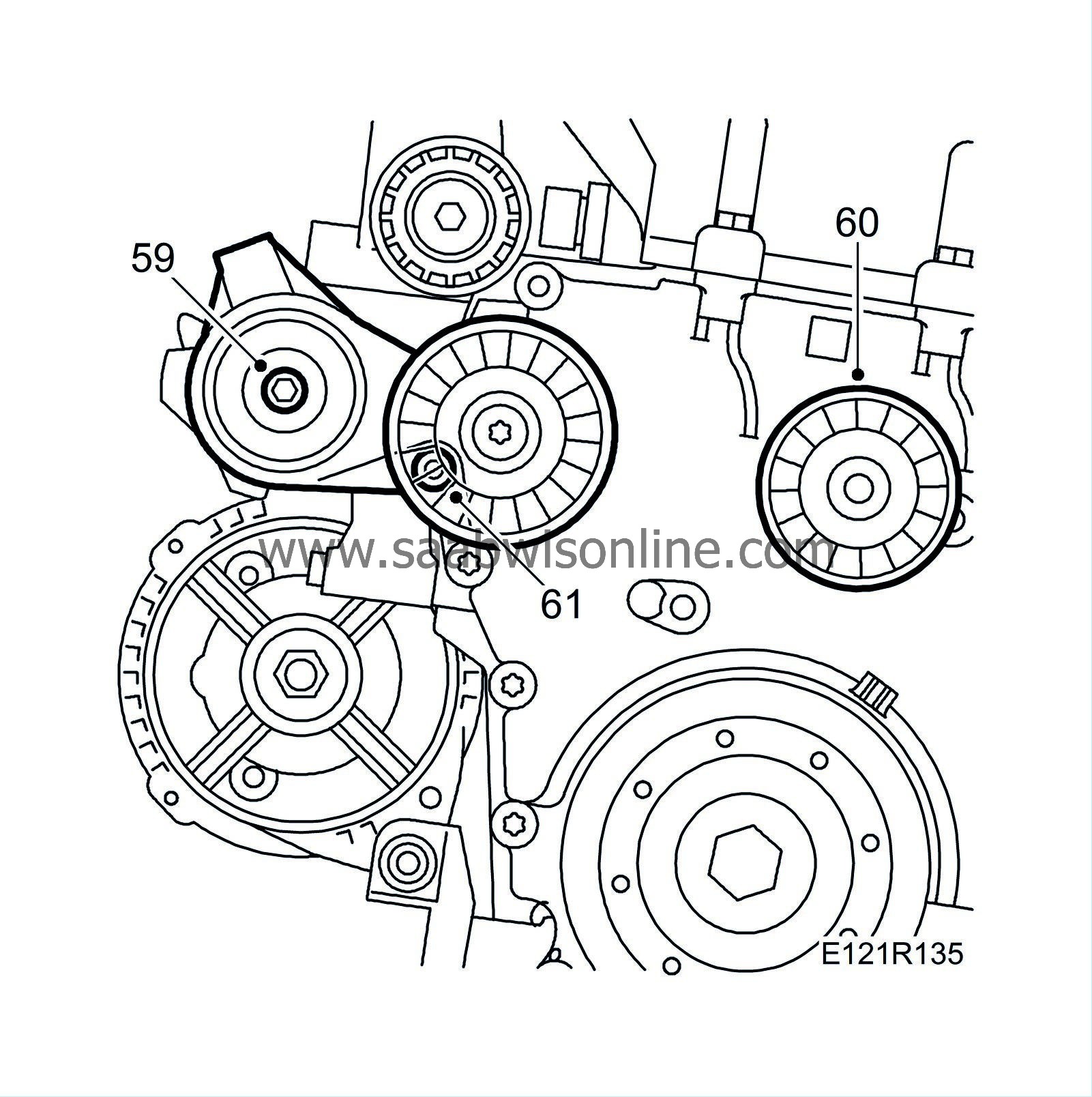
59.
|
Move the engine slightly to the left and remove the belt tensioner.
|
|
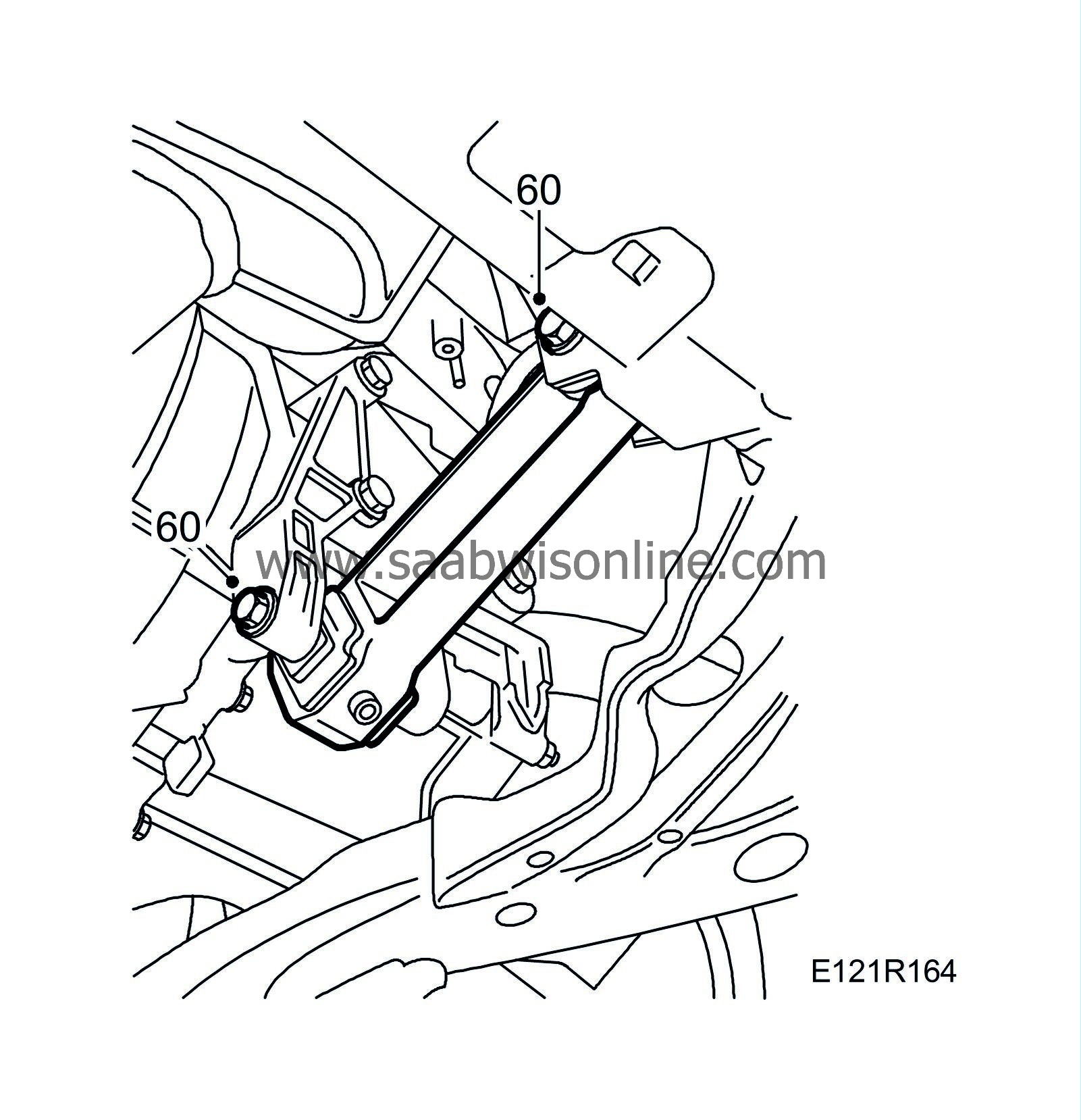
60.
|
Remove the idler pulley.
|
|
61.
|
Remove the generator upper retaining bolt. Move the generator aside.
|
|
62.
|
Remove the generator bracket.
|
|
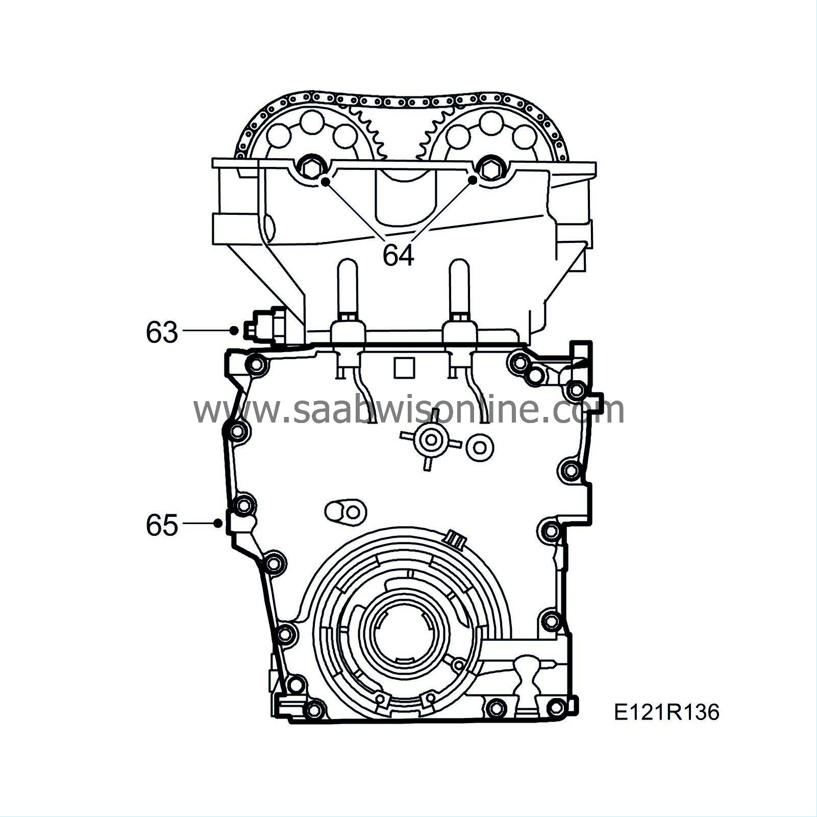
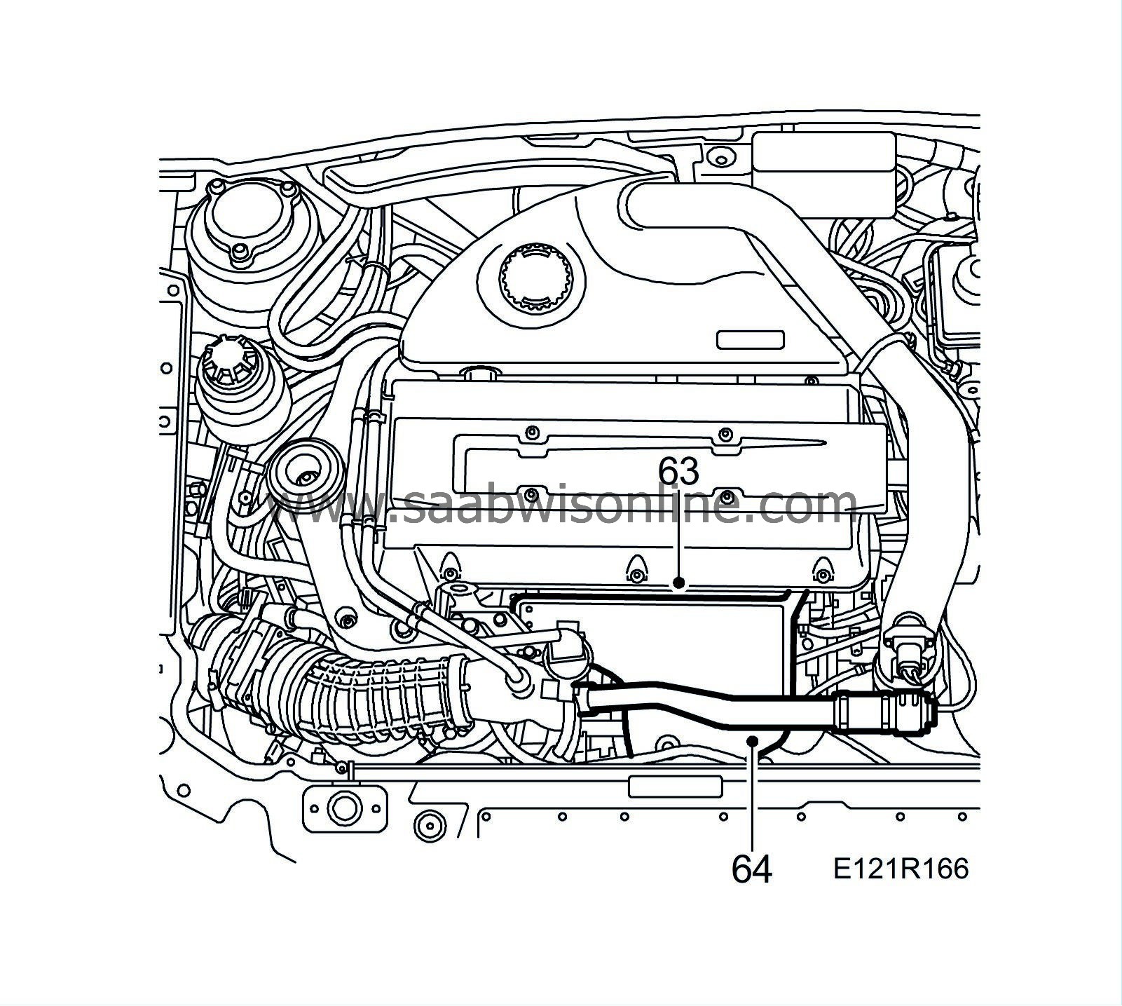
63.
|
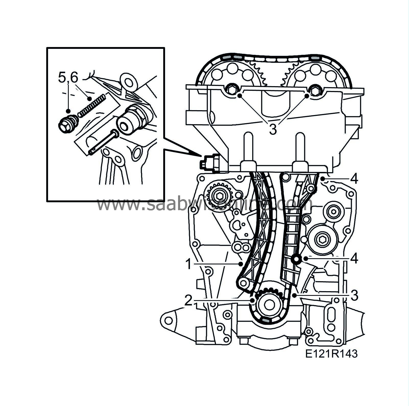
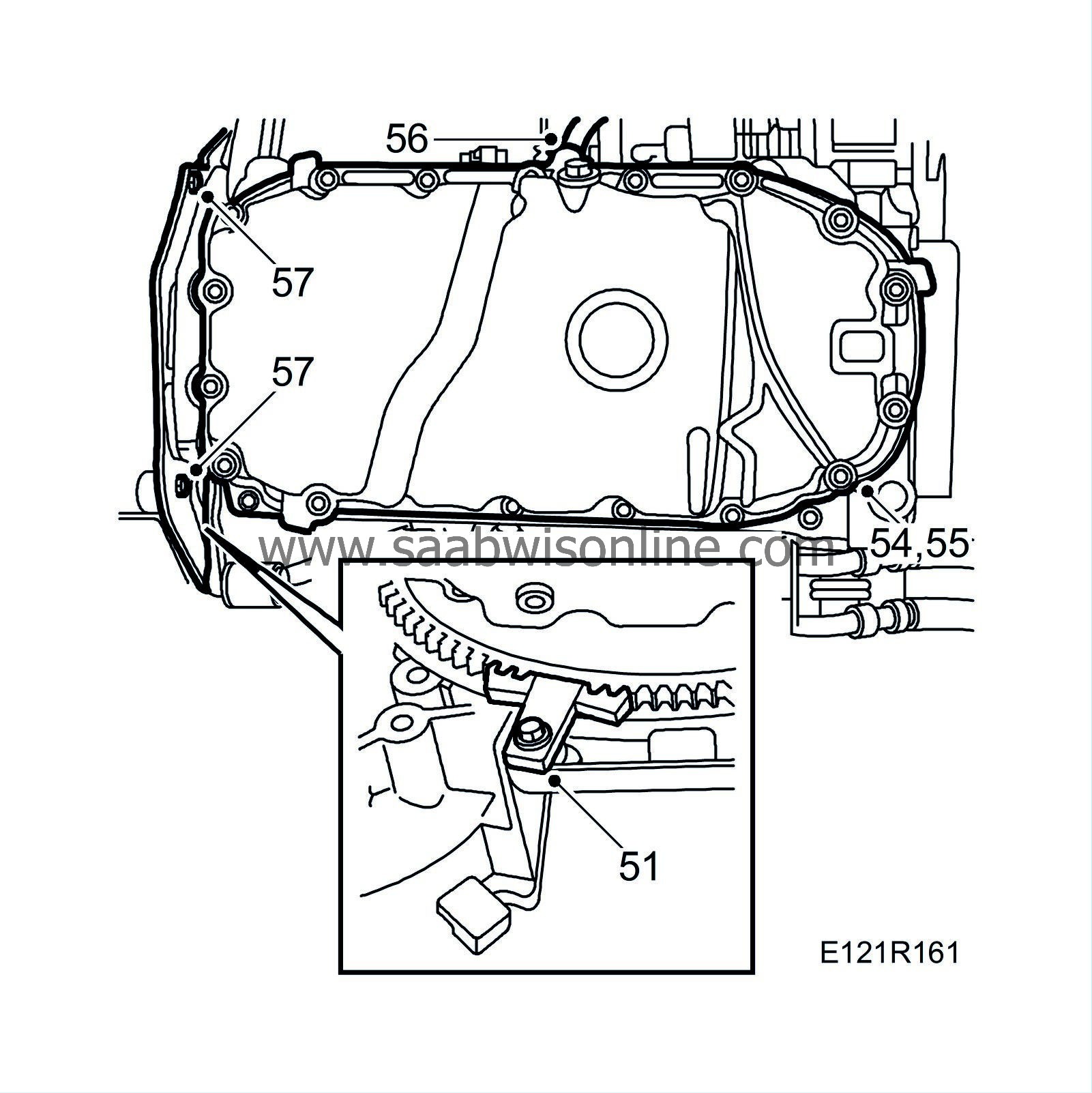
Remove the plug for the chain tensioner and the chain tensioner. Retain the spring and pin.
|
|
64.
|
Remove the camshaft sprockets.
|
|
65.
|
Remove the timing cover bolts. Move the engine to the left. Raise and lower the engine to gain access to all the bolts.
|
|
66.
|
Remove the timing cover. Move the engine to the left. Raise and lower to remove the cover.
|
Note
|
|
Be careful not to damage the cylinder head gasket.
|
|
|
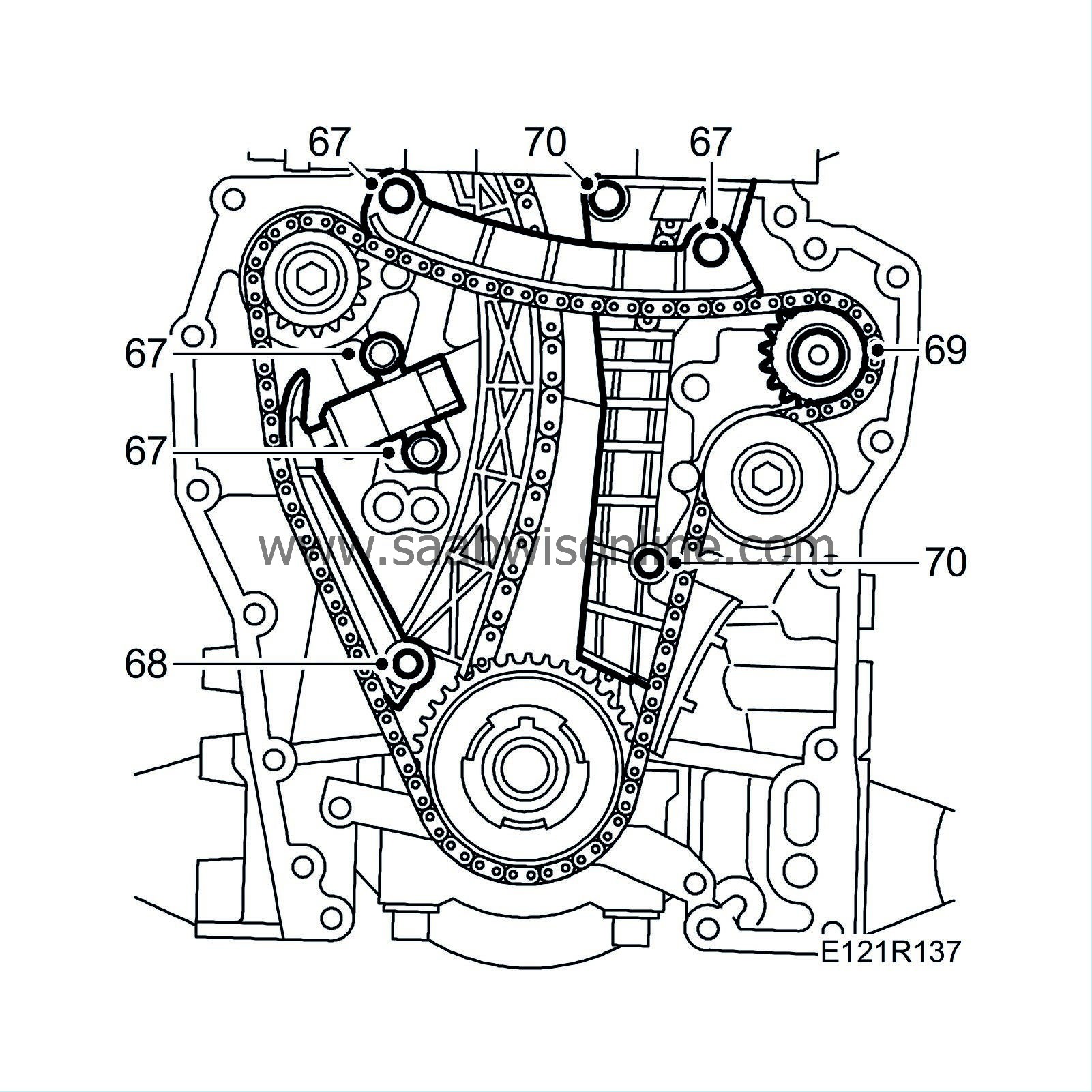
67.
|
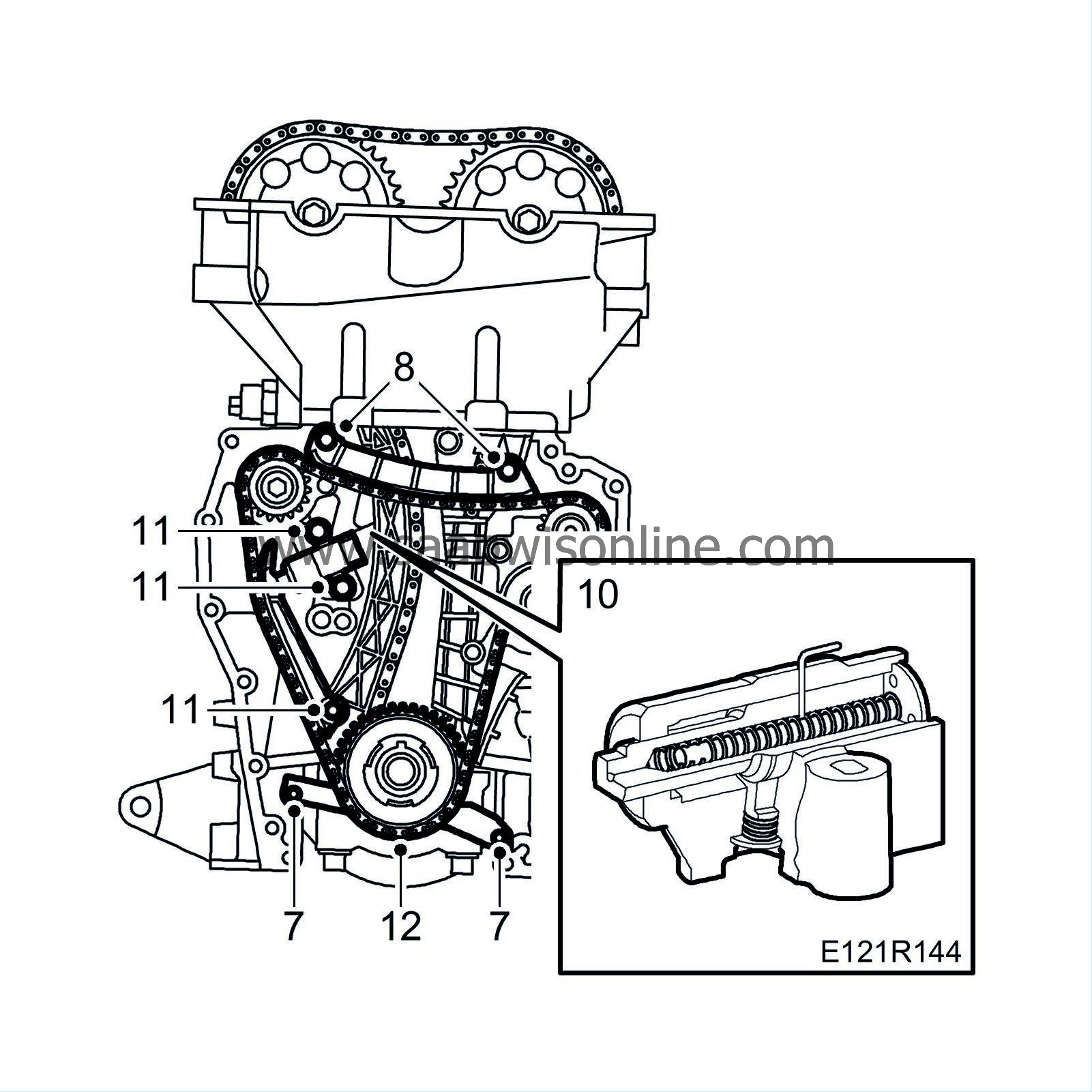
Remove the upper guide and the chain tensioner for the balancer shaft chain.
|
|
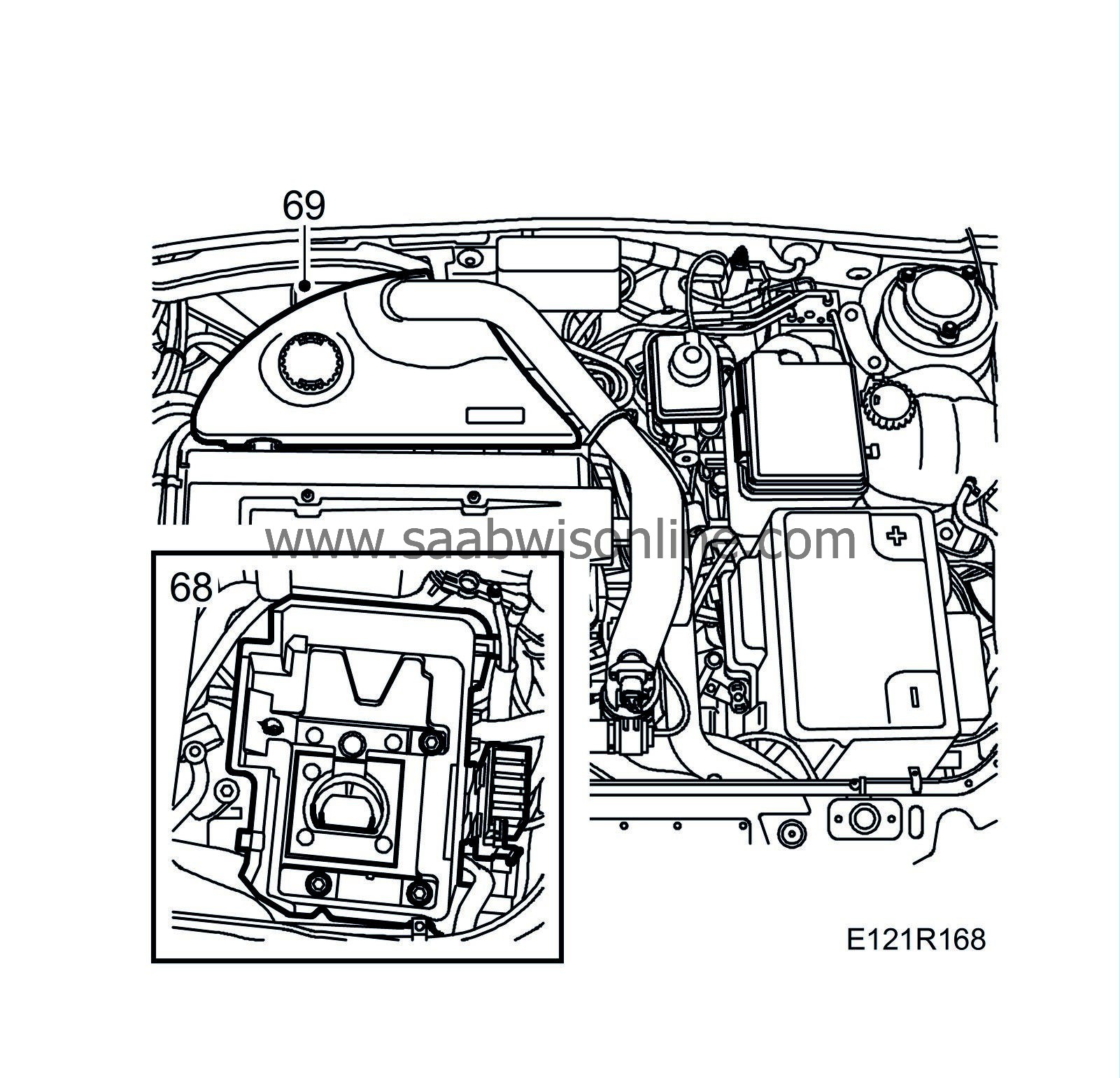
68.
|
Remove the pivoted guide from the balancer shaft chain.
|
|
69.
|
Remove the idler pulley for the balancer shaft chain and the chain.
|
|
70.
|
Remove the fixed guide for the balancer shaft chain and timing chain.
|
Note
|
|
The balancer shafts will move inwards in the engine when the balancer shaft pinion bolts are removed.
|
|
|
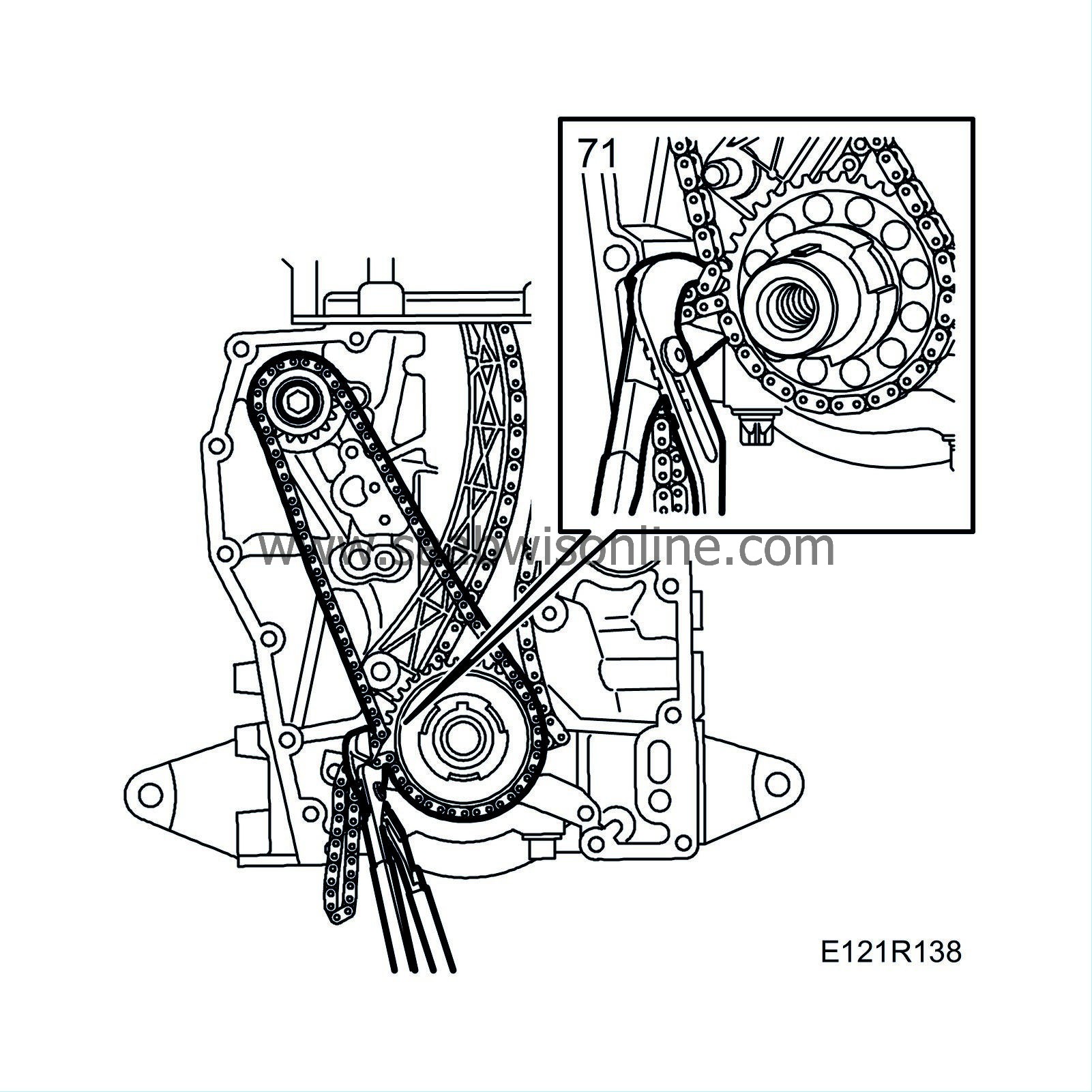
71.
|
Remove the balancer shaft pinions. Use the old balancer shaft chain as a counterhold when removing by placing the chain around the crankshaft sprocket and balancer shaft pinion. Hold together with pliers.
|
|
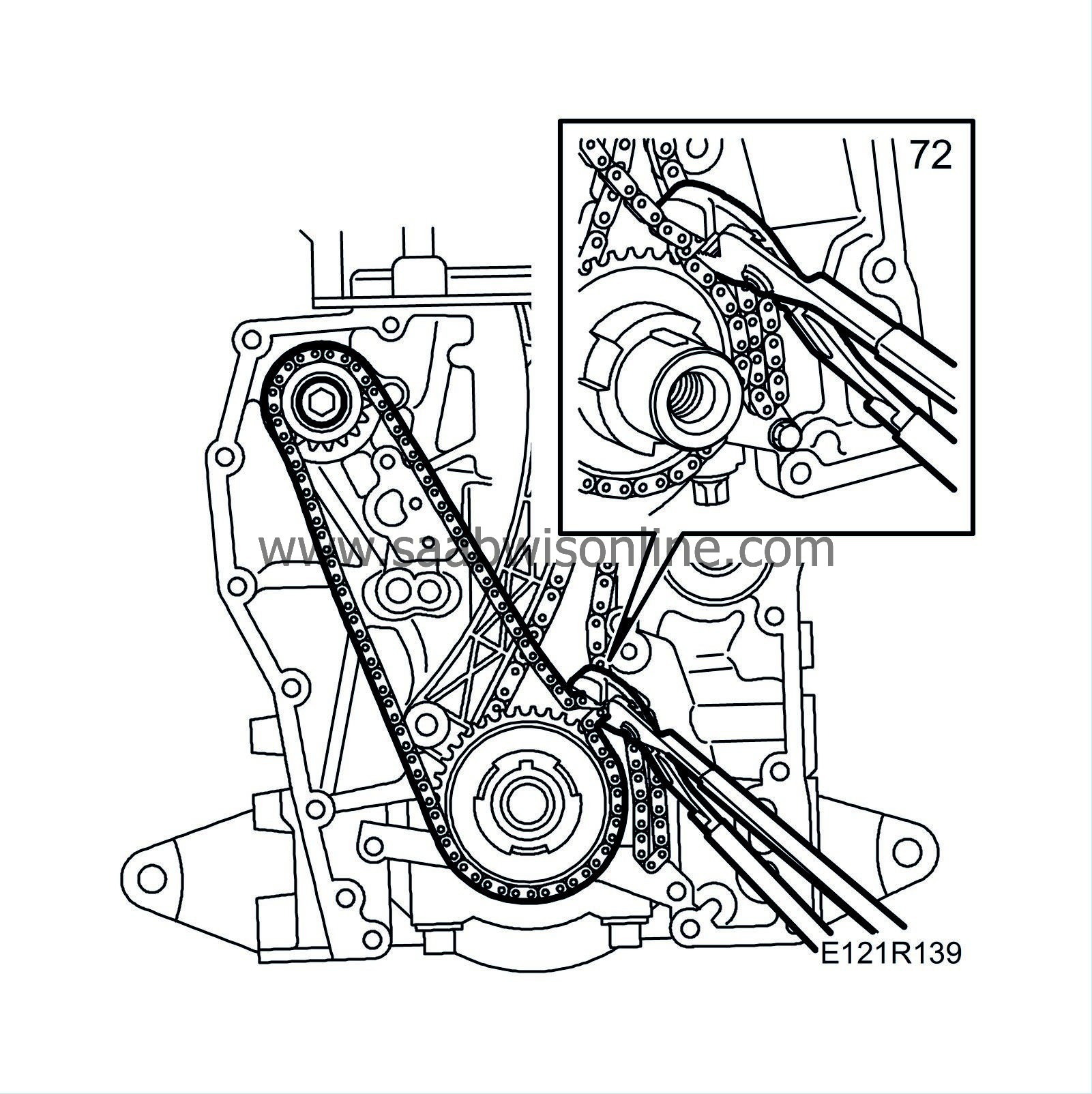
72.
|
Fit the new pinions with the chain as a counterhold.
Tightening torque: 25 Nm (18 lbf ft)
|
Important
|
|
The pinion with the smaller thrust ring marked INL must be fitted on the inlet side and the pinion with the larger thrust ring marked EXH must be fitted on the exhaust side.
|
|
|
|
|
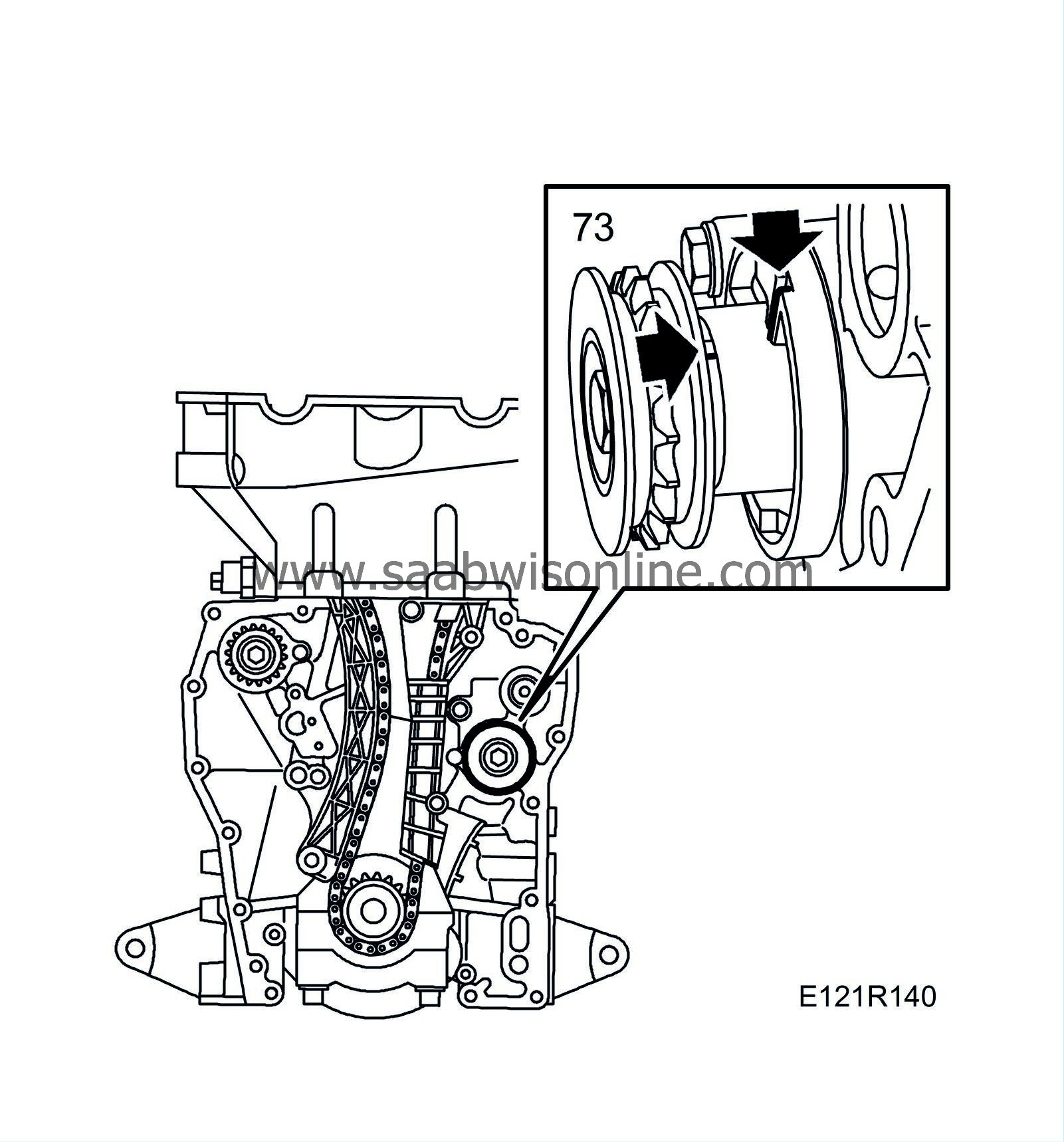
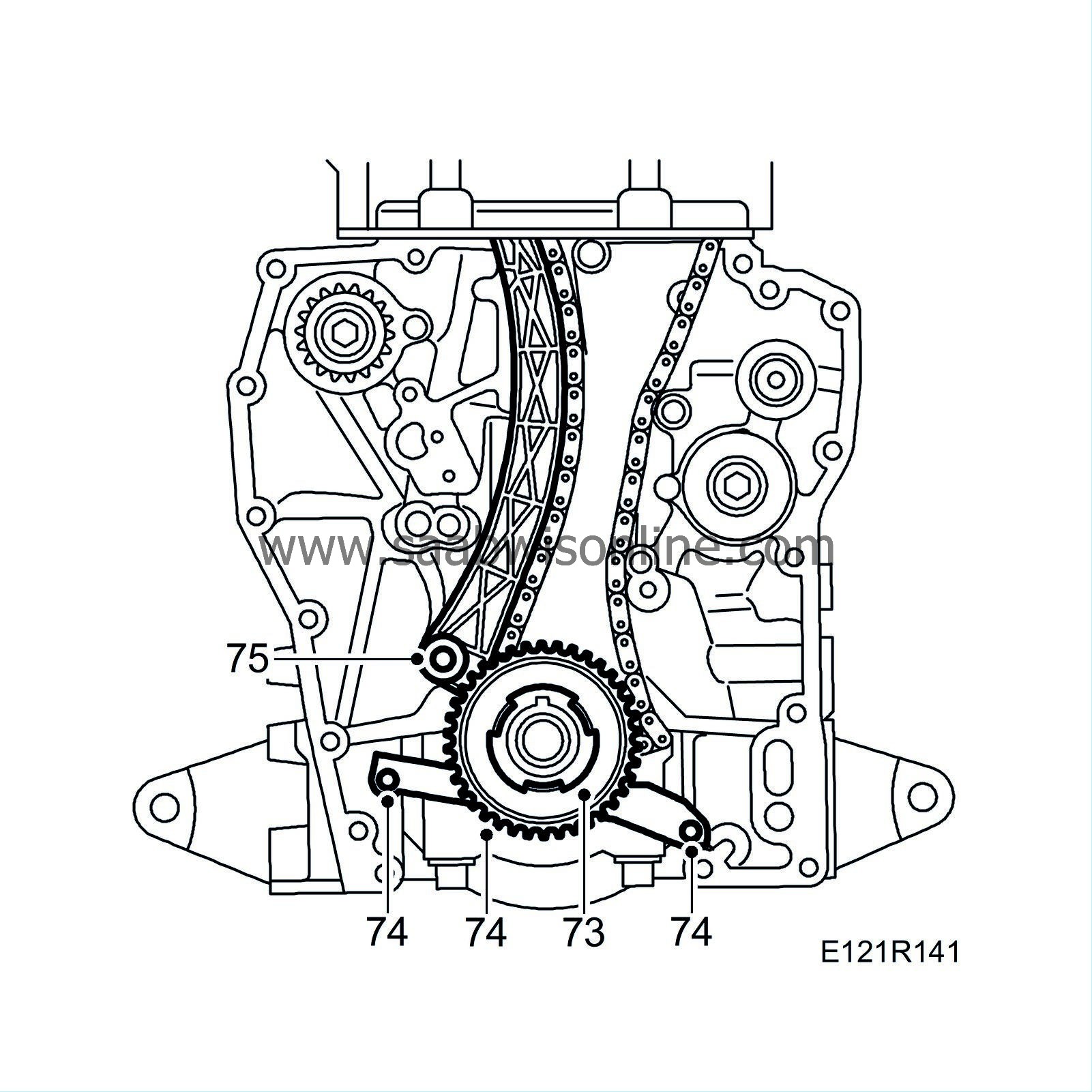
73.
|
Remove the oil pump driver and sprocket from the crankshaft.
|
|
74.
|
Remove the timing chain guard and remove the chain complete with sprocket.
|
|
75.
|
Remove the timing chain moving chain guide. Prise slightly to remove the guide.
|
|
76.
|
Clean the sealing surfaces of the oil sump and the timing cover, and wash the oil sump and the timing cover. Remove the baffle plate and suction strainer before washing.
|
|
77.
|
Replace the O-ring of the oil sump strainer.
|
|
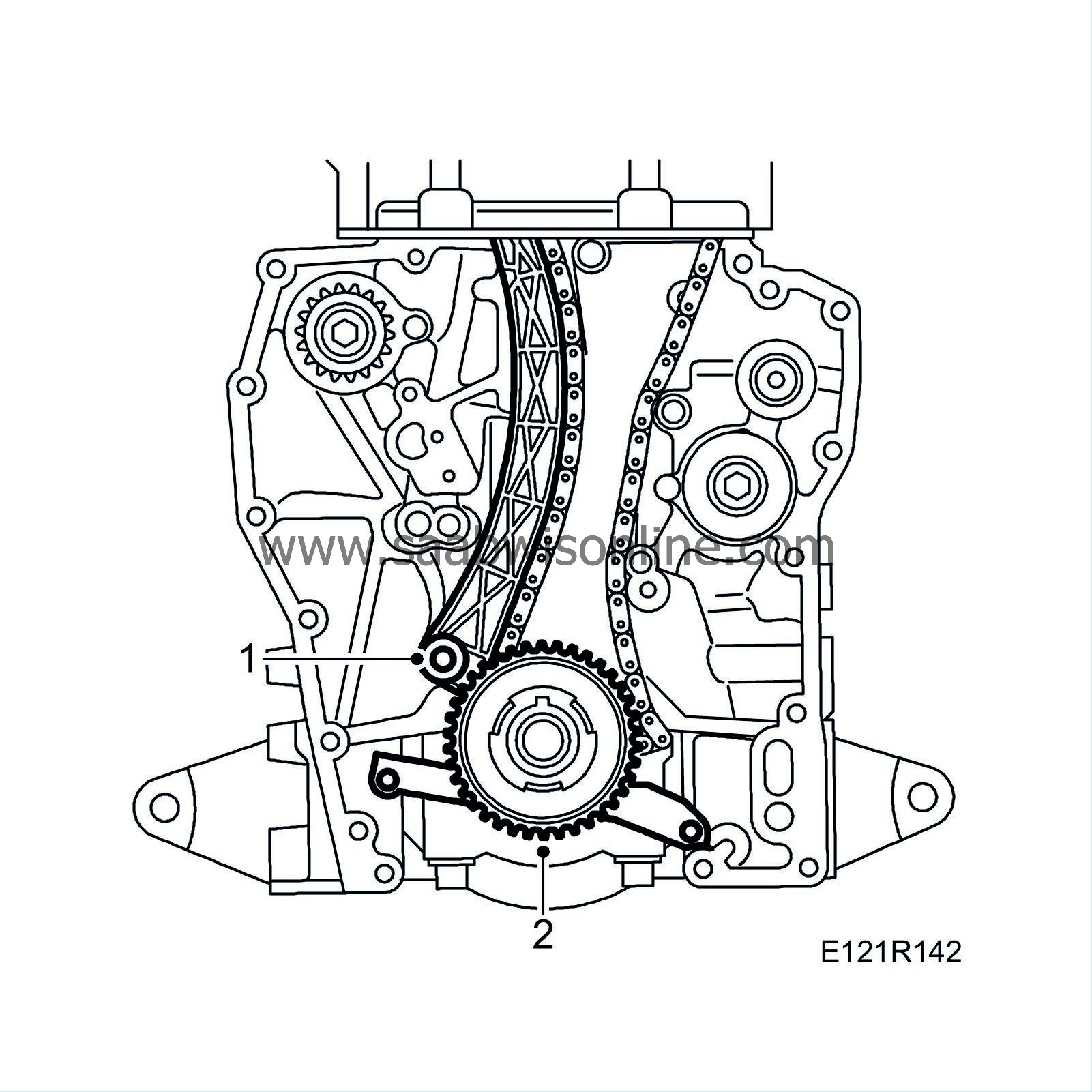
1.
|
Fit the timing chain moving chain guide. Prise slightly to fit the guide.
|
|
2.
|
Fit the timing chain pinion on the crankshaft.
|
|
3.
|
Fit the timing chain and camshaft sprockets according to the markings on the chain and wheel.
Tightening torque: 63 Nm (46 lbf ft)
|
|
4.
|
Fit the fixed guide for the balancer shaft chain and timing chain.
Tightening torque: 10 Nm (7 lbf ft)
|
|
5.
|
Fit the chain tensioner.
Tightening torque: 63 Nm (46 lbf ft)
|
|
6.
|
Fit the pin, spring and plug to the chain tensioner.
Tightening torque: 22 Nm (16 lbf ft)
|
|
7.
|
Fit the timing chain safety guard.
|
|
8.
|
Fit the balancer shaft chain upper guide.
Tightening torque: 10 Nm (7 lbf ft)
|
|
9.
|
Check that the chain tensioner plunger is correctly positioned. If the plunger can be depressed fully it must be turned 180°.
|
|
10.
|
Turn the plunger on the balancer shaft chain tensioner 90°, press it in and turn it back 90°. Lock the tensioner in position by inserting a paperclip or similar into the hole on the top of the tensioner.
|
|
11.
|
Fit the chain tensioner and the moving chain guide.
Tightening torque: 10 Nm (7 lbf ft)
|
Warning
|
|
Ii is very important for the function that the correct tightening torque is used when fitting.
|
|
|
|
|
|
|
|
12.
|
Fit the balancer shaft chain pinion on the crankshaft.
|
|
13.
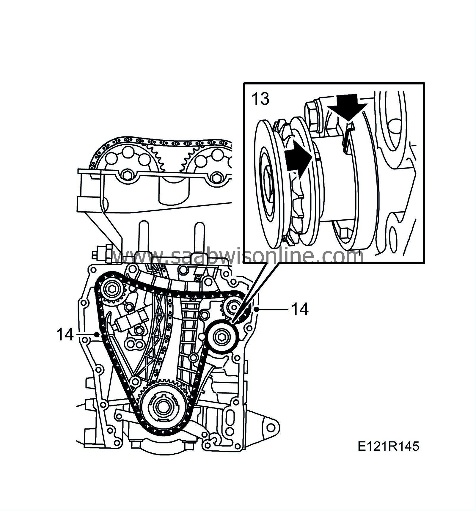
|
Align the mark on each balancer shaft with the mark on the top of its respective bearing housing.
|
|
14.
|
Fit the chain to the sprocket and fit this along with the idler sprocket.
Tightening torque: 25 Nm (18 lbf ft)
|
|
15.
|
Check the setting of the balancer shafts and release the chain tensioner. Counterhold with the moving guide, remove the wire clip from the chain tensioner and slowly ease out the guide.
|
|
16.
|
Check that there is a small amount of play by pushing in the tensioner.
|
|
17.
|
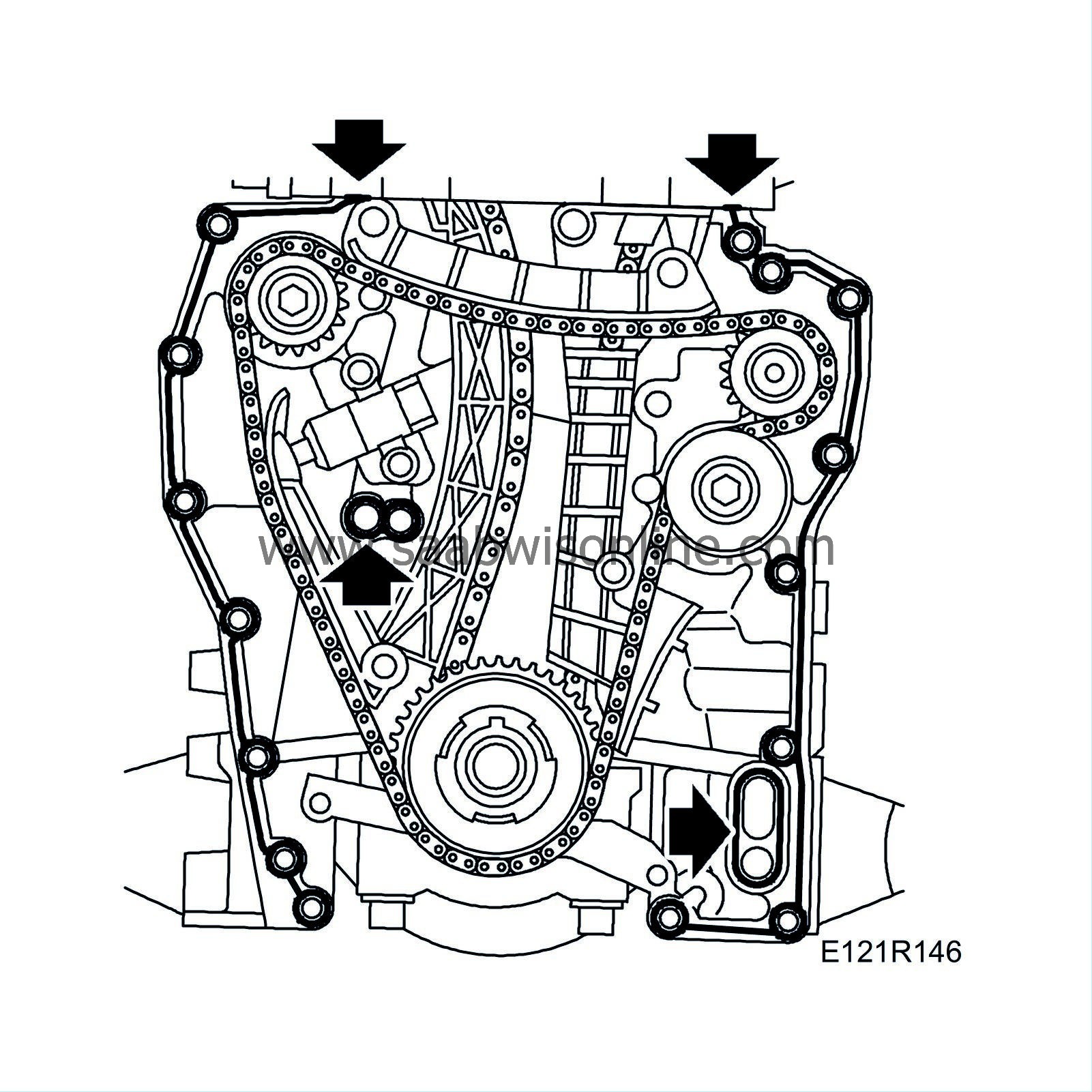
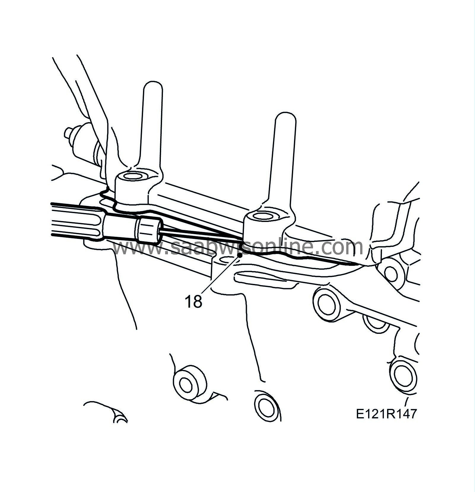
Apply
90 297 970 Flange sealant
in an approx. 1 mm thick line in the centre of the sealing surfaces according to the illustration. Apply a small dab of silicone flange sealant in the joins between the cylinder head and cylinder block.
|
|
18.
|
Fit the timing cover by carefully twisting it into place. Move the engine to the left and raise and lower to fit the timing cover and the bolts.
|
Note
|
|
Make sure that the cover does not catch on the cylinder head gasket. Guide the gasket away with a screwdriver.
|
Tightening torque 22 Nm (16 lbf ft) (up to and including engine no. 7006011)
Tightening torque 19 Nm (14 lbf ft) (from and including engine no. 7006012)
|
|
19.
|
Fit the oil pump driver.
|
|
20.
|
Make sure that the marking on the oil pump gear ring is facing outward and pump impeller with flange inward. Use a new O-ring, grease with Vaseline.
|
|
21.
|
Oil and fit the pump gears, fit the pump cover in correct position using the locating arrows.
|
|
23.
|
Fit the crankshaft pulley.
Tightening torque 175 Nm (129 lbf ft)
|
|
24.
|
Fit the bolt of the intermediate shaft bearing bracket.
|
|
25.
|
Fit the AC compressor bracket bolt.
|
|
26.
|
Fit the bolts for the generator bracket and the generator.
Tightening torque, generator 47 Nm (35 lbf ft)
Tightening torque, generator bracket 24 Nm (18 lbf ft)
|
|
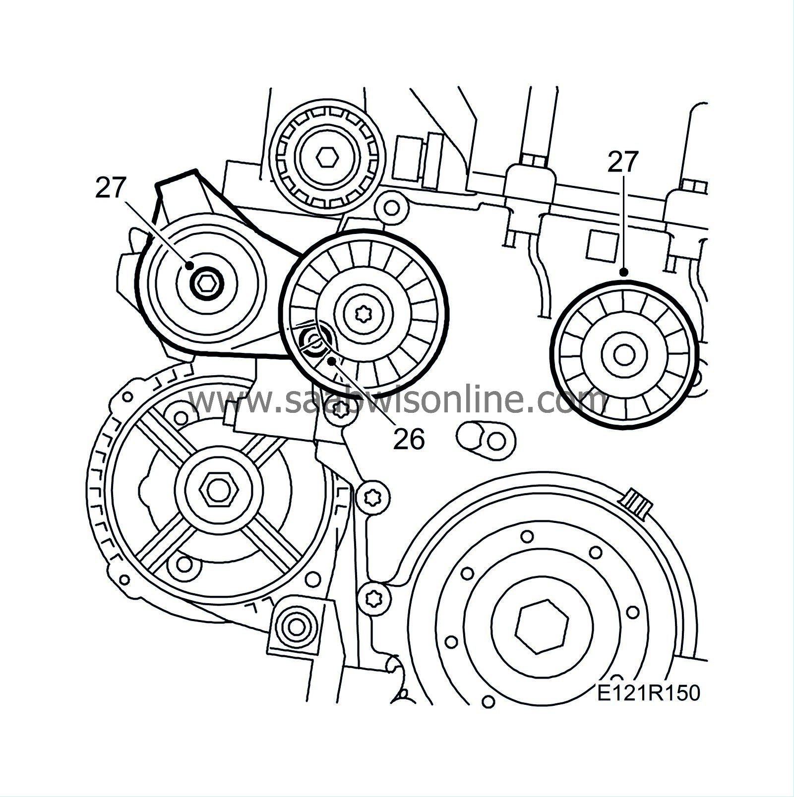
27.
|
Fit the belt tensioner and the idler pulley.
Tightening torque, belt tensioner 59 Nm (44 lbf ft)
Tightening torque, idler pulley 47 Nm (35 lbf ft)
|
|
28.
|
Man:
Fit the gearbox mounting.
Tightening torque, man. 47 Nm (35 lbf ft)
|
|
29.
|
Fit the left-hand engine pad. Centre the engine pad to the bolt holes. Remove the wedge.
Tightening torque bolts 40 Nm +45° (35 lbf ft +45°)
Tightening torque, nut 84 Nm (62 lbf ft)
|
|
30.
|
Fit the main fuse box.
|
|
31.
|
Lower the engine on the wedges at the oil filter adapter and the drive shaft universal joint. Remove the lifting eye.
|
|
32.
|
Fit the connection sleeve to the cylinder block. Apply
White high-pressure grease paste
to the seals. Polish the seat in the cylinder block with a fine emery cloth and fit two new O-rings.
|
|
33.
|
Fit the coolant pump.
Tightening torque: 22 Nm (16 lbf ft)
|
|
34.
|
Fit the coolant pipe to the coolant pump and the turbocharger.
Tightening torque, banjo screw, turbocharger 25 Nm (18 lbf ft)
Tightening torque, banjo screw, coolant pump 20 Nm (15 lbf ft)
|
|
35.
|
Fit the two longitudinal coolant pipes to the coolant pump.
Tightening torque: 10 Nm (7 lbf ft)
|
|
36.
|
Fit the two longitudinal coolant pipes to the engine block.
|
|
37.
|
Fit the hose clips and hoses to the coolant pump inlet.
|
|
38.
|
Fit the intake manifold to the turbocharger with a new O-ring.
|
|
39.
|
Fit the bracket for the power steering pump and the power steering pump.
Tightening torque: 24 Nm (18 lbf ft)
|
|
40.
|
Fit the camshaft cover according to the fitting sequence in the illustration.
|
|
42.
|
Fit the engine lifting eye.
|
|
43.
|
Fit the fan cowling.
|
|
44.
|
Fit the multigroove belt in accordance with the indicated rotation direction.
|
|
45.
|
Fit the mass air flow sensor with hose and connector.
|
|
46.
|
Raise the engine and fit the right-hand engine mounting.
Tightening torque: 47 Nm (35 lbf ft)
|
|
47.
|
Fit the engine mounting bracket. Do not fit the nut yet.
Tightening torque, bolts 47 Nm (36 lbf ft)
|
|
48.
|
Fit the crankcase ventilation pipe.
|
|
49.
|
Fit the turbocharger solenoid valve and the connector.
|
|
50.
|
Fit the ignition discharge module without plugging in the connector.
|
|
51.
|
Raise the car and remove the flywheel locking attachment.
|
|
52.
|
Apply an approximately 2 mm thick bead of flange sealant, part no. 90 543 772 to the oil sump sealing surface.
|
|
53.
|
Check that the pipe to the oil adapter is firmly attached and that it is directed straight into the oil sump. Replace O-rings if necessary.
|
|
54.
|
Lift up and position the oil sump. Thread all the bolts.
|
|
55.
|
Tighten the oil sump bolts.
Tightening torque: 22 Nm (16 lbf ft)
|
|
56.
|
Fit the crankcase ventilation hose.
|
|
57.
|
Fit the gearbox cover plate.
|
|
58.
|
Fit the oil filter and connect the oil pipes with new O-rings.

|
|
59.
|
Fit the front exhaust pipe.
Tightening torque: 22 Nm (16 lbf ft)
|
|
60.
|
Fit the torque arm.
Tightening torque, through bolt 90 Nm + 90° (66 lbf ft + 90°)
Tightening torque, bracket 70 Nm + 90° (52 lbf ft + 90°)
|
|
61.
|
Lower the car and fit the nuts to the right-hand and rear engine pads.
Tightening torque, rear 47 Nm (35 lbf ft)
Tightening torque, right 105 Nm (78 lbf ft)
|
|
62.
|
Tighten the upper nuts on the exhaust pipe flange and plug in the connector to the heated oxygen sensor. Secure the cable with cable ties.
Tightening torque: 22 Nm (16 lbf ft)

|
|
63.
|
Fit the turbocharger heat shield.
|
|
64.
|
Fit the by-pass valve with pipe.
|
|
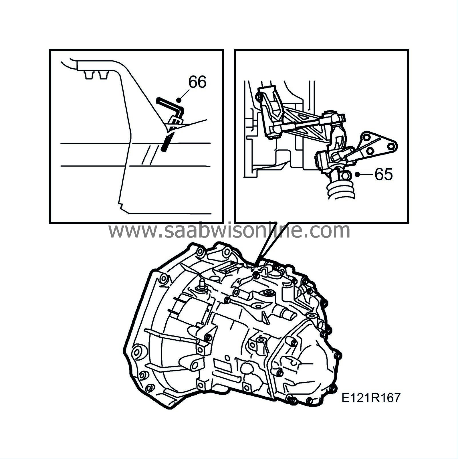
65.
|
Connect the gear linkage to the selector rod.
|
|
66.
|
Man:
Engage 4th gear and fit
87 92 632 Lock pin
in the gear-lever housing. Tighten the clamp on the gear linkage.
Tightening torque: 22 Nm (16 lbf ft)
|
|
67.
|
Remove the lock pins, check the gear positions and that the ignition key can be removed. Fit the plastic plug in the gearbox. Fit the gear lever gaiter.
|
|
68.
|
Fit the battery tray and the battery. Fit the battery cover. Connect the battery cables.
|
|
69.
|
Fit the upper engine cover.
|
|
70.
|
Raise the car and fit the spoiler shield.
|
|
71.
|
Fit the right-hand wing liner.

|
|
72.
|
Fit the belt circuit's cover.

|
|
74.
|
Pressure test the cooling system.
|
|
75.
|
Fill with
Coolant
and close the expansion tank cap.
|
|
76.
|
Fill with engine oil.
|
|
77.
|
Run the starter motor until the oil pressure lamp goes out without the ignition discharge module connector being plugged in. Plug in the connector afterwards.
|
Note
|
|
A diagnostic trouble code is generated after running the starter motor.
|
|
|
78.
|
Set the car clock and date.
|
|
80.
|
Connect the diagnostic tool and erase the diagnostic trouble codes.
|


