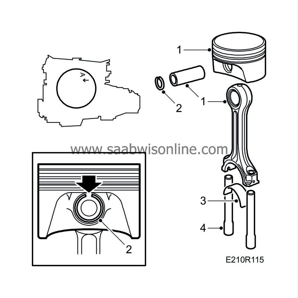
Pistons, connecting rod, cylinder bores
|
|
Pistons, connecting rod, cylinder bores
|
|
Important
|
|
Pistons of different makes must not be used in the same engine. The name of the manufacturer is cast inside the piston.
|
|
|
Spare pistons are stocked in both standard and oversize diameters. Where the latter are used, the cylinder bore must be honed or rebored to obtained the correct piston clearance.
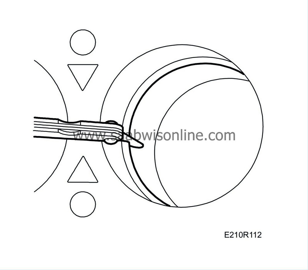
When matching pistons in the cylinder bores, use a 1/2" wide feeler gauge. The cylinder bore should be lightly oiled during measuring and the piston, without rings, should be placed in its corresponding bore. Hook a spring balance to the feeler gauge and insert the gauge between the piston and the bore at right angles to the gudgeon pin. When the pulling force is 8-12 N (1.8-2.7 lbf), the mean value of the clearance coincides with the thickness of the feeler gauge. The test should be performed at several different levels. For piston clearance information, see
Pistons
Example cylinder classification A piston type A.
When the piston clearances are measured in the engine by means of a 0.05 mm feeler gauge, no measurable force will be recorded on the spring balance when withdrawing the feeler gauge from the No. 2 and No. 3 cylinders. This means that the piston clearance in these cylinders is greater than 0.05 mm and the maximum bore in them is therefore judged to be 90.020 mm. Since the pistons may have bedded-in to a certain extent, giving a further +0.003 mm, it may be assumed that the bore is 90.023 mm. Assuming a standard class B piston, the theoretical piston clearance will be 0.034-0.052 mm and this lies within the clearance limits which for class A piston/class A cylinder is 0.031-0.069 mm, and for class B piston/class B cylinder is also 0.031-0.069 mm. In No. 1 and No. 4 cylinders, the pistons cannot be fitted into the cylinder bores with a 0.05 mm or 0.04 mm feeler gauge inserted. With a 0.03 mm feeler gauge inserted the force necessary to withdraw it will be 20 N (4.6 lbf) and with a 0.02 mm feeler gauge it will be 6 N (1.4 lbf). We can therefore assume a piston clearance of 0.024 mm in the No. 1 and No. 4 cylinders and the pistons in these cylinders will therefore not need to be replaced.
Fitting in a new or rebored cylinder
|
1.
|
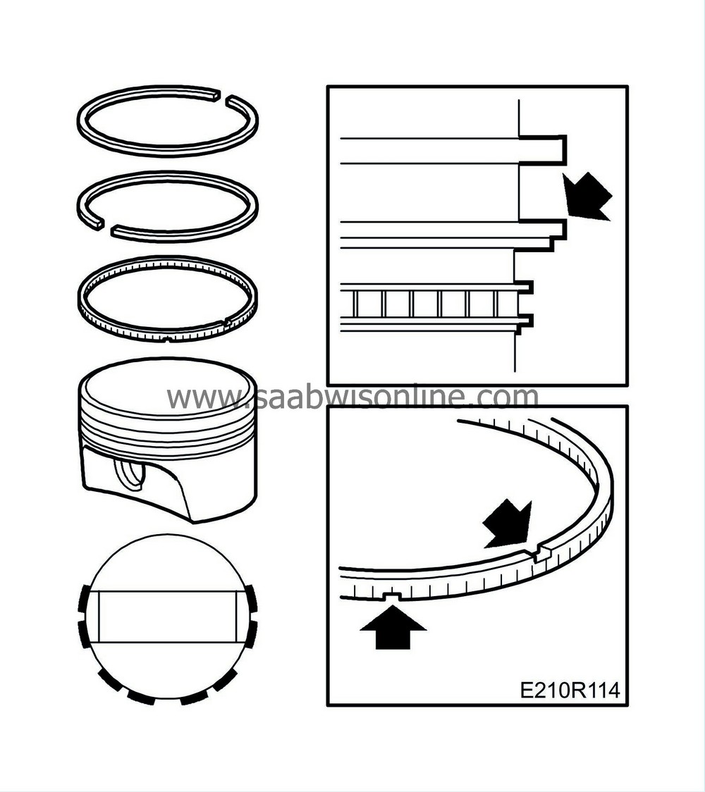
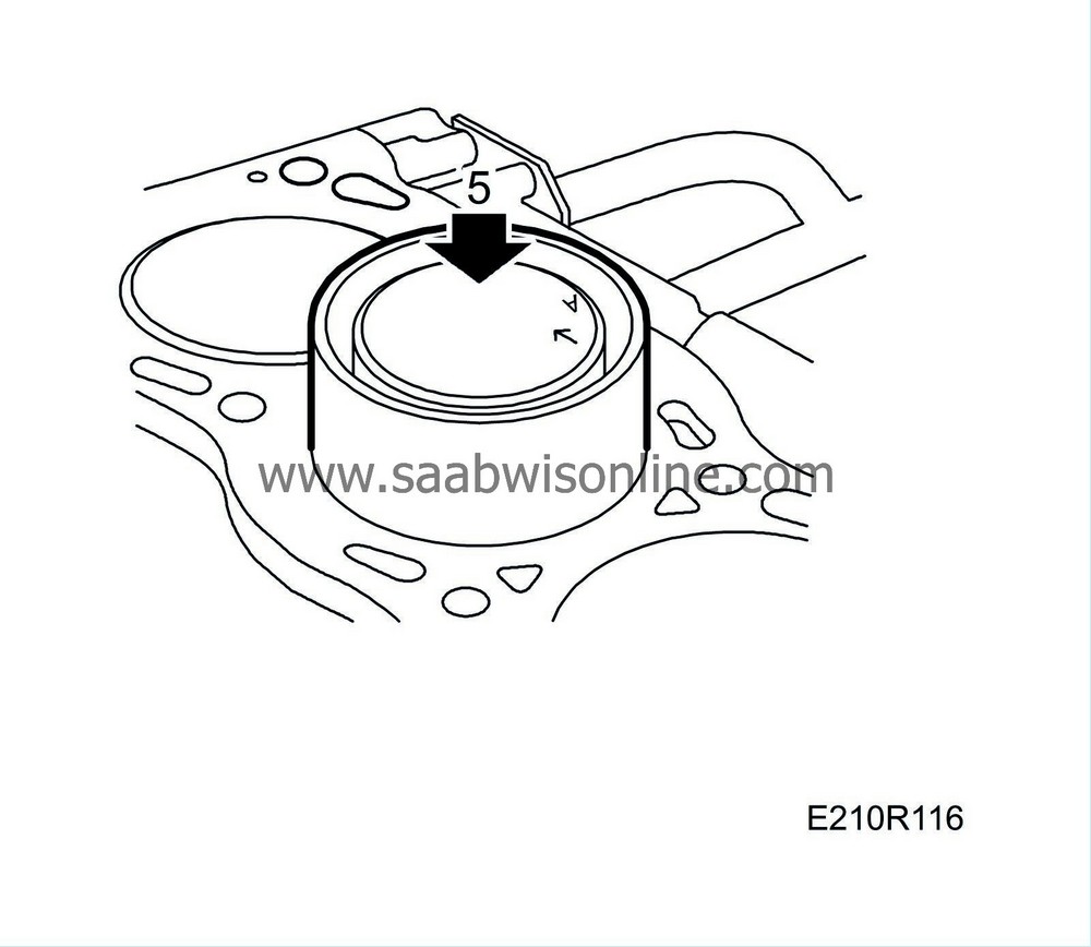
Push the piston rings down into the cylinder one by one, using a piston to position them correctly.
|
|
2.
|
Measure the ring gap with a feeler gauge, see illustration. If necessary, the gap can be increased with a special file. For measurement information, see
Pistons
.
|
Fitting in a worn cylinder
Piston rings for a worn cylinder should be matched in the same way as for a new or rebored cylinder, but they must be tried at the lower limit of piston travel because the bore is narrowest at this point.
In connection with piston ring replacement, the cylinder bore should be honed before the rings are fitted.
|
a.
|
Use a piston ring clamp to fit the rings on the piston.
|
|
b.
|
The lower compression ring should be fitted with the side marked “top" facing up.
|
|
c.
|
Check the fit of the piston rings in their grooves by rolling them round the grooves. Also measure the clearance at several points.
|
|
d.
|
Oil the piston and rings before assembly. Turn the compression rings so that their gaps are roughly 180 to each other and position each of them above one of the gudgeon pin holes.
|
|
e.
|
Make sure that the gaps in the top and bottom rings of the three-part scraper ring are staggered round the piston and not in line with each other.
|
|
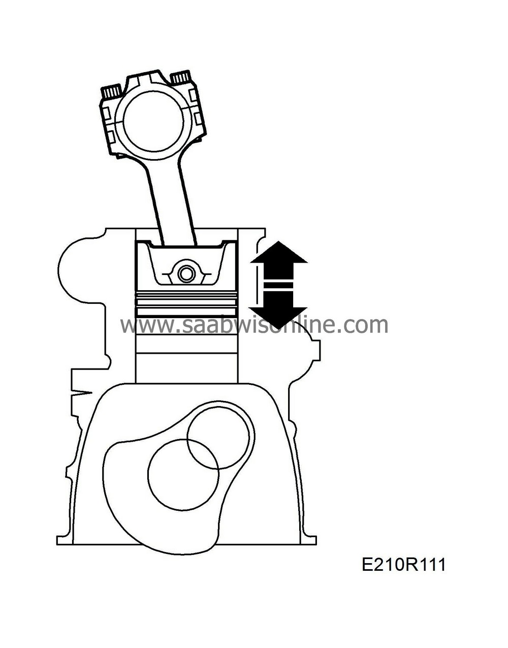
Fitting pistons (in situ)
|
|
1.
|
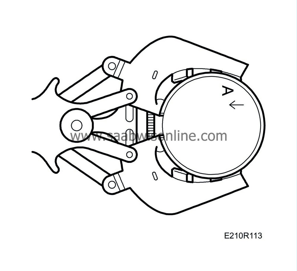
Assemble piston and connecting rod by driving in the gudgeon pin, using a plastic mallet and drift. Make sure that the mark on the piston crown faces the timing cover and that the numbers on the connecting rods face the exhaust side.
|
Important
|
|
If one connecting rod is to be changed to a newer type (part no. 91 97 617), all the connecting rods must be changed or the difference in weight will become too great.
|
|
|
|
|
2.
|
Fit the gudgeon pin lock ring.
 Warning
|
|
It is extremely important to fit the lock ring with its opening upwards.
|
|
|
|
|
|
|
|
3.
|
Place the bearing halves in place in the connecting rods.
|
|
4.
|
Fit
Protective collars
75 19 531 over the connecting rod studs and oil the piston rings, bearings and cylinder.
|
|
5.
|
Fit the piston using piston fitting tool 78 62 287.
|
Important
|
|
Pistons of different makes must not be used in the same engine. The name of the manufacturer is cast inside the piston.
|
|
|
|
|
6.
|
Fit the big-end bearing caps with bearing halves (connecting rod numbers facing in the same direction).
Tightening torque, with nut 20 Nm +70° (15 lbf ft +70°)
Tightening torque, with bolt 25 Nm +100° (18 lbf ft +100°)
|
|
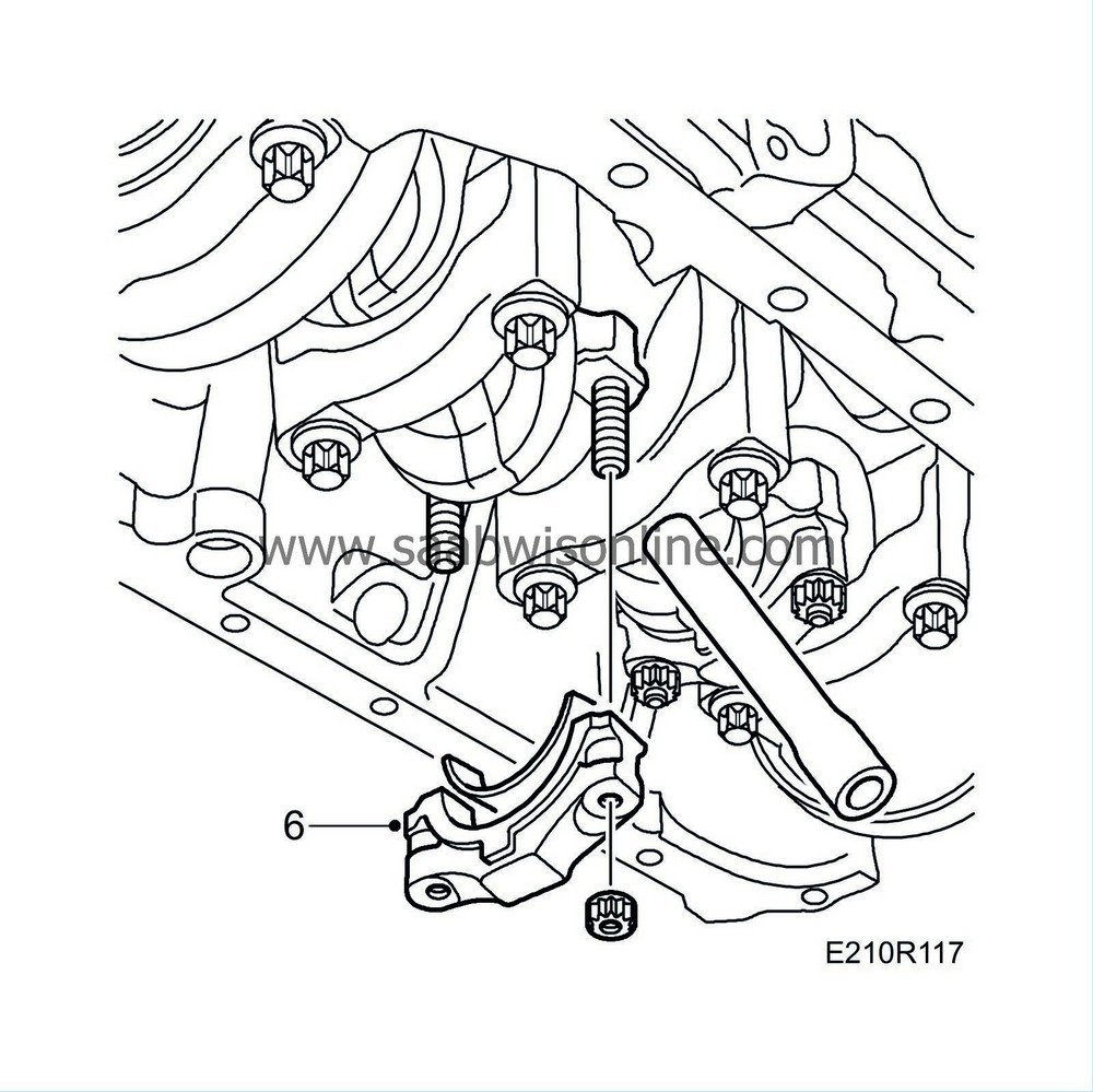
8.
|
Place a
Wedge
83 95 238 between the subframe and oil sump and remove the lifting beam.
|


