|
No.
|
Name
Location
|
Illustration
|
|
Components
|
|
2
|
Alternator,
on the rear of the engine (RH)
|

|
10
|
Light switch,
on the instrument panel between the steering wheel and the driver's door
|

|
22a
|
Fuse box, dashboard
on end of dashboard next to driver's door
|

|
42
|
Level switch, brake fluid,
on the brake fluid reservoir
|

|
43
|
Contact, handbrake,
under the floor console by the handbrake
|

|
44
|
Pressure switch, engine oil
under the intake manifold
|

|
46
|
Fuel level sensor,
in the fuel tank
|

|
342a
|
Fuse box, engine compartment,
behind the battery
|

|
445
|
Data link connector, 16-pin, CARB
under dashboard by steering column
|

|
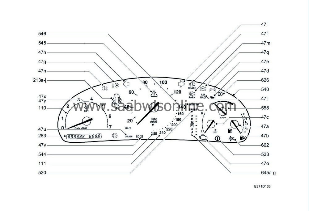
540
|
Main instrument unit,
in front of driver in dashboard
|

|
541
|
SID module,
on the rear of the main instrument unit
|

|
663FL
|
LH headlamp
to the left of the radiator
|

|
663FR
|
RH headlamp
to the right of the radiator
|

|
|
|
4-pin connector
|
|
H4-2
|
Under the rear seat
|

|
|
|
10-pin connector
|
|
H10-4
|
Under the rear seat
|

|
|
|
16-pin connector
|
|
H16-9
|
On the side of the tank
|

|
|
|
24-pin connector
|
|
H24-1
|
Grey connector in middle of bulkhead partition (engine compartment side)
|

|
H24-2
|
Black connector located centrally on the bulkhead partition (engine compartment side)
|

|
|
|
43-pin connector
|
|
H43-1
|
White connector in the connector console under the LH A-pillar
|

|
|
|
80-pin connector
|
|
H80-1
|
In the connector console under the left A-pillar
|

|
|
|
Crimp connectors
|
|
J42
|
LHD:
Approx. 145 mm from grounding point G40 branching point towards fuse box
RHD:
Approx. 50 mm from branching point of grounding point G42 towards relay box
|

|
J58
|
LHD:
Approx. 280 mm from branching of MIU/SID towards DICE control module
RHD:
Approx. 260 mm from rear of DICE control module connector towards the engine bay
|

|
J60
|
LHD:
Approx. 40 mm from branching of DICE control module towards fuse box
RHD:
Approx. 240 mm from rear of DICE control module connector towards the engine bay
|

|
J63
|
LHD:
Approx. 160 mm from branching DICE control module towards the fuse box
RHD:
Approx. 110 mm from branching data link connector towards DICE control module
|
|
J174
|
LHD:
Approx. 140 mm from branching of H33-1 connector towards main fuse box
RHD:
--
|

|
J200
|
Approx. 380 mm from branching of brake unit towards engine bay main fuse box
|

|
|
|
Grounding points
|
|
G30
|
In the engine compartment on the side plate in front of the LH wheel housing
|

|
G40
|
In the cabin on the LH side of the knee member
|

|
G41S
|
LH ground screw in the middle of the knee member (in the cabin)
|

|
G42
|
In the cabin on the RH side of the knee member
|

|

