PRE-RELEASE
Camshafts (in situ)
| Camshafts (in situ) |
|
||||||||||||||||||||||
| To remove |
|
|||||||
| Important | ||
|
Always use wing covers when working in the engine bay. |
||
| 1. |
Remove
Timing belt (in situ)
.
|
|
| 2. |
Remove
EGR solenoid valve (606), Z19.
|
|
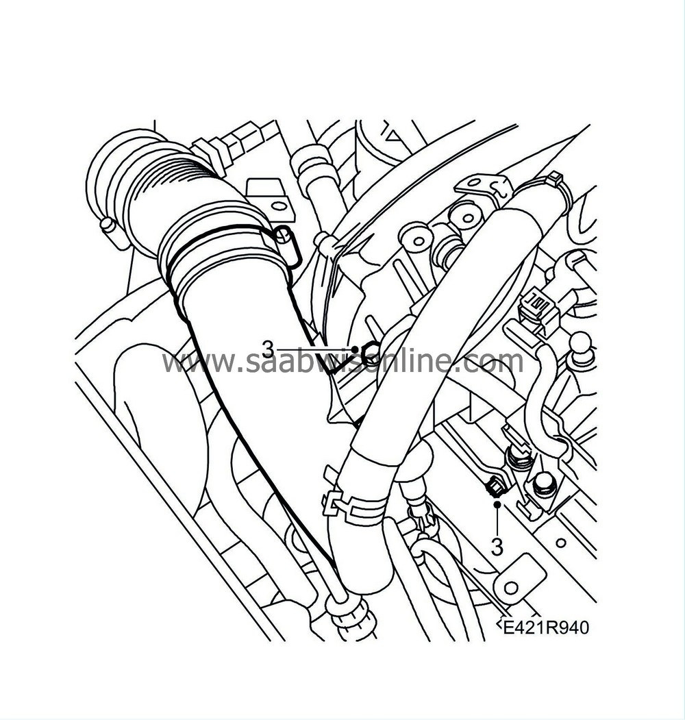
| 3. |
Undo the turbocharger delivery pipe's upper mounting slightly.
|
|
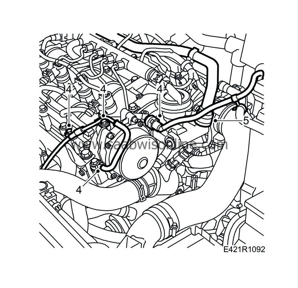
| 4. |
Remove the brake servo's hose and the turbocharger control valve's vacuum hose and remove the vacuum pipe.
|
|
| 5. |
Detach the crankcase ventilation hose from the cylinder head.
|
|
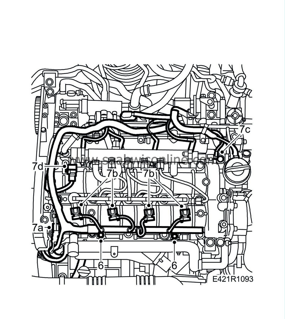
| 6. |
Remove the cable duct retaining bolts.
|
|
| 7. |
Unplug the following connectors:
|
|
| 7.a. |
Camshaft position sensor (555)
|
| 7.b. |
Injectors (206)
|
| 7.c. |
Fuel pressure sensor (653).
|
| 7.d. |
Fuel pressure solenoid valve (652a).
|
| 8. |
Move the engine wiring harness aside.
|
|
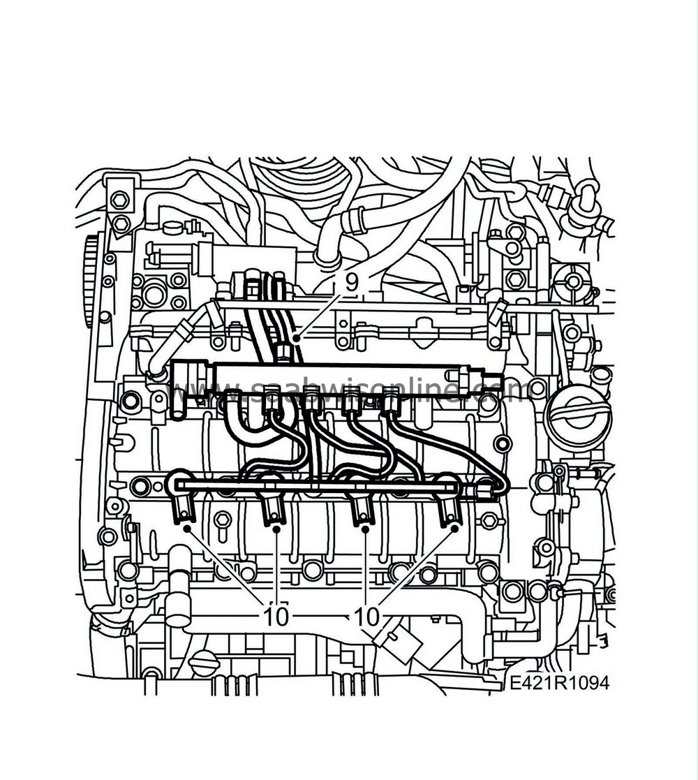
| 10. |
Remove the
Injector (206)
.
|
|
| 11. |
Detach the fuel rail and move it aside.
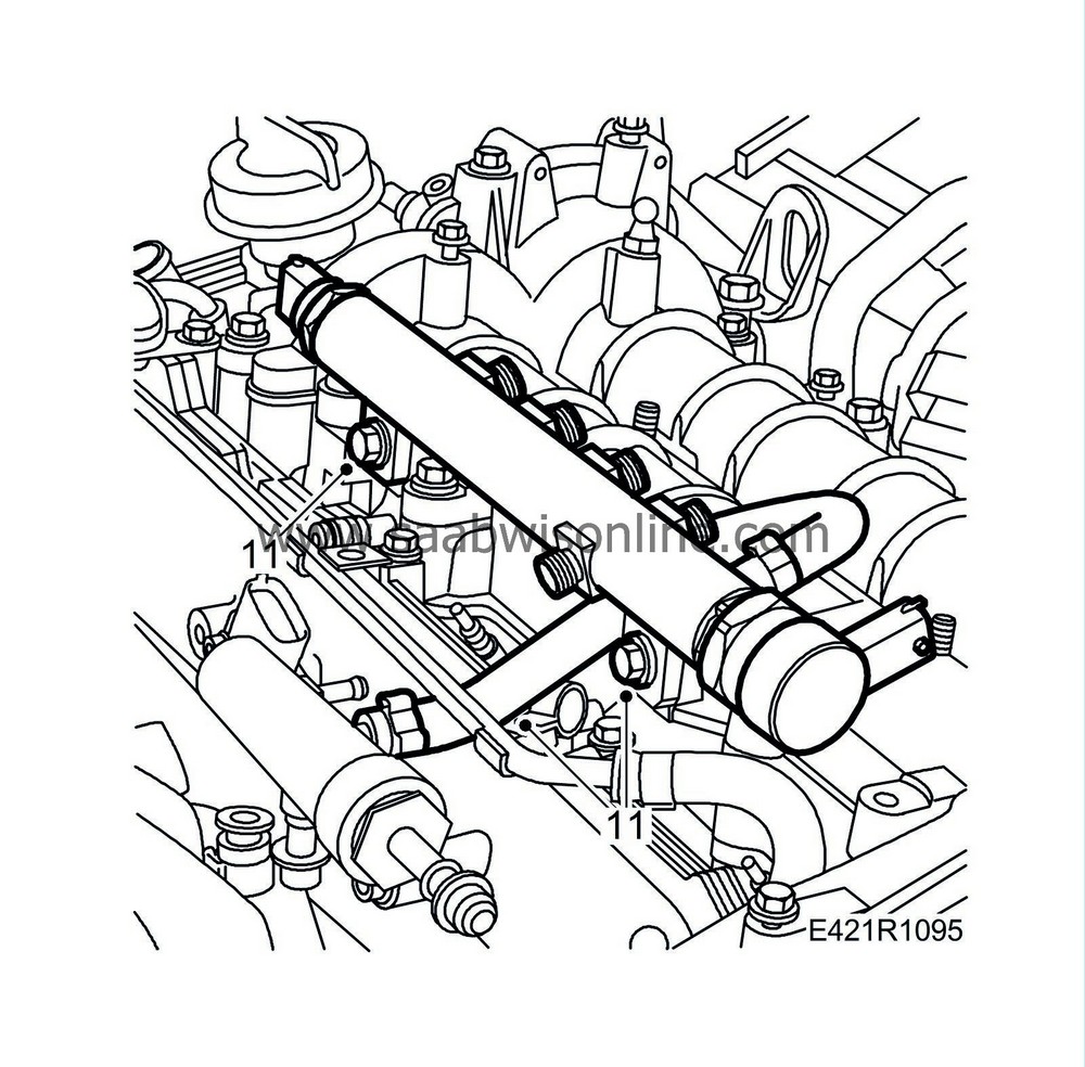
|
|
| 12. |
Detach the charge air hose from the pipe and throttle body.
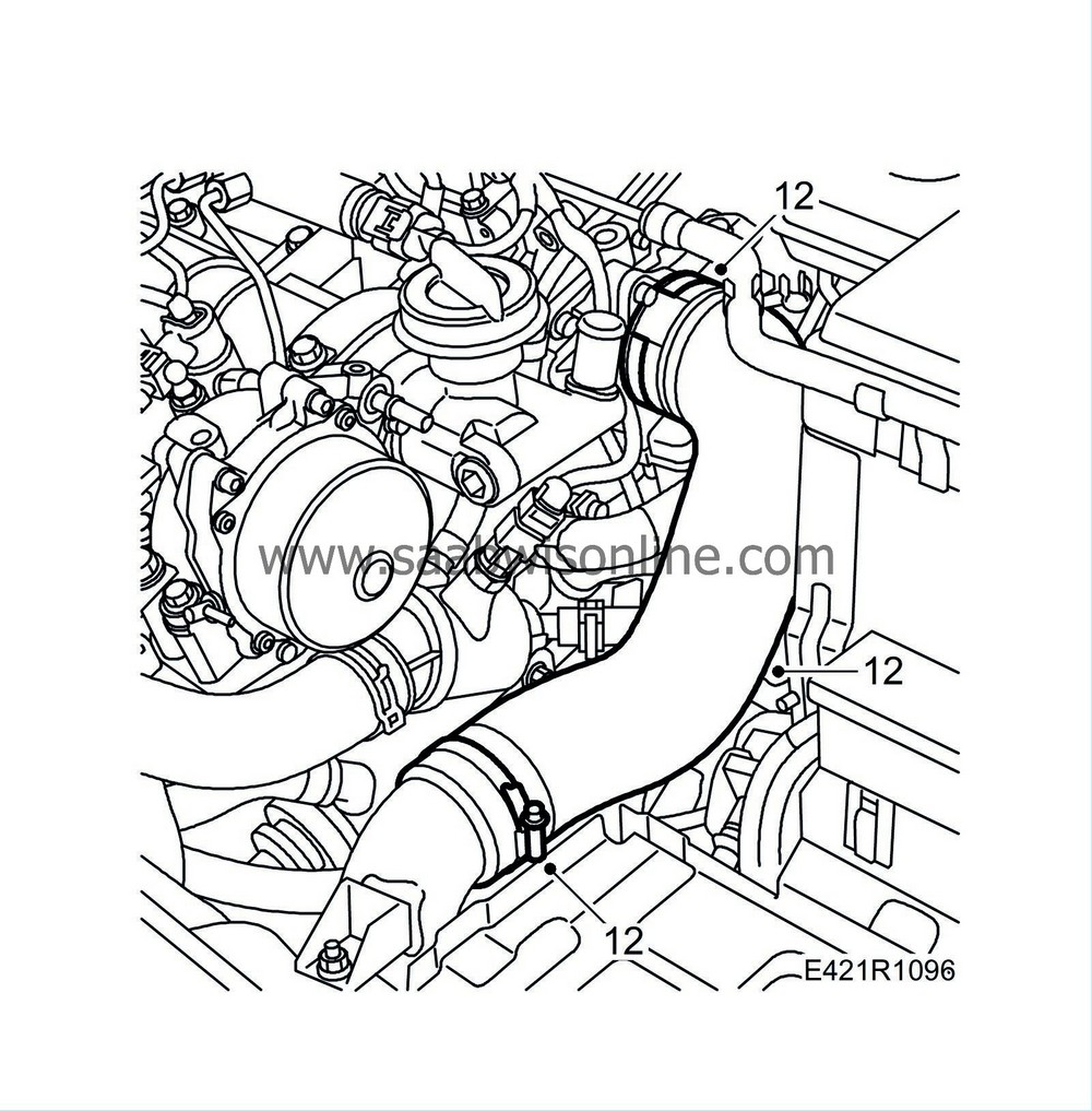
|
|
| 13. |
Remove the vacuum pump.
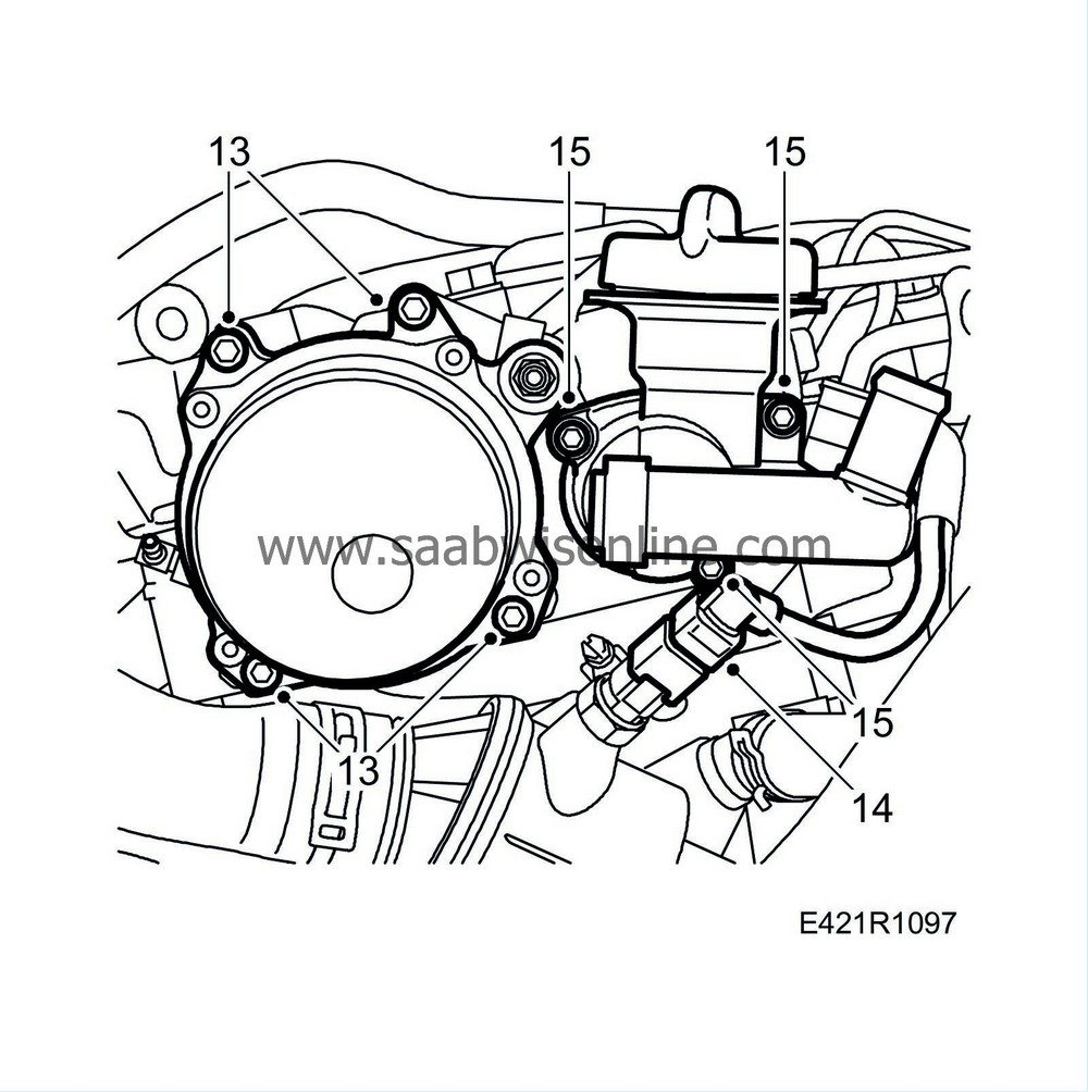
|
|
| 14. |
Unplug the temperature sensor connector.
|
|
| 15. |
remove the oil filer port.
|
|
| 16. |
Check that
32 025 008 Camshaft fixing tool
has locked the exhaust camshaft in place.
|
|||||||
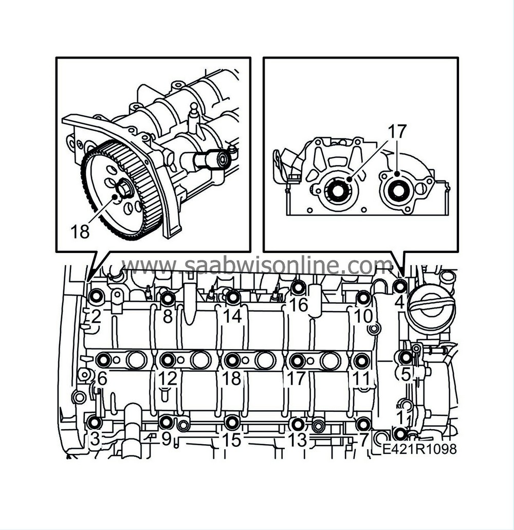
| 17. |
Slacken the bolts of the camshaft gear wheels.
|
|
| 18. |
Slacken the bolt of the camshaft drive wheels.
|
|
| 19. |
Loosen and remove the camshaft shaft housing and the guide sleeves. Remove in alternating order as illustrated.
|
|
| 20. |
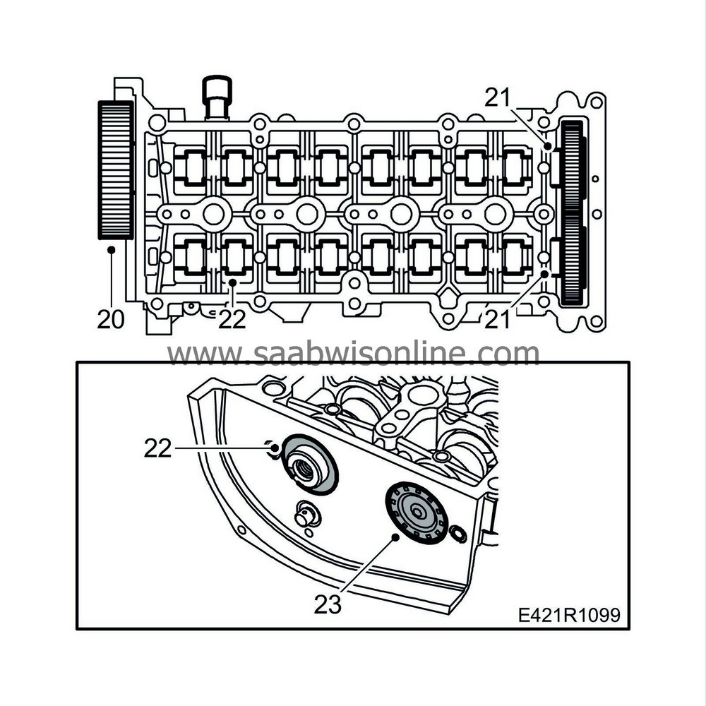
Remove the camshaft drive wheels.
|
|
| 21. |
Remove the camshaft gear wheels.
|
|
| 22. |
Remove the seal ring of the exhaust camshaft using a suitable tool. Be careful so as not to damage the sealing surface. Remove the exhaust camshaft.
|
|
| 23. |
Press out the intake camshaft and seal plug.
|
|
| To fit |
| 1. |
Lubricate the bearing surfaces with engine oil. Fit the camshafts.
|
|
| 2. |
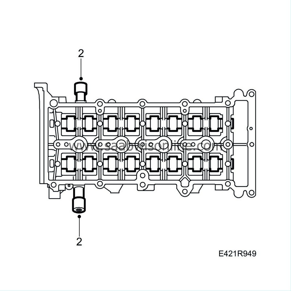
Lock both camshafts with
32 025 008 Camshaft fixing tool
. Check that the tool is correctly fitted. The reference drifts must audibly engage.
|
|
| 3. |
Fit the camshafts' gear wheels. The gear wheel with drive lugs is to be fitted on the exhaust camshaft.
Tightening torque: 120 Nm (88 lbf ft) 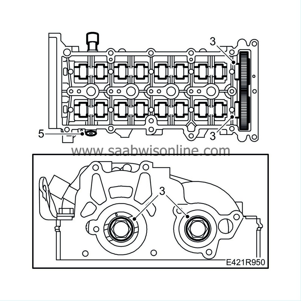
|
|
| 4. |
Remove the fixing tool on the inlet side.
|
|
| 5. |
Fit the seal plug using a new O-ring.
|
|
| 6. |
Clean the sealing surfaces of the vacuum pump and oil filler port.
|
|
| 7. |
Clean away any gasket residue from the sealing surfaces of the cylinder head and camshaft housing.
|
|
| 8. |
Fit the vacuum pump using a new seal.
Tightening torque: 9 Nm (7 lbf ft) 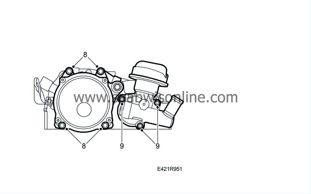
|
|
| 9. |
Fit the oil filler port using a new seal.
Tightening torque: 9 Nm (7 lbf ft) |
|
| 10. |
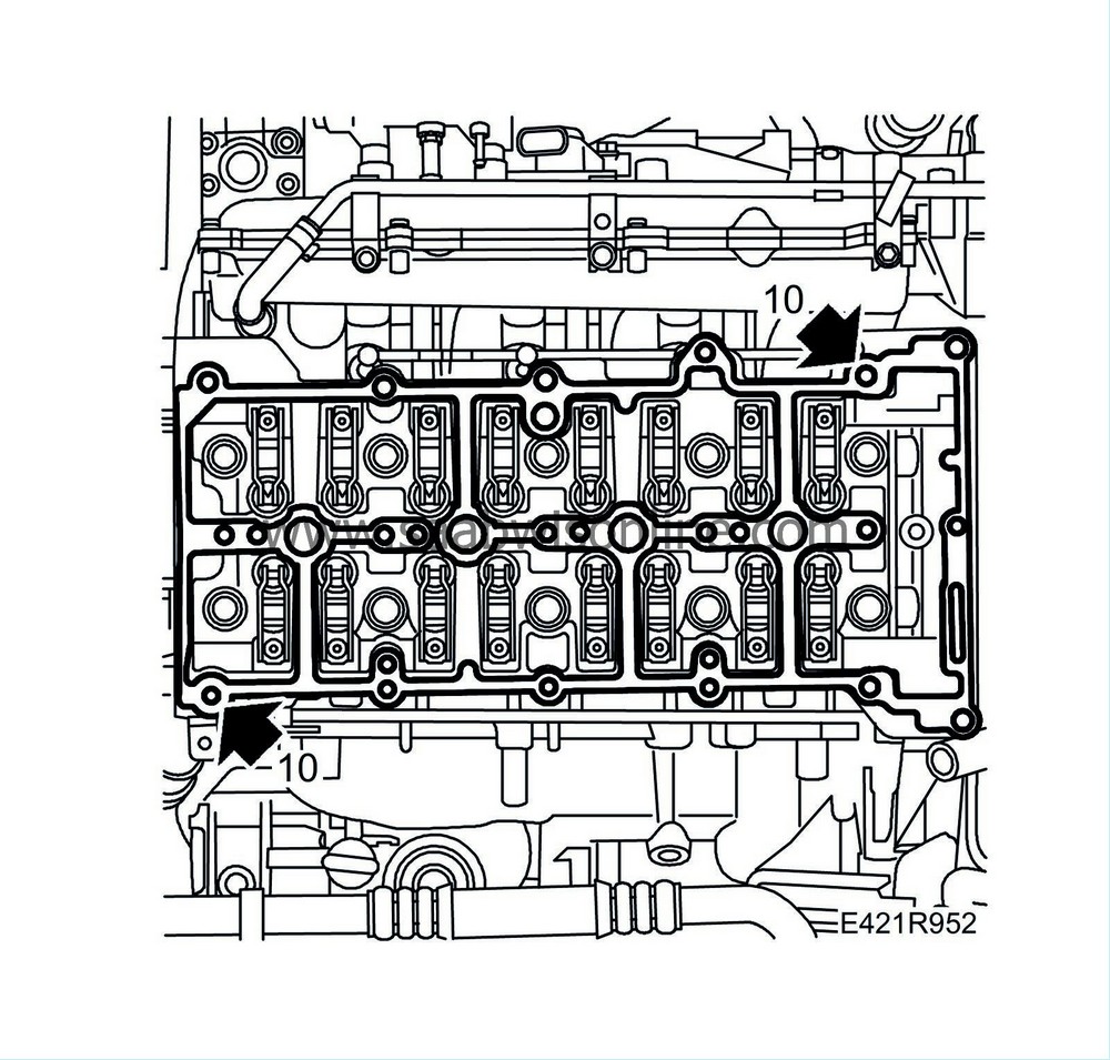
Fit the guide sleeves and position a new gasket on the cylinder head.
|
||||||||||
| 11. |
Fit the camshaft housing, tightening the bolts alternatingly. Check that the guide sleeves are properly positioned in the camshaft housing.
Tightening torque: 25 Nm (15 lbf ft) 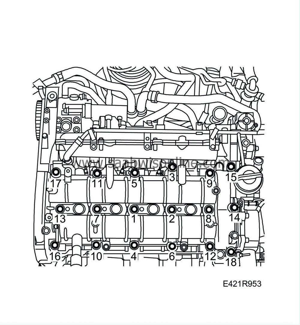
|
|
| 12. |
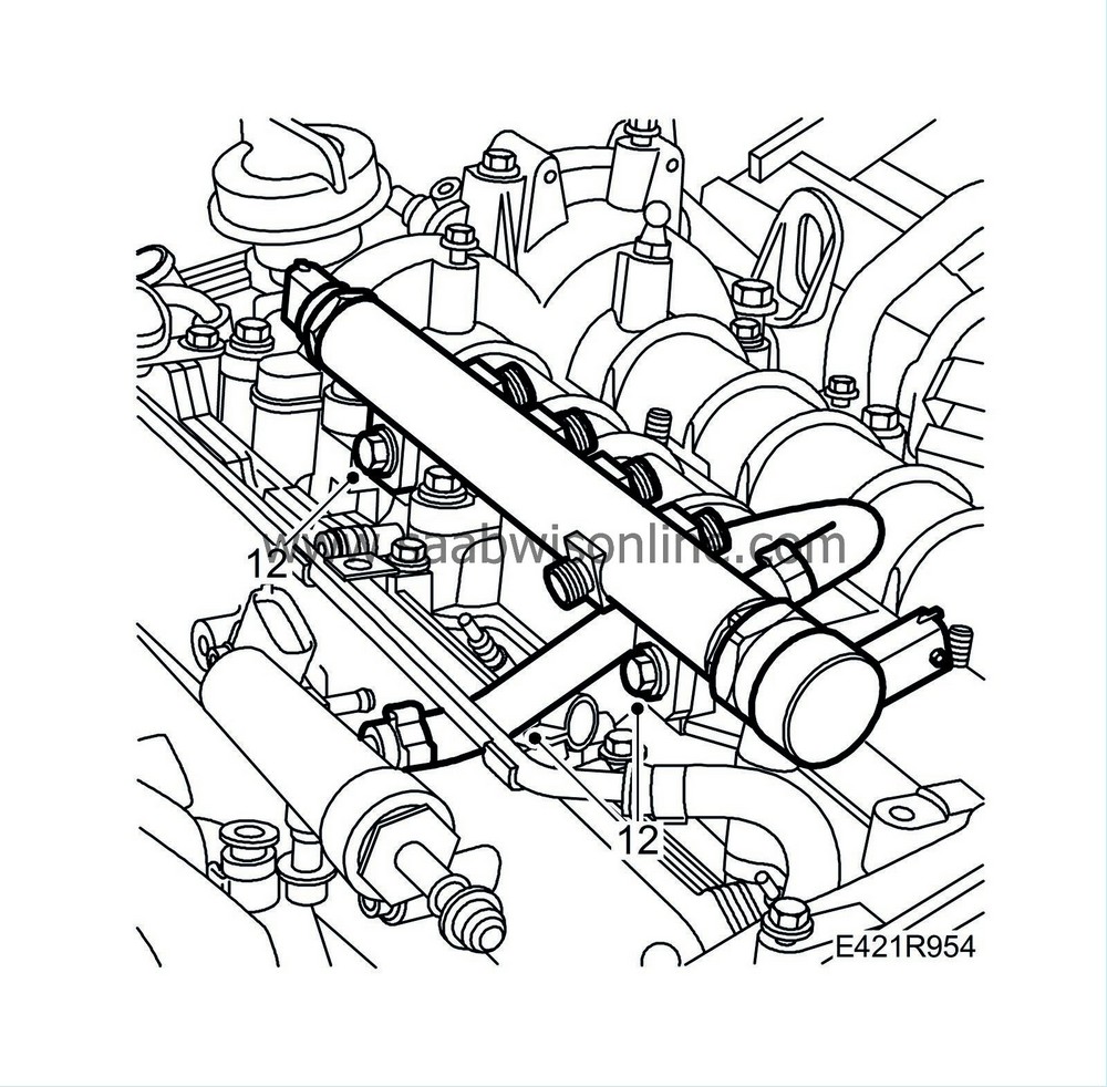
Fit the fuel rail.
|
|||||||||||||
| 13. |
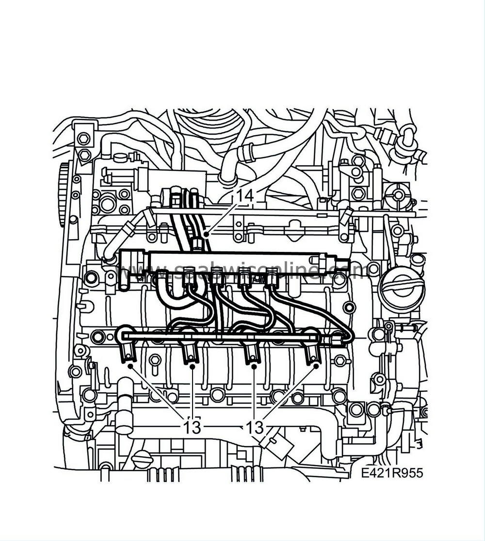
Fit the
Injector (206)
.
|
|
| 14. |
Attach the fuel delivery pipe between the pump and fuel rail.
Tightening torque: 25 Nm (18 lbf ft) |
|
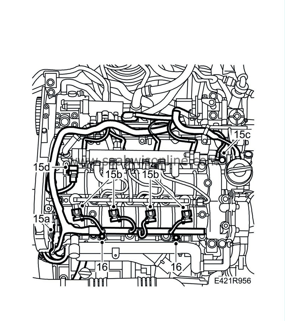
| 15. |
Plug in the following connectors:
|
|
| 15.a. |
Camshaft position sensor (555)
|
| 15.b. |
Injectors (206)
|
| 15.c. |
Fuel pressure sensor (653).
|
| 15.d. |
Fuel pressure solenoid valve (652a).
|
| 16. |
Fit the cable duct retaining bolts and secure the wiring harness.
|
|
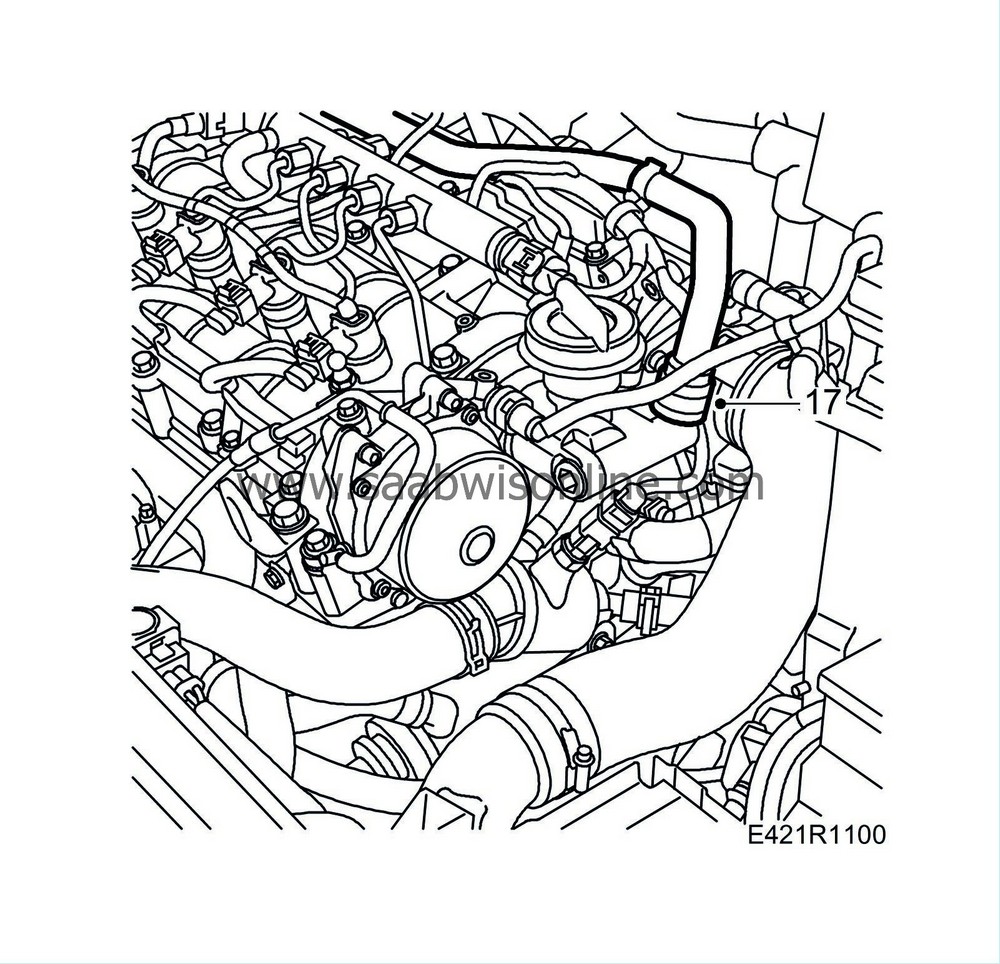
| 17. |
Attach the crankcase ventilation hoses to the cylinder head.
|
|
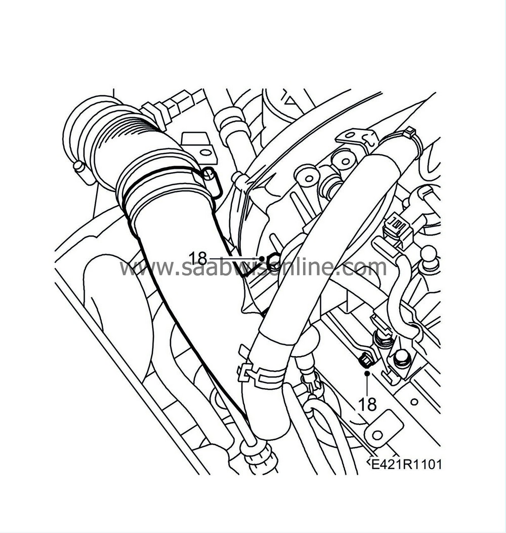
| 18. |
Tighten the mounting of the turbocharger intake manifold.
|
|
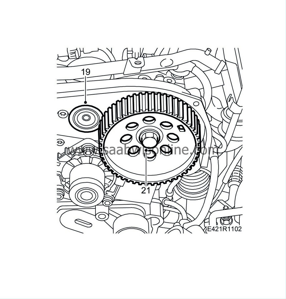
| 19. |
Fit the intake camshaft seal plug.
|
|
| 20. |
Lubricate the seal ring with
90 167 353 Silicone paste
. Fit the camshaft seal ring using
32 025 050 Fitting tool, camshaft seal
.
|
|
| 21. |
Fit the camshaft drive wheels using a new bolt. Tighten the bolt just enough that it lies against the drive wheel but so that the drive wheel can still be turned in relation to the exhaust camshaft. The exhaust camshaft should be locked with
32 025 008 Camshaft fixing tool
.
|
|
| 22. |
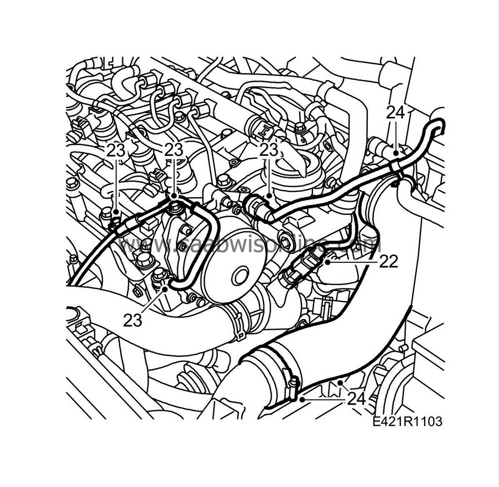
Plug in the temperature sensor connector.
|
|
| 23. |
Fit the brake servo's hose and the turbocharger control valve's vacuum hose to the vacuum pump. Fit the vacuum pipe.
|
|
| 24. |
Attach the charge air hose.
Tightening torque 4 Nm (3 lbf ft) |
|
| 25. |
Fit
EGR solenoid valve (606), Z19.
|
|
| 26. |
Fit
Timing belt (in situ)
. Before removing
32 025 008 Camshaft fixing tool
, tighten the bolt of the camshaft drive wheels once the timing belt has been adjusted. The drive wheel must not turn when the bolt is tightened.
Tightening torque: 120 Nm (89 lbf ft) |
|

 Warning
