PRE-RELEASE
Auxiliary heater, Z19, Man, LHD
| Auxiliary heater, Z19, Man, LHD |
| To remove |
| 1. |
Raise the car.
|
|
| 2. |
Remove the front left wheel.
|
|
| 3. |
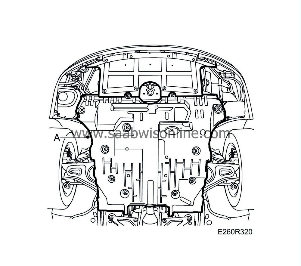
Remove the lower engine cover (A).
|
|
| 4. |
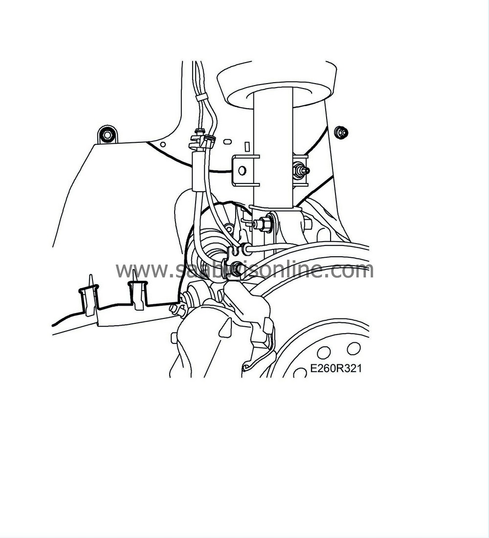
Remove the left side cover.
|
|
| 5. |
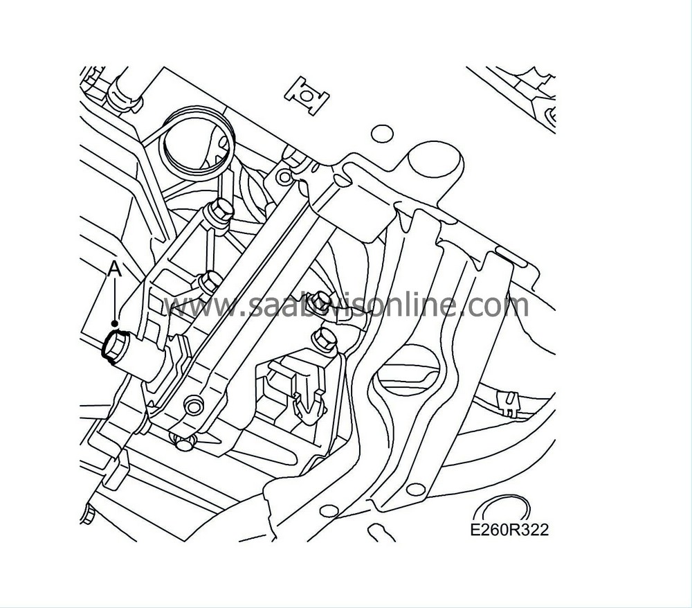
Remove the bolt from the torque rod (A).
|
|
| 6. |
Undo the clamp (A) on the auxiliary heater's exhaust pipe and the clamp on the intake pipe. Remove the intake pipe.

|
|
| 7. |
Remove the support plate (B) and detach the auxiliary heater's exhaust pipe (C).
|
|
| 8. |
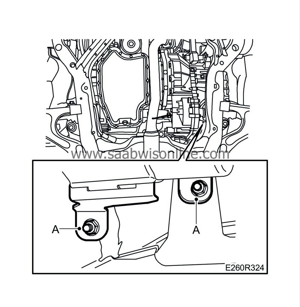
Remove the two lower nuts (A) on the auxiliary heater bracket.
|
|
| 9. |
Lower the car.
|
|
| 10. |
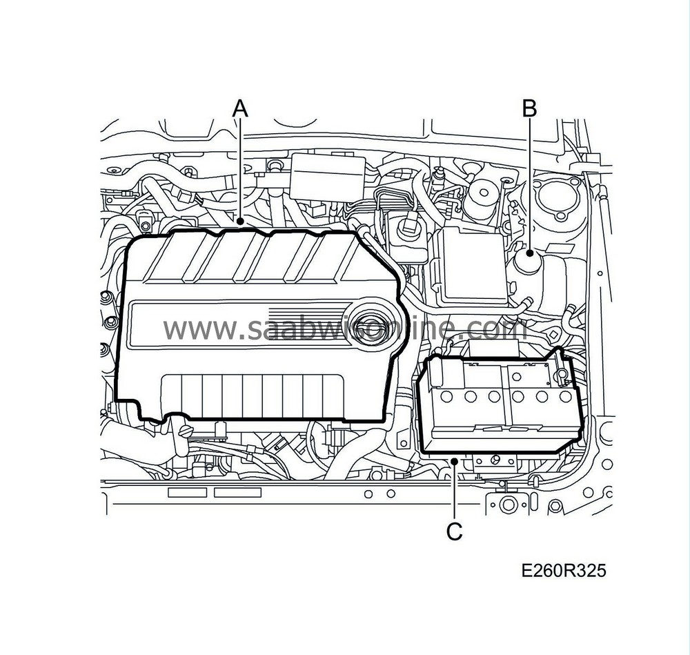
Remove the upper engine cover (A).
|
|||||||||
| 11. |
Carefully open the expansion tank cap (B) and release any excess pressure.
|
|
| 12. |
Remove the battery (C).
|
|
| 13. |
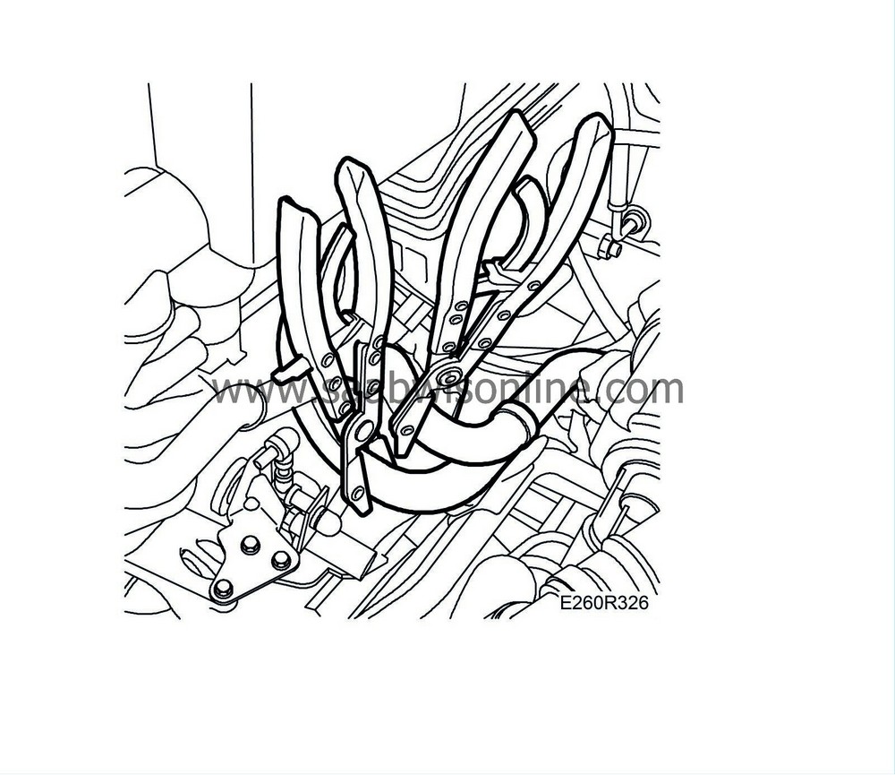
Clamp the coolant hoses between the engine and auxiliary heater with
30 07 739 Hose pinch-off pliers
.
|
|
| 14. |
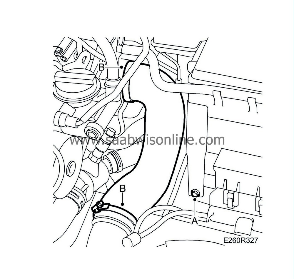
Remove the fuse holder (A) and bend it up. Hold it aside with
83 95 212 Strap
.
|
|
| 15. |
Detach the turbocharger delivery hose (B) between the throttle body and turbocharger delivery pipe.
|
|
| 16. |
Position a jack beneath the gearbox.
|
|
| 17. |
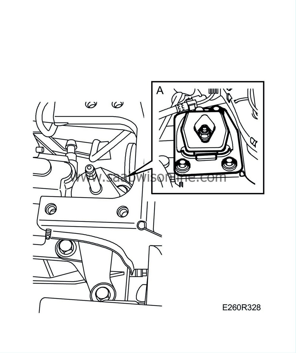
Mark the position of the bolts and remove the left engine pad (A).
|
|
| 18. |
Place a wedge on the subframe and lower the gearbox toward the subframe.
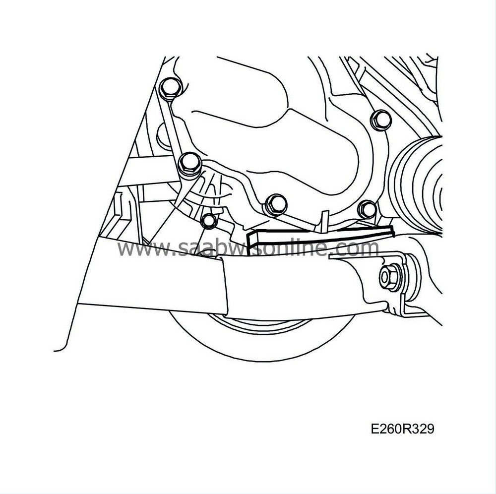
|
|
| 19. |
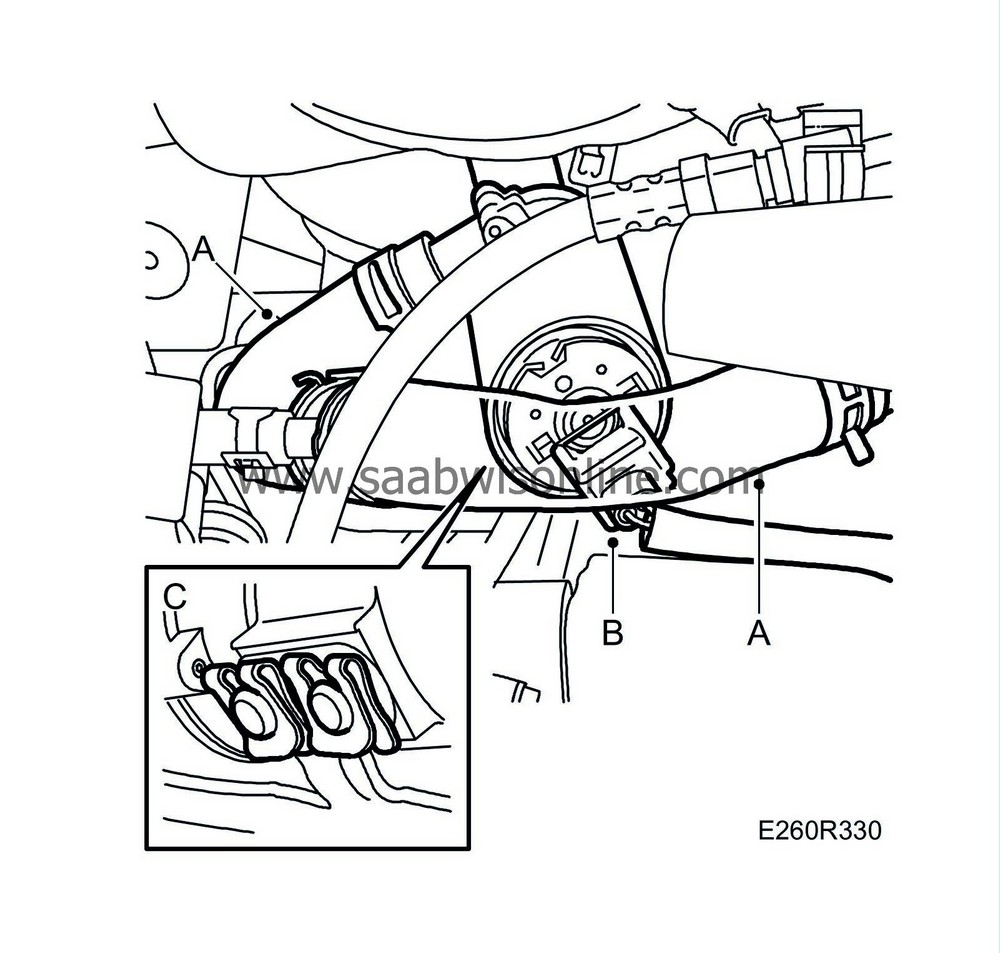
Detach the water hose (A) that runs from the auxiliary heater to the circulation pump. Detach on the heater side. Unplug the connectors (B) of the circulation pump and reversing light switch.
|
|
| 20. |
Remove the clips (C) securing the circulation pump.
|
|
| 21. |
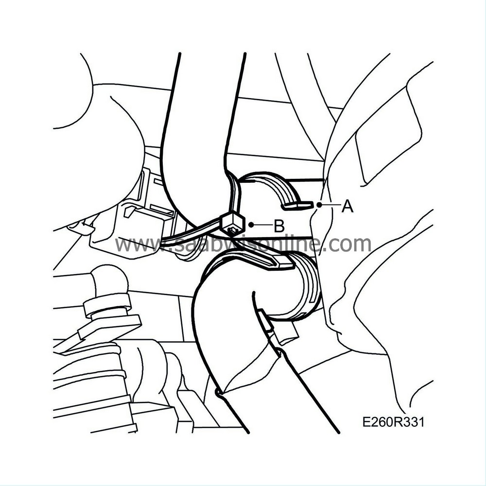
Remove the clip (A) between the hoses and cut off the cable tie (B) holding the auxiliary heater's electrical connection. Move the pump aside.
|
|
| 22. |
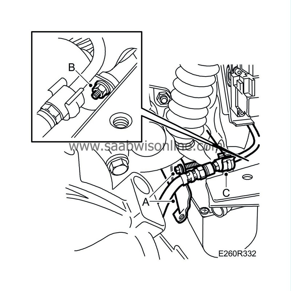
Remove the bolt of the auxiliary heater retaining bracket (A) and remove the bracket. Remove the upper nut (B) of the auxiliary heater bracket.
|
|
| 23. |
Detach the connection pipe from the clip (C).
|
|
| 24. |
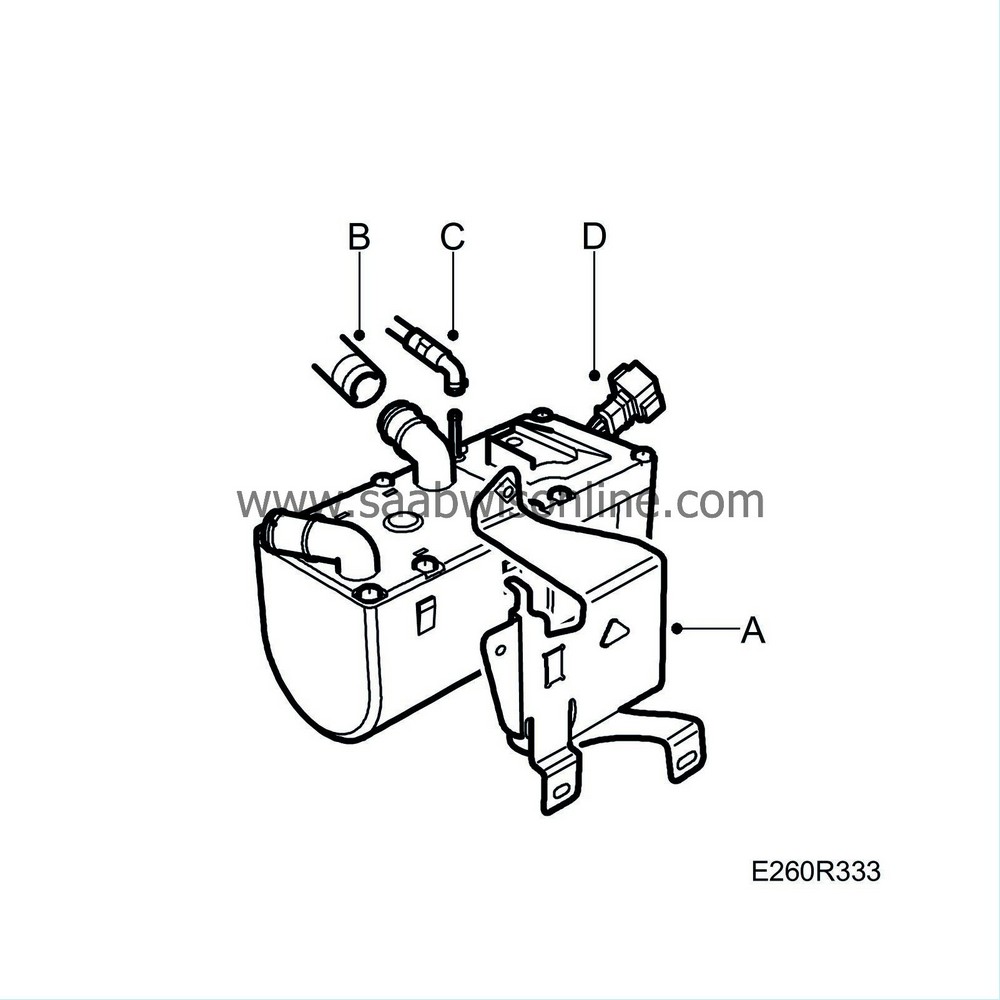
Remove the auxiliary heater and bracket from the structural member, separate the bracket and heater and remove the bracket (A).
|
|
| 25. |
Detach the water hose (B) and fuel hose (C). Unplug the connector (D).
|
|
| 26. |
Hold the connection pipe aside and raise the auxiliary heater.
|
|
| To fit |
| 1. |
Lower the auxiliary heater.
|
|
| 2. |
Attach the water hose (B) and fuel hose (C). Plug in the connector (D).

|
|
| 3. |
Guide the auxiliary heater and its bracket towards the structural member. Fit the bracket (A) with the auxiliary heater to the structural member and fit the two lower nuts.
|
|
| 4. |
Fit the upper nut (B) of the bracket.

|
|
| 5. |
Fit the retaining bracket (A) outside of the auxiliary heater.
|
|
| 6. |
Fit the connection pipe to the clip (C).
|
|
| 7. |
Fit the circulation pump and clips (C).

|
|
| 8. |
Attach the water hose (A) that runs from the circulation pump to the auxiliary heater.
|
|
| 9. |
Fit the circulation pump connector (B).
|
|
| 10. |
Plug in the reversing light connector.
|
|
| 11. |
Fit the clip (A) between the hoses and the cable tie (B) that holds the auxiliary heater's electrical connection.

|
|
| 12. |
Remove the hose pinch-off pliers.
|
|
| 13. |
Pressure test the cooling system. See
Cooling system, pressure testing
.
|
|
| 14. |
Raise the powertrain and fit the engine pad nuts and bolts following the markings made previously (A).
Tightening torque, nut 74 Nm (55 lbf ft) Tightening torque, bolts 60 Nm (45 lbf ft) 
|
|
| 15. |
Remove the jack and the wedge.
|
|
| 17. |
Remove the strap and fit the fuse holder (A).
|
|
| 18. |
Raise the car.
|
|
| 19. |
Fit the intake pipe and exhaust pipe. Turn the intake pipe so it does not touch the exhaust pipe.
|
|
| 20. |
Tighten the clamp (A) on the intake and exhaust pipes.

|
|
| 21. |
Fit the nuts on the exhaust pipe (C).
|
|
| 22. |
Fit the support plate (B).
Tightening torque, subframe bolt 100 Nm +45° (74 lbf ft +45°) Tightening torque, support plate bolts 63 Nm (46 lbf ft) |
|
| 23. |
Fit the torque rod bolt (A).
Tightening torque: 70 Nm + 90° (52 lbf ft + 90°) 
|
|
| 24. |
Fit the left side cover.

|
|
| 25. |
Fit the lower engine cover (A).

|
|
| 26. |
Fit the front left wheel, see
Wheels
.
|
|
| 27. |
Lower the car to the floor.
|
|
| 28. |
Fit the upper engine cover (A).

|
|
| 29. |
Fit the battery (C).
|
|
| 30. |
Fill with coolant (B). See
Filling and bleeding the cooling system
.
|
|
| 31. |
Set the clock.
|
|

 Warning

