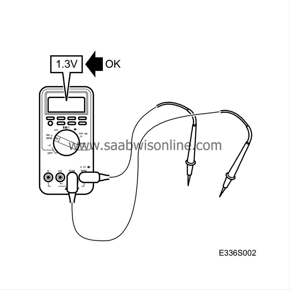
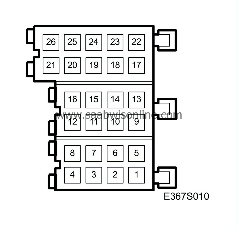
Pin no.
|
Lead colour
|
Component/
Function
|
In/Out
|
Test conditions
|
Across
|
Test reading
|
See
|
1
|
|
No connection
|
|
|
|
|
|
2
|
RD/BU
|
Power supply +15
|
In
|
Ignition ON.
|
2-4
|
B+
|

|
3
|
|
No connection
|
|
|
|
|
|
4
|
BK
|
Ground
|
|
|
4 - good grounding point.
|
<0.5V
|

|
5
|
BK/WH
|
Mute control
|
Out
|
The ignition is switched on.
|
8-5
|
<1 V after approx. 1 sec. B+ for approx. 10 sec.
|
Audio System

|
|
|
|
|
The ignition is switched off.
|
8-5
|
|
|
6
|
YE
|
Telephone mute
|
In
|
No telephone call.
|
6-4
|
4-6 V
|

|
|
|
|
|
Telephone call.
|
6-4
|
<2 V
|
|
7
|
GN
|
Trigger voltage:
|
Out
|
Main unit on.
|
7-4
|
|
Audio System

|
8
|
RD
|
Power supply +30
|
In
|
|
8-4
|
B+
|

|
9
|
BN/RD
|
Line output, rear right (-)
|
Out
|
Music playing.
|
9-4
|
0-2 V AC. Dependent on volume control. The test reading should vary with the volume of the music.
|
Audio System

|
10
|
BU
|
Line output, front right (-)
|
Out
|
Music playing.
|
10-4
|
0-2 V AC. Dependent on volume control. The test reading should vary with the volume of the music.
|
Audio System

|
11
|
RD/WH
|
Line output, front left (-)
|
Out
|
Music playing.
|
11-4
|
0-2 V AC. Dependent on volume control. The test reading should vary with the volume of the music.
|
Audio System

|
12
|
OG/WH
|
Line output, rear left (-)
|
Out
|
Music playing.
|
12-4
|
0-2 V AC. Dependent on volume control. The test reading should vary with the volume of the music.
|
Audio System

|
13
|
GY
|
Line output, rear right (+)
|
Out
|
Music playing.
|
13-4
|
0-2 V AC. Dependent on volume control. The test reading should vary with the volume of the music.
|
Audio System

|
14
|
RD
|
Line output, front right (+)
|
Out
|
Music playing.
|
14-4
|
0-2 V AC. Dependent on volume control. The test reading should vary with the volume of the music.
|
Audio System

|
15
|
BU/WH
|
Line output, front left (+)
|
Out
|
Music playing.
|
15-4
|
0-2 V AC. Dependent on volume control. The test reading should vary with the volume of the music.
|
Audio System

|
16
|
YE/WH
|
Line output, rear left (+)
|
Out
|
Music playing.
|
16-4
|
0-2 V AC. Dependent on volume control. The test reading should vary with the volume of the music.
|
Audio System

|
17
|
WH
|
I-BUS (-)
|
In/Out
|
Ignition ON.
|
17-4
|
2-3 V
|

|
18
|
GN
|
I-BUS (+)
|
In/Out
|
Ignition ON.
|
18-4
|
2-3 V
|

|
19
|
|
No connection
|
|
|
|
|
|
20
|
BK
|
CD changer RH line input (-)
|
In
|
Music playing.
|
20-21
|
0-2 V AC. The test reading should vary with the volume of the music.
|
Audio System
|
21
|
BN
|
CD changer RH line input (+)
|
In
|
Music playing.
|
21-20
|
0-2 V AC. The test reading should vary with the volume of the music.
|
Audio System
|
22
|
BK
|
Phone line input, ground
|
In
|
|
|
|

|
23
|
GY/WH
|
Phone line input, signal
|
In
|
|
|
|

|
24
|
|
No connection
|
|
|
|
|
|
25
|
RD/WH
|
CD changer LH line input (-)
|
In
|
Music playing.
|
25-26
|
0-2 V AC. The test reading should vary with the volume of the music.
|
Audio System
|
26
|
BU/WH
|
CD changer RH line input (+)
|
In
|
Music playing.
|
26-25
|
0-2 V AC. The test reading should vary with the volume of the music.
|
Audio System
|


