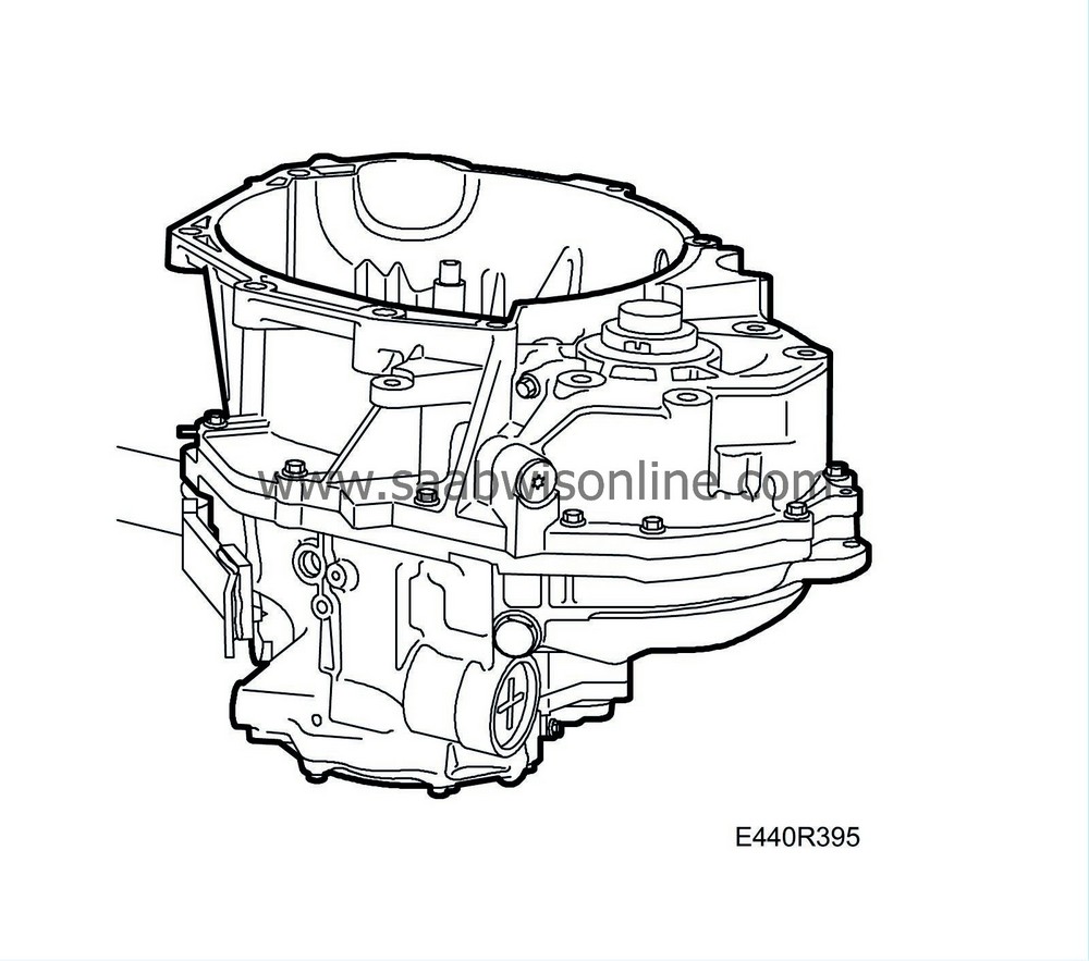
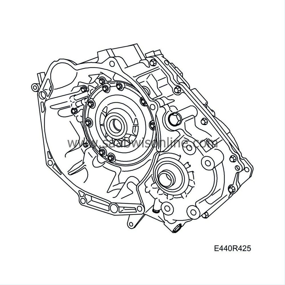
Gearcase and torque converter housing
|
|
Gearcase and torque converter housing
|
|
Important
|
|
It is essential the greatest cleanliness is maintained when working with the transmission. Contamination can seriously affect the transmission's function and service life.
|
|
|
To dismantle
|
1.
|
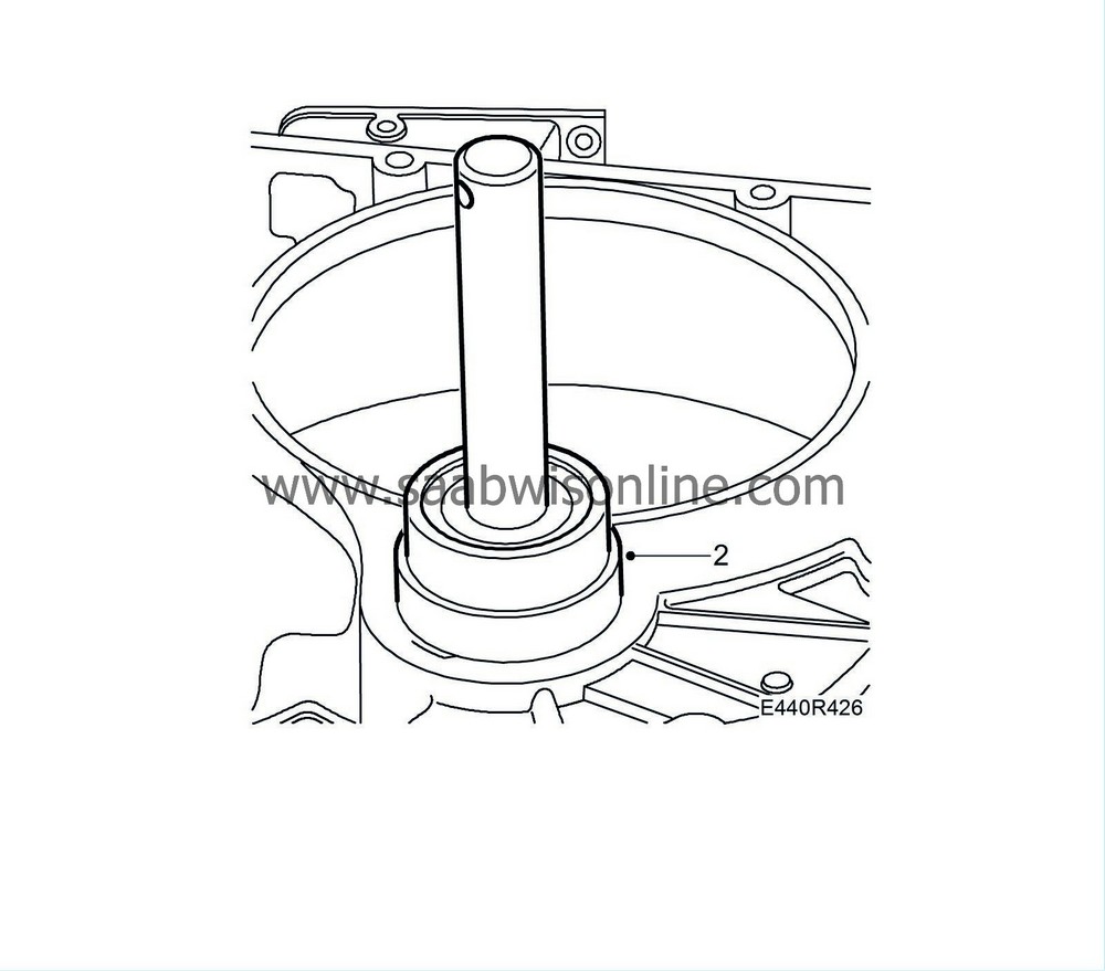
Drain the oil from the transmission in the car before starting removal. Remove the gearbox from the car. See removing gearbox assembly. Fit the dipstick pipe.
|
|
3.
|
Remove the dipstick pipe.
|
|
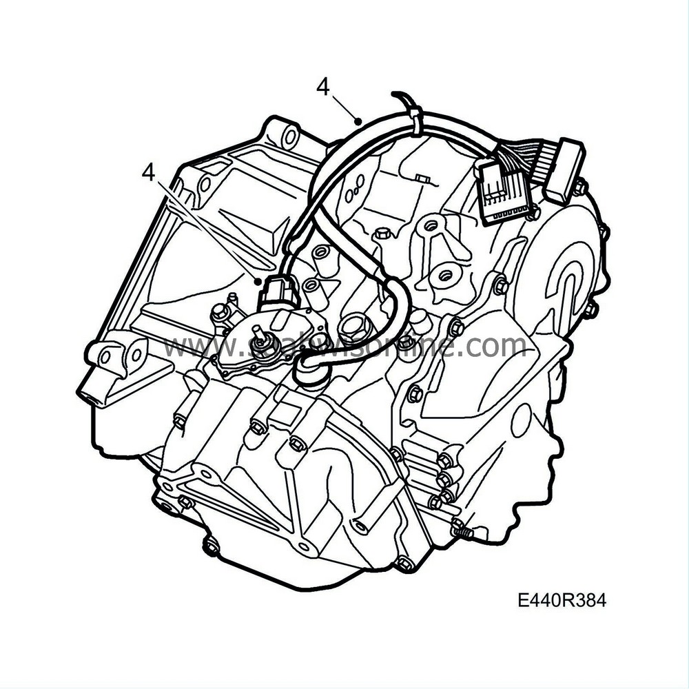
4.
|
Unplug the connector from the gear selector position sensor and speed sensor.
|
|
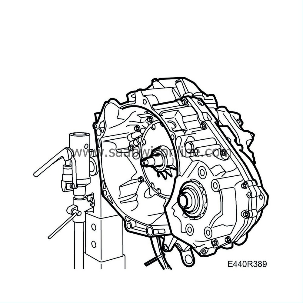
5.
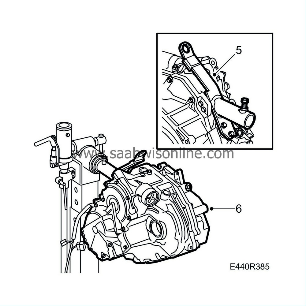
|
Fit
87 92 392 Holder, transmission
to the transmission using M8x25 flange screws.
|
Note
|
|
Organise the workplace so that groups of associated parts that are dismantled can be kept together to facilitate refitting.
|
|
|
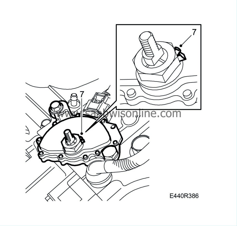
7.
|
Bend out the lock washer for the gear position sensor nut and loosen the nut slightly.
|
|
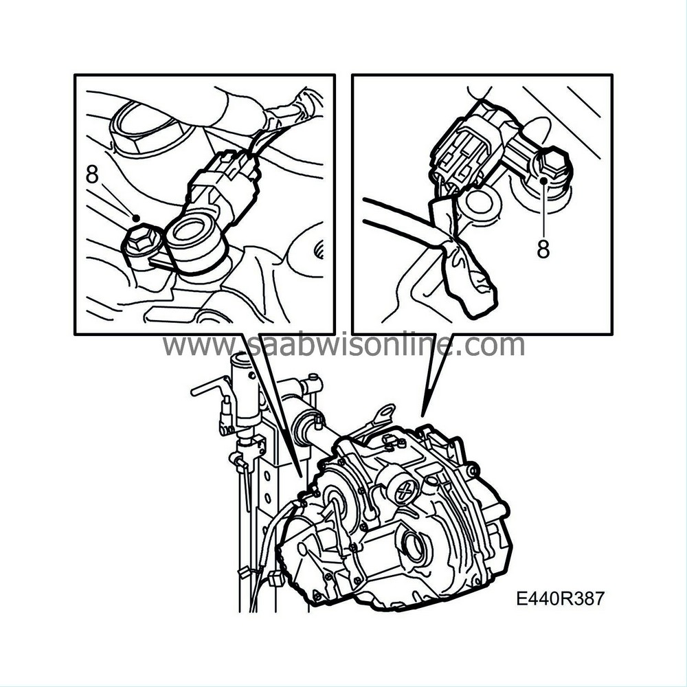
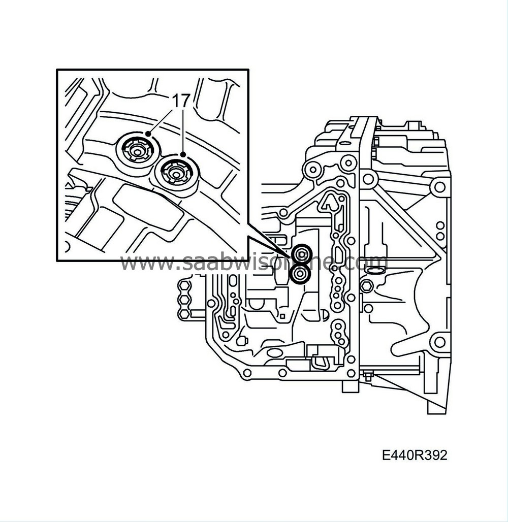
8.
|
Remove the speed sensors.
|
|
9.
|
Remove the gear position sensor.
|
|
11.
|
Turn the gearbox through 180° in the stand.
|
|
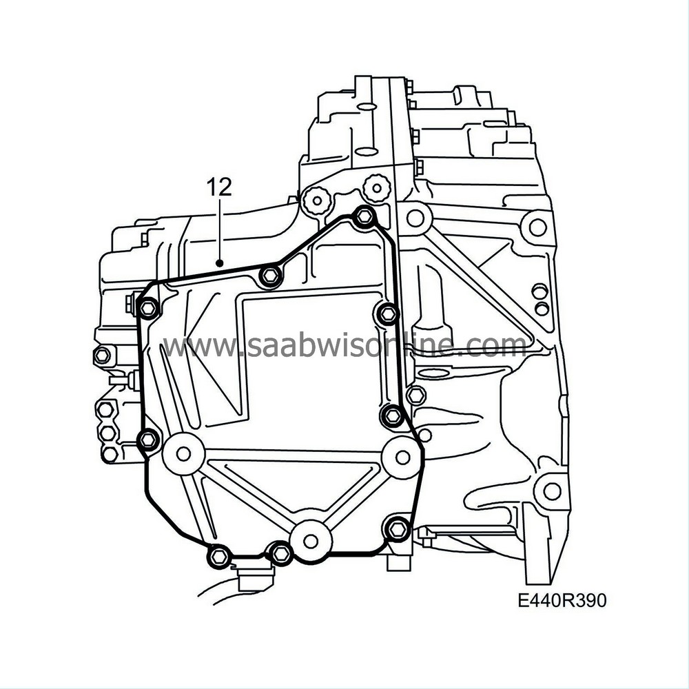
12.
|
Remove the bolts securing the valve body cover and knock loose the cover using a plastic mallet.
|
Important
|
|
Take care so as not to damage the sealing surfaces.
|
|
|
|
|
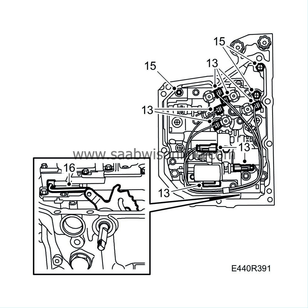
13.
|
Disconnect the electrical connectors of the solenoids. Lift the casing of the system pressure solenoids (SLS, SLT and SLU) slightly with a small screwdriver to release the catch. Disconnect the oil temperature sensor.
|
|
14.
|
Release the cable. Pull the cable and grommet out of the gear case. Place the holder to one side.
|
|
15.
|
Remove the valve body bolts (only bolts with 10 mm head). Retain the small cover.
|
|
16.
|
Unhook the manual valve connecting rod from the valve control and remove the valve body.
|
|
17.
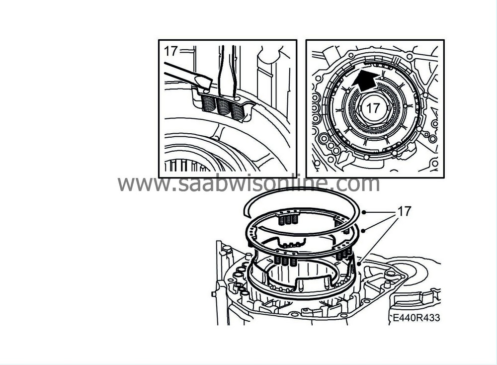
|
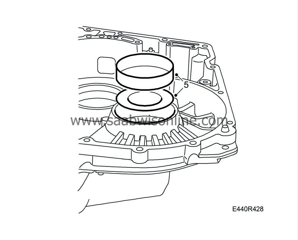
Remove the two seals.
|
|
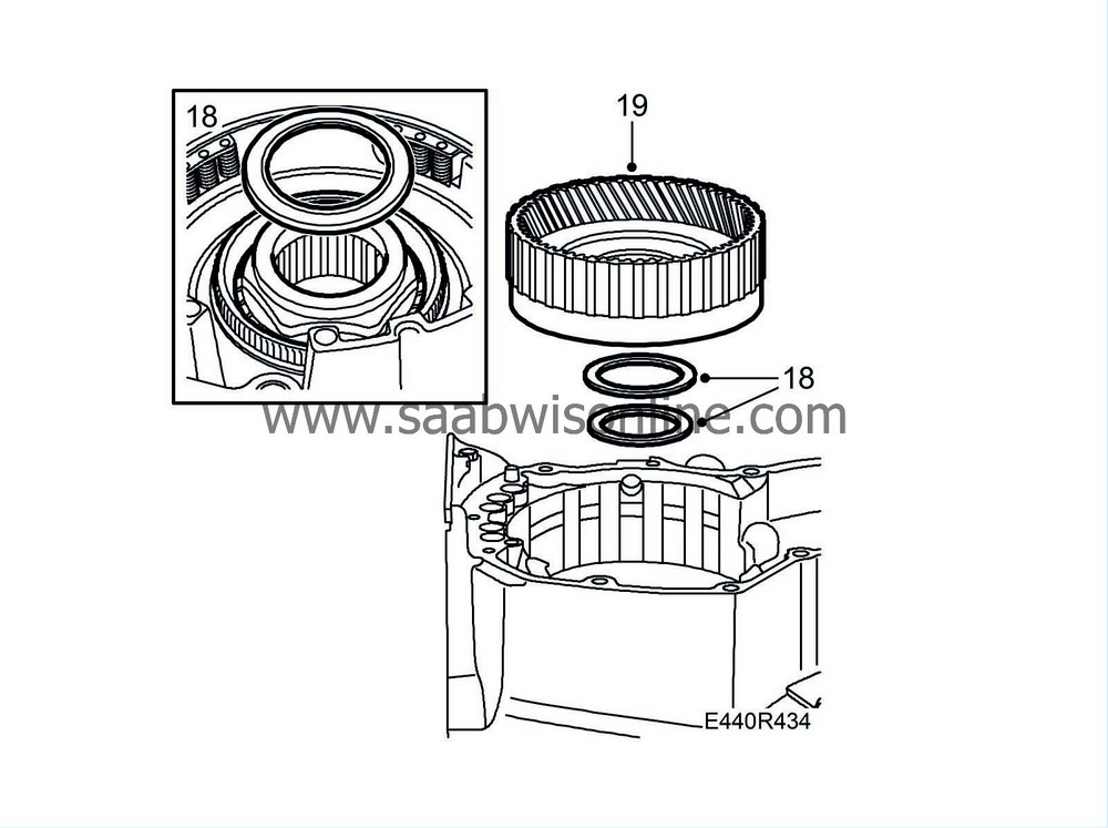
18.
|
Remove the bolts securing the oil pump to the gearcase.
|
|
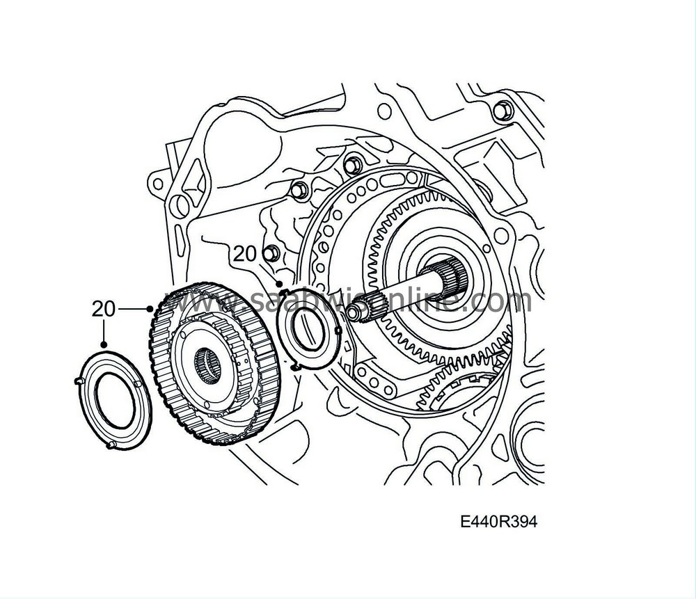
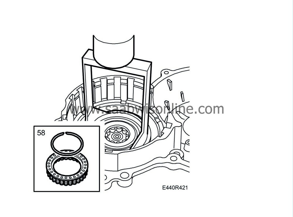
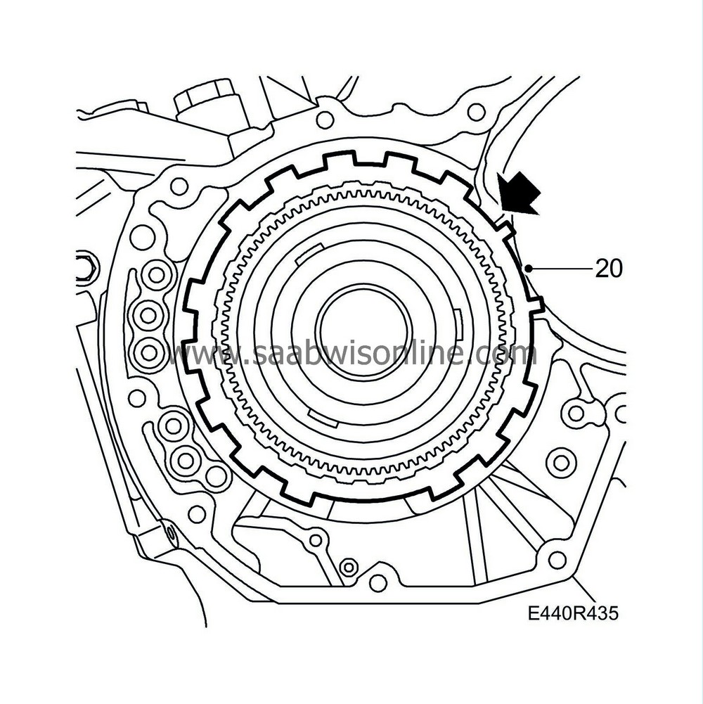
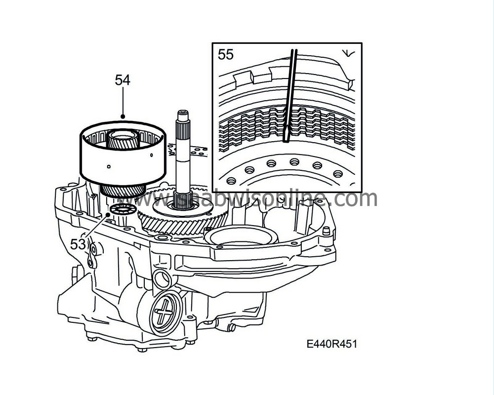
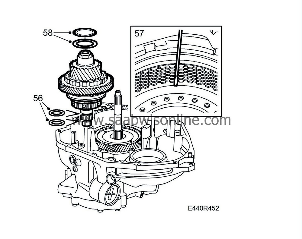
20.
|
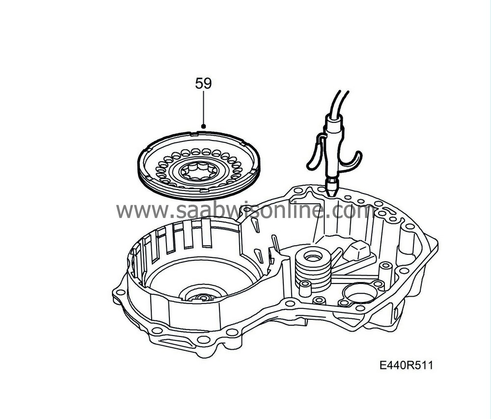
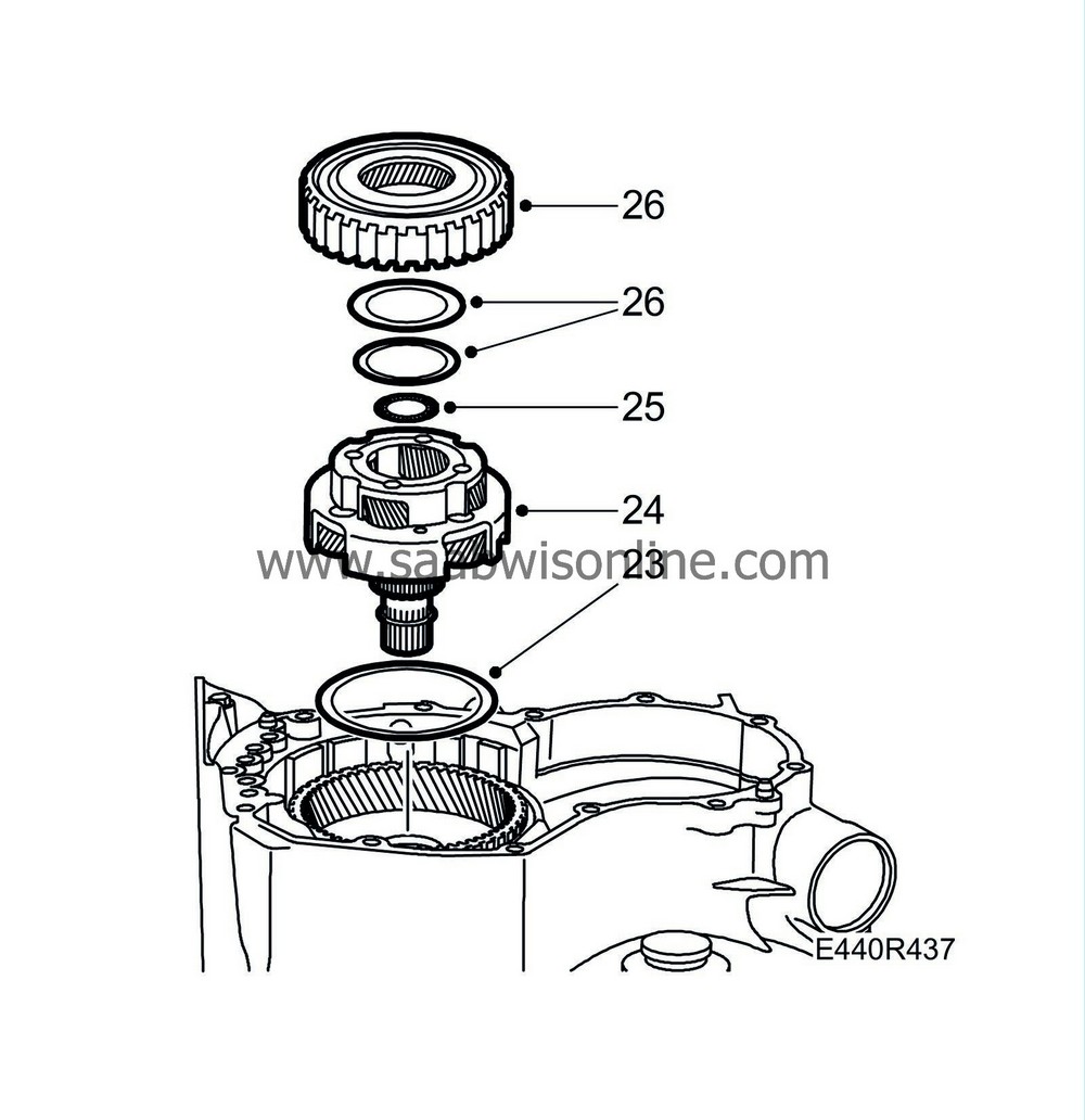
Remove the brake hub and freewheel F1.
|
|
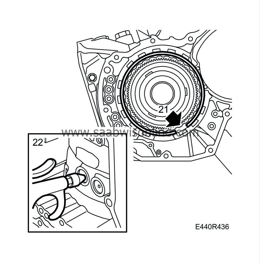
21.
|
Turn the gearbox through 90° in the stand.
|
|
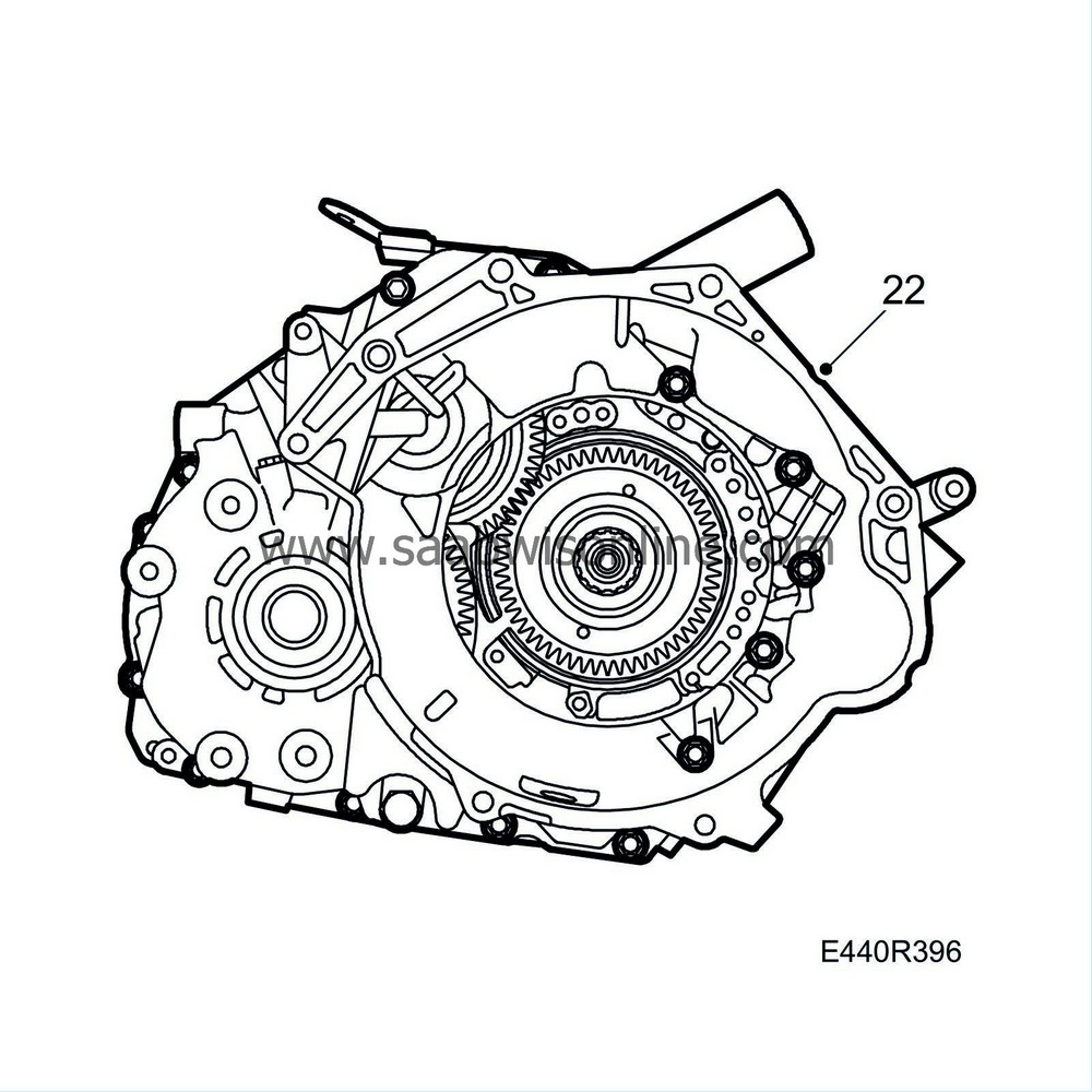
22.
|
Remove the torque converter housing.
|
|
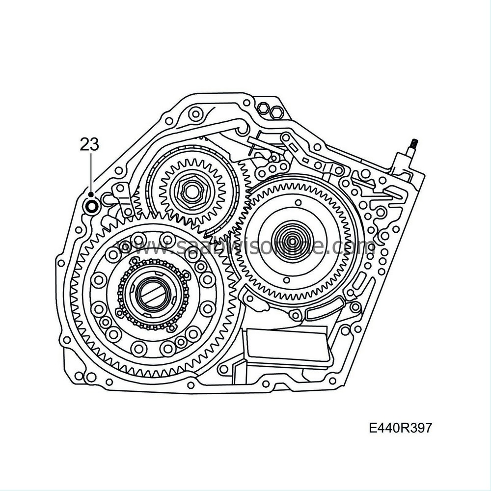
23.
|
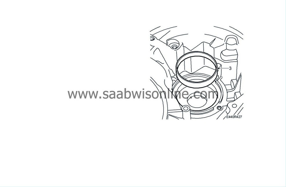
Knock loose the housing using a plastic mallet. Remove the seal.
|
|
24.
|
Lift out the differential unit.
|
|
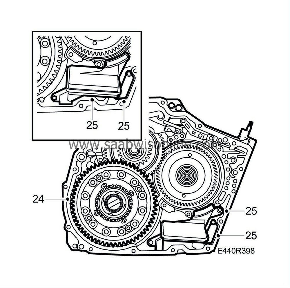
25.
|
Remove the oil strainer and the cover plate.
|
|
26.
|
Remove the oil channel plate from the gearcase.
|
|
27.
|
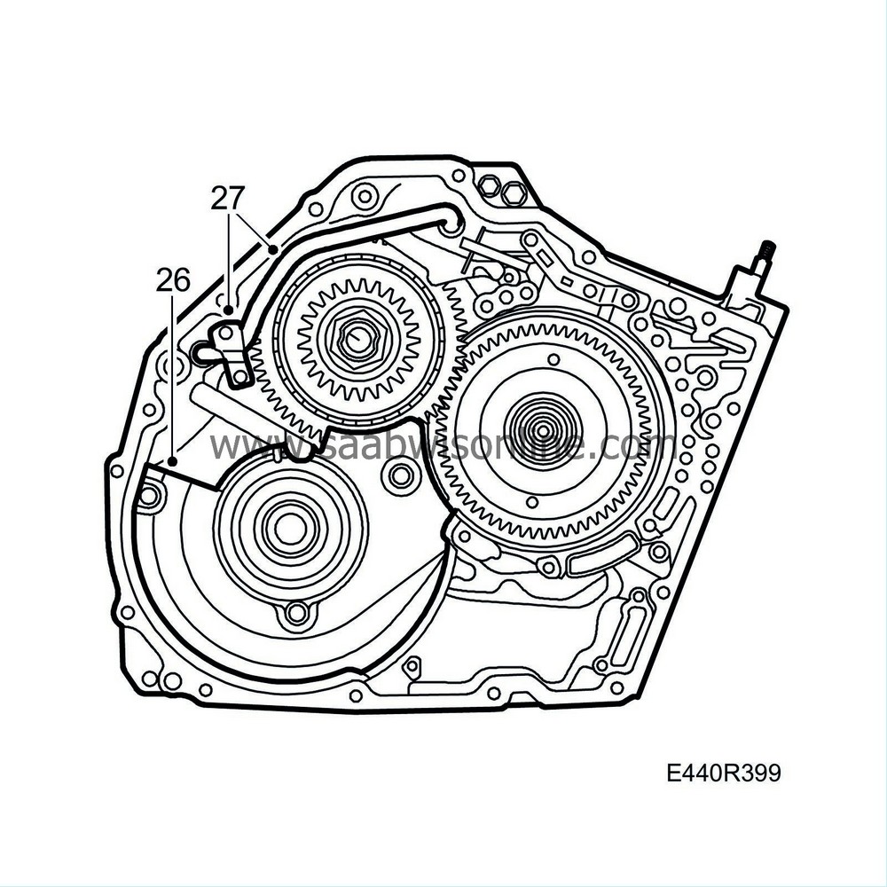
Remove the oil delivery pipe and holder.
|
|
28.
|
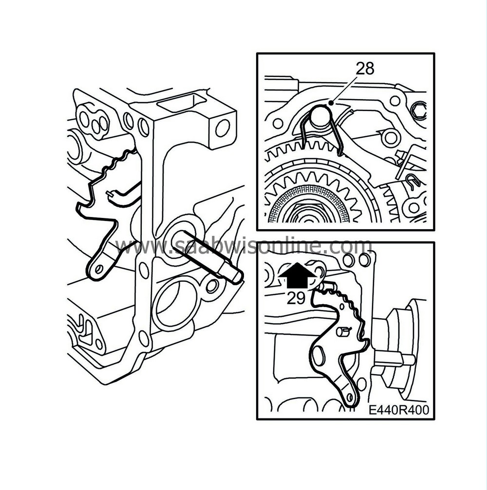
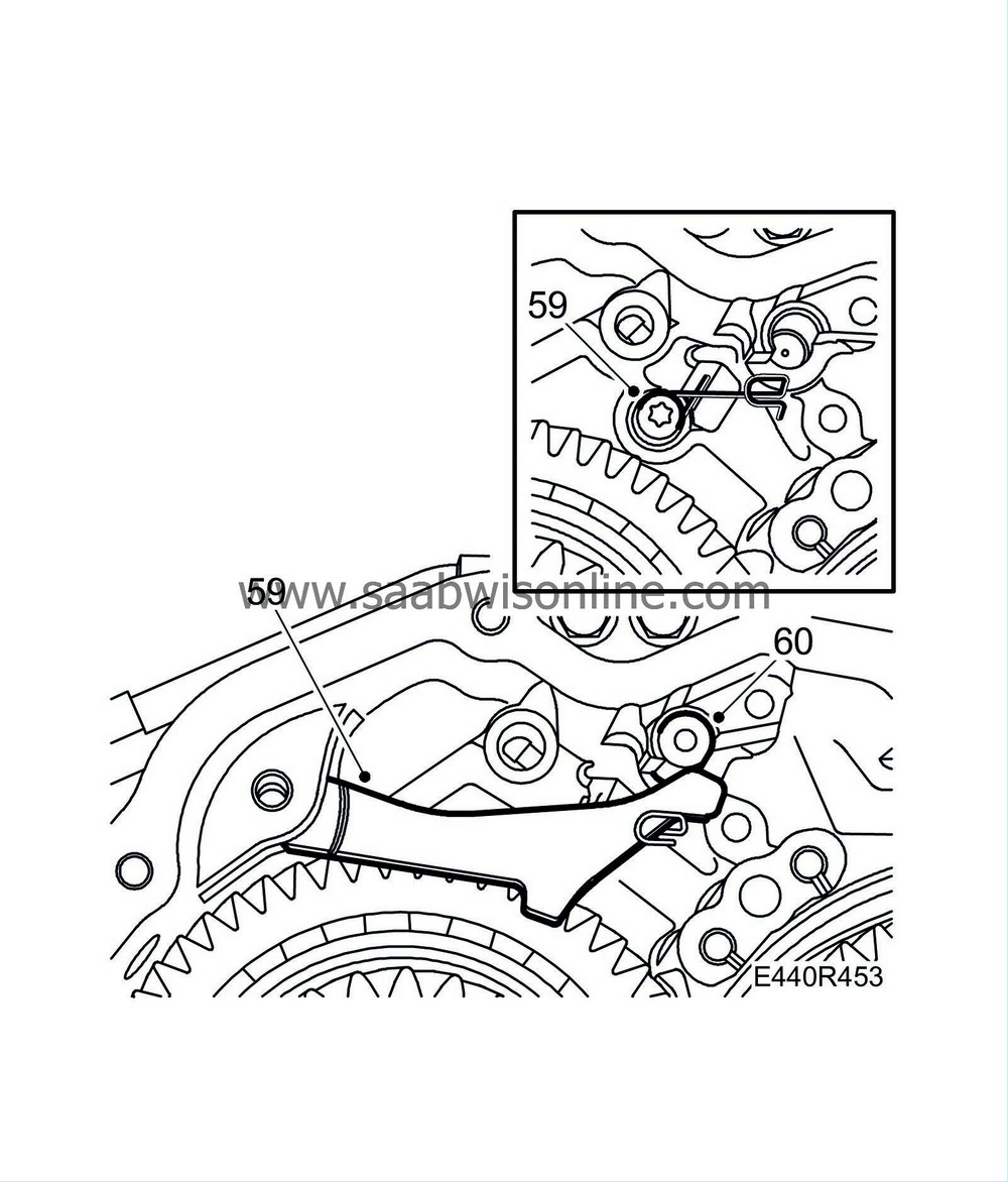
Remove the torsion spring and the ratchet spindle for the handbrake.
|
|
29.
|
Remove the handbrake control rod and the gear position disc. Release the detent spring.
|
|
30.
|
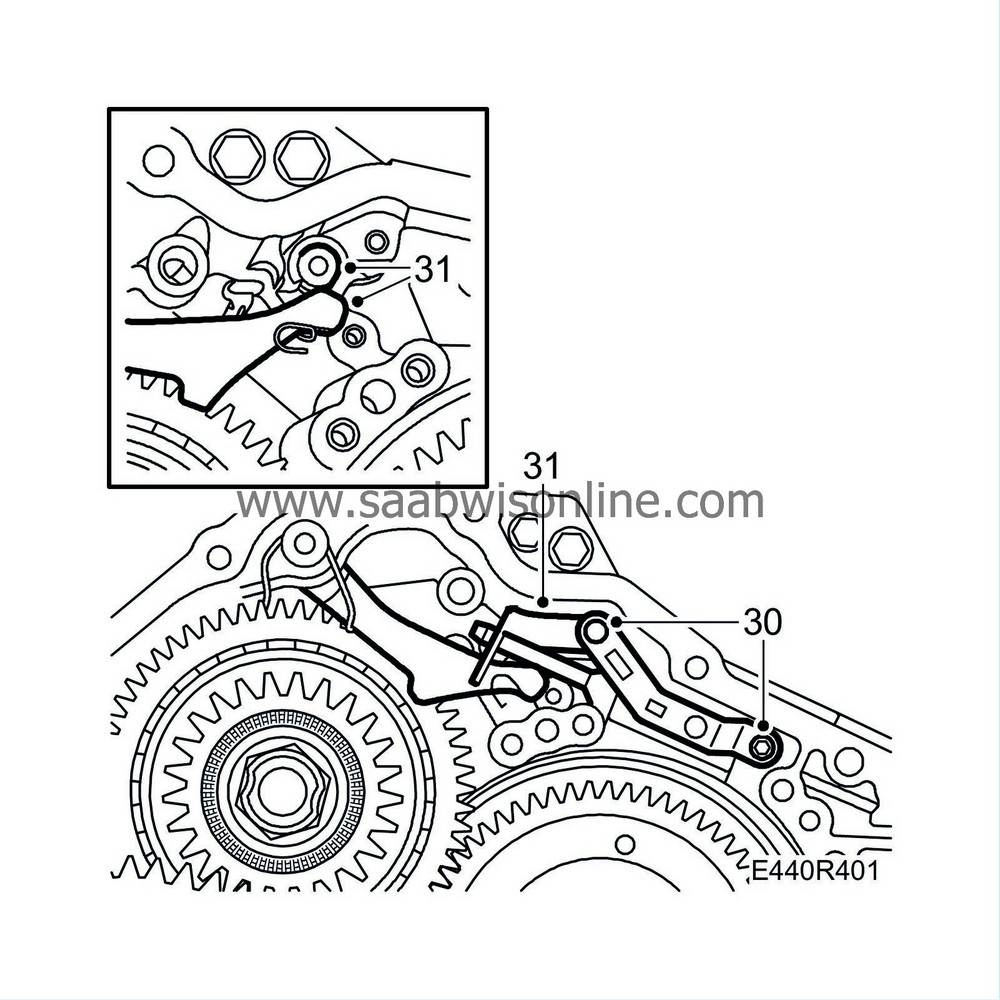
Remove the holder for the handbrake control rod and the detent spring.
|
|
31.
|
Remove the handbrake ratchet, guide pin and torsion spring.
|
|
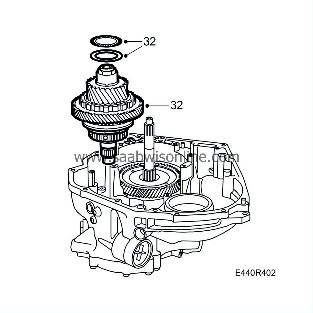
32.
|
Lift out the output shaft complete with thrust bearing and bearing race.
|
|
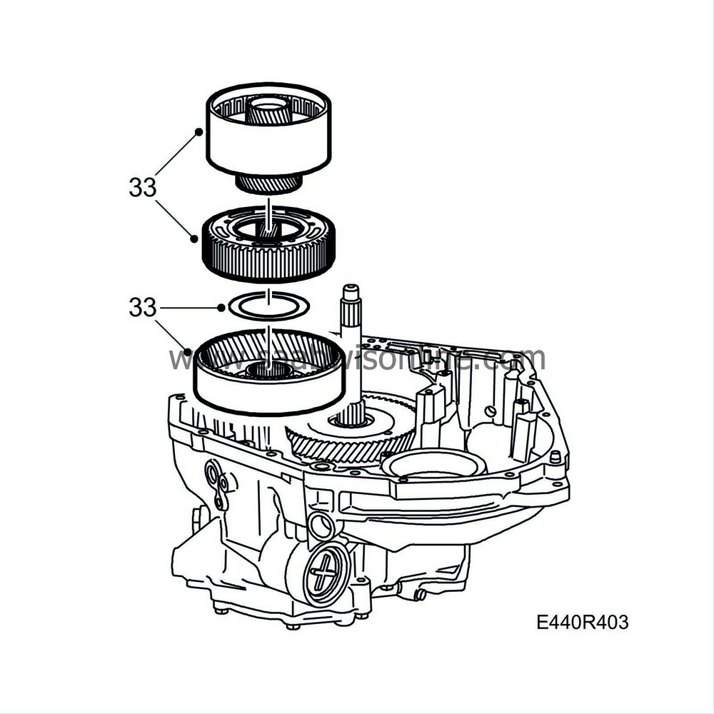
33.
|
Lift out the C3 clutch and bearing race, and the planetary gear assembly. Retain the thrust bearing.
|
|
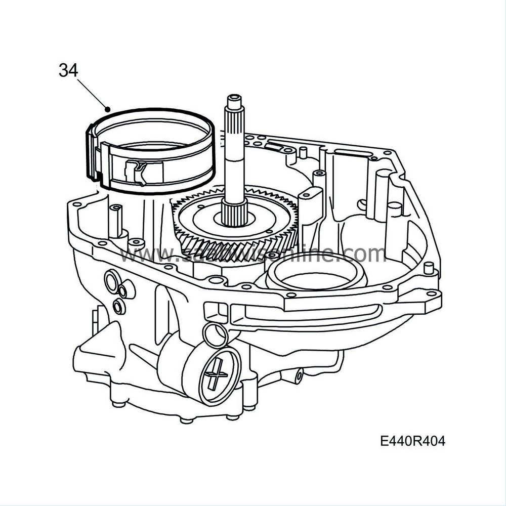
34.
|
Lift out the B4 brake bands from the gearcase.
|
|
35.
|
Turn the gearbox through 180°
|
|
36.
|
Remove the bolts securing the end plate. Knock loose the cover with a plastic mallet. Remove the five seals.
|
|
37.
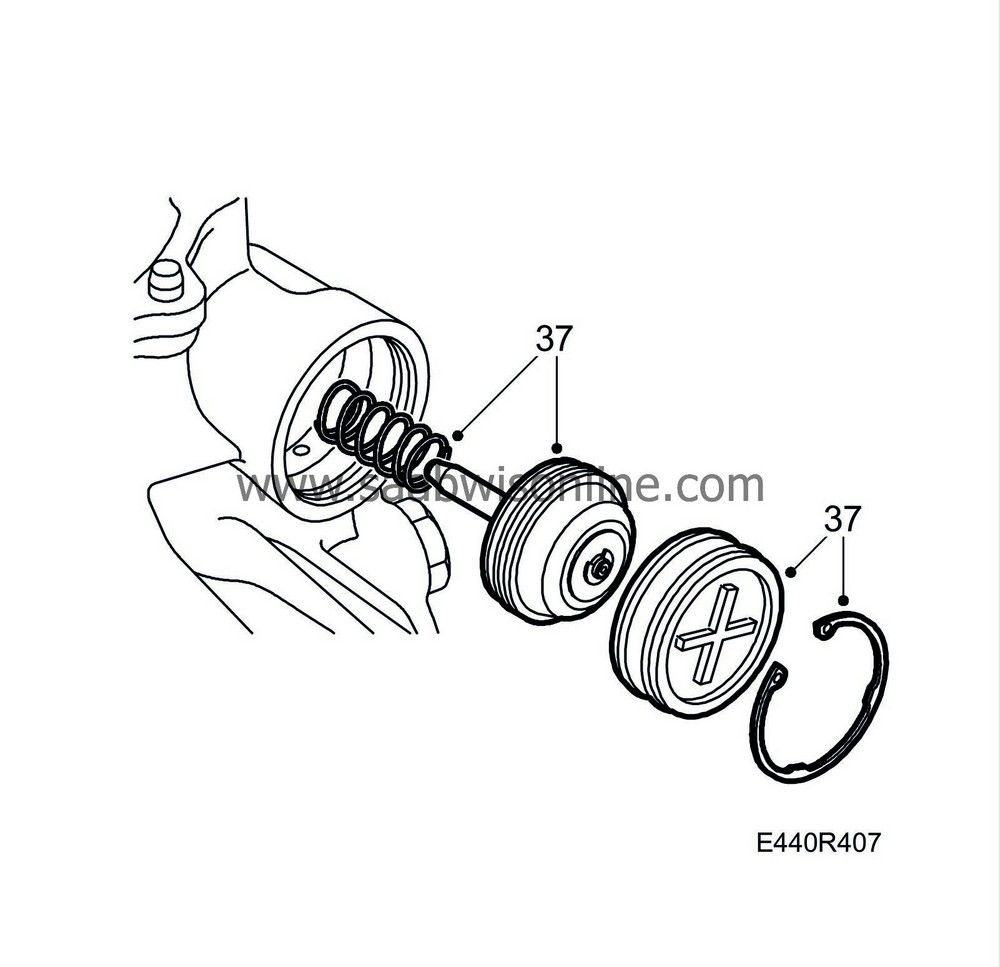
|
Remove the circlip, cover, plunger, spring and the two O-rings for the B4 brake plunger. NB. Take care as the spring can thrust off the cover and plunger.
|
|
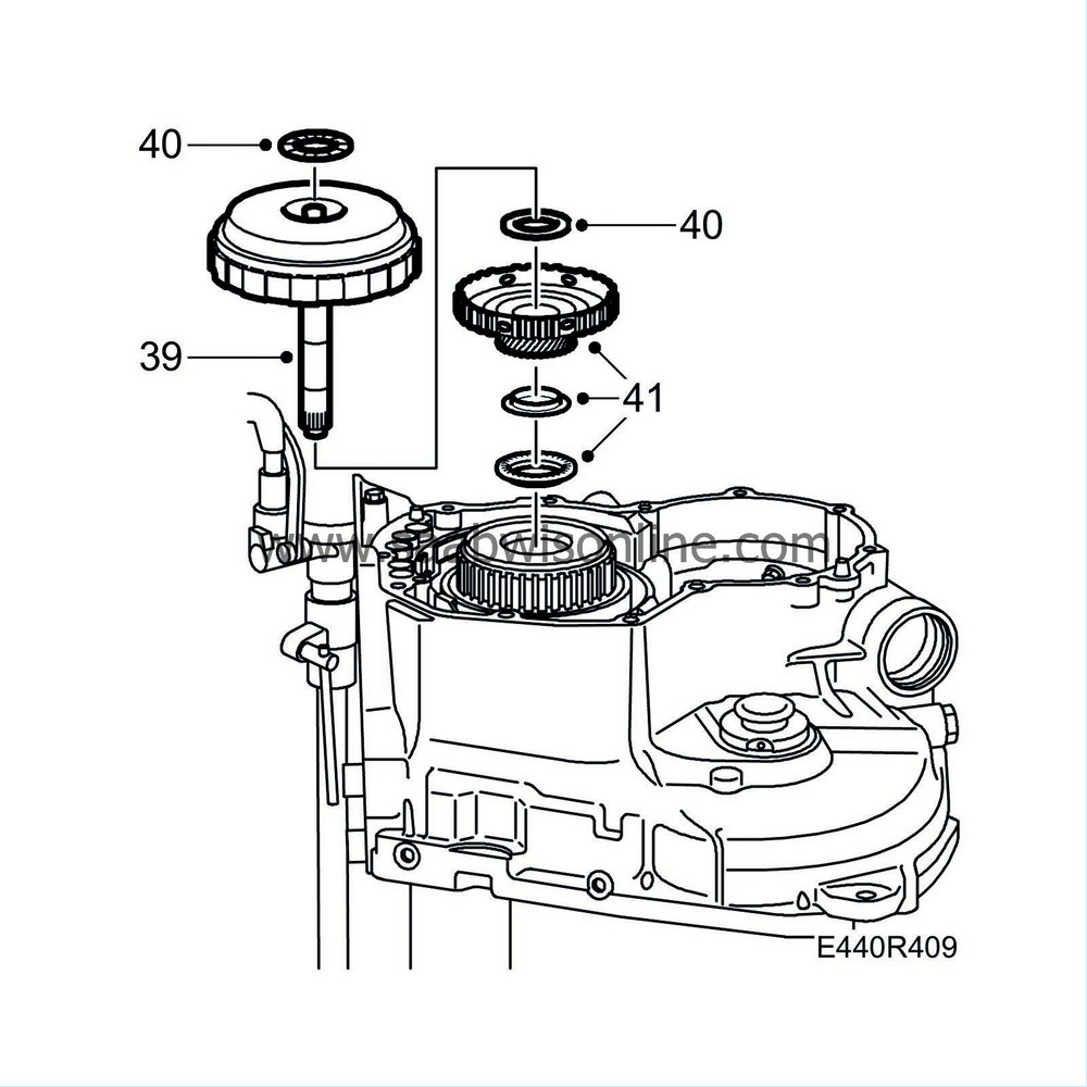
39.
|
Lift out the turbine shaft unit with clutches C1 and C2. Retain the thrust bearing and thrust bearing race.
|
|
40.
|
Remove the bearing race from the turbine shaft unit and clutches C1 and C2.
|
|
41.
|
Lift out the planetary gear sun gear and thrust bearing. Retain the bearing race.
|
|
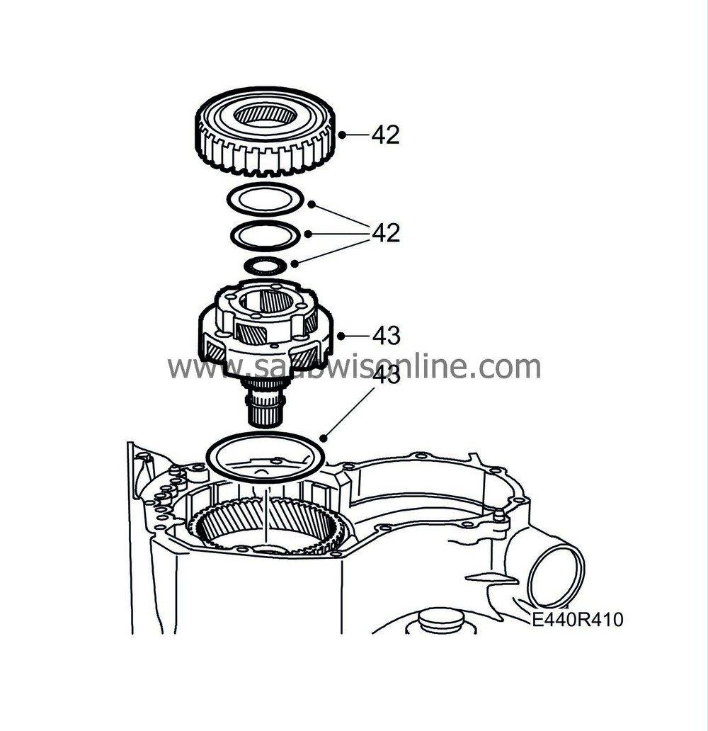
42.
|
Remove the rear ring gear. Retain the thrust bearing and bearing race.
|
|
43.
|
Lift out the planetary gear unit with the large thrust bearing.
|
|
44.
|
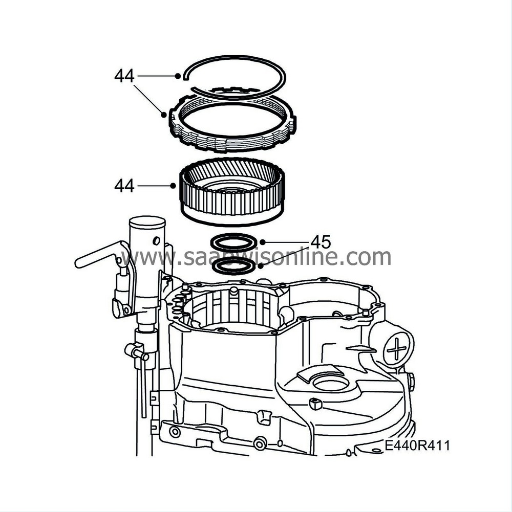
Remove the circlip for freewheel F2 and brake B3 using a screwdriver. Lift out the ring gear with F2 and B3 that contain the clutch discs, disc plates and flange.
|
|
45.
|
Retain the thrust bearing and bearing race.
|
|
46.
|
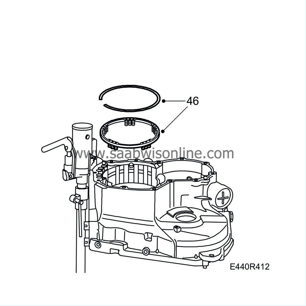
Remove the circlip for the spring unit using a screwdriver. Lift out the spring unit.
|
|
47.
|
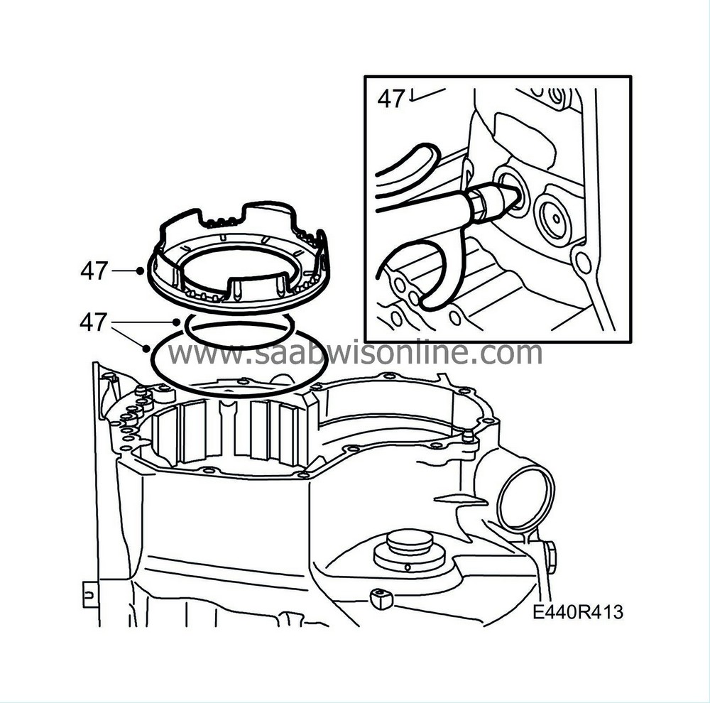
Carefully apply an air pressure of 4 bar through the oil passage for B3 to remove the B3 plunger as illustrated. Use a pair of blunt nose pliers if the plunger will not come out.
|
|
48.
|
Turn the gearbox through 90°.
|
|
50.
|
Turn the gearbox through 90°
|
|
51.
|
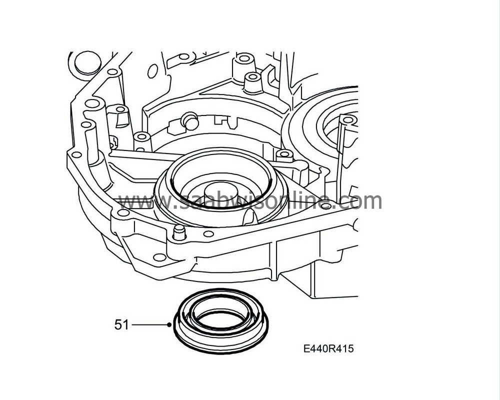
Remove the drive shaft seal using a hammer and drift.
|
|
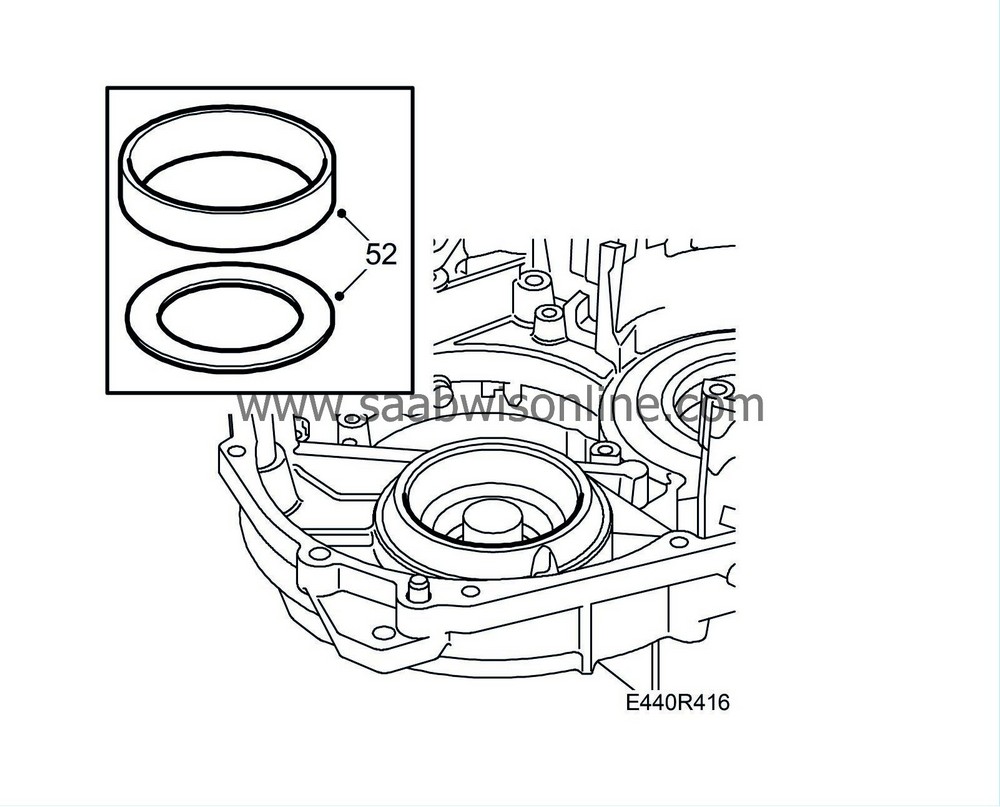
52.
|
Fit
87 91 683 Puller
and
87 91 675 Puller
and remove the bearing race from the gearcase by heating the gearcase with a heat gun for approx. 5 min. Pull out the bearing race and place the shim to one side.
|
|
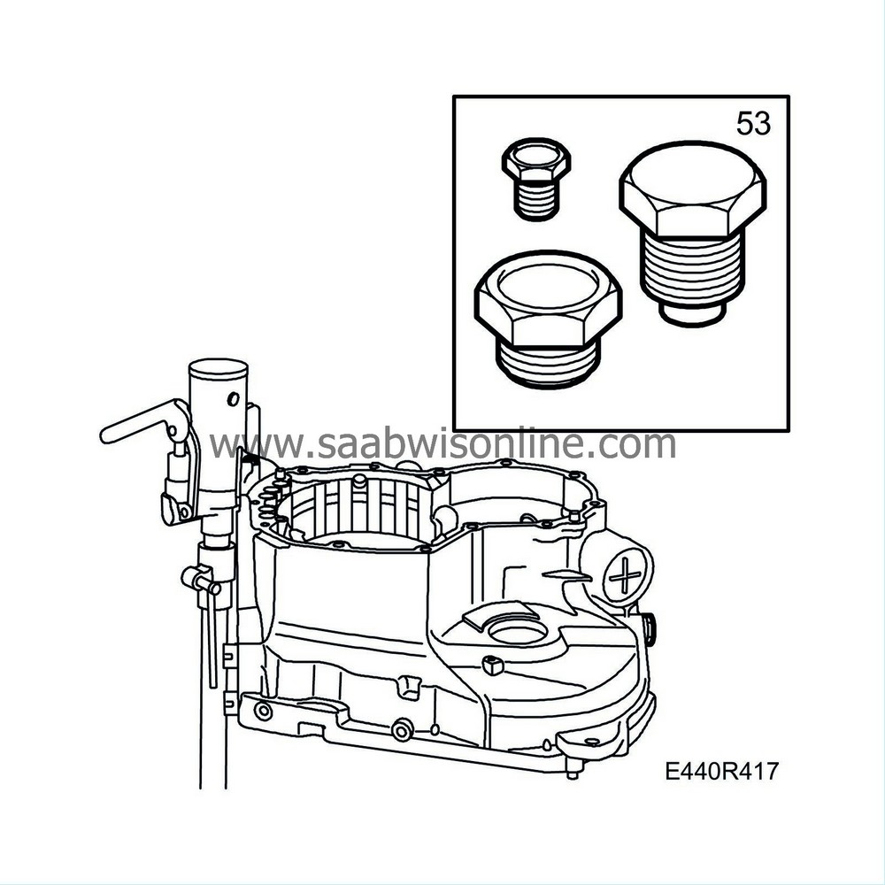
53.
|
If necessary, remove the brake band holder and the remaining plugs from the gearcase. (Do not mix up the plugs.)
|
|
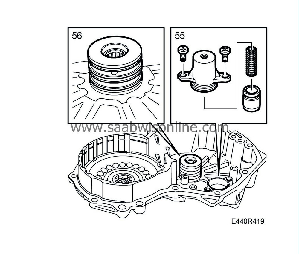
55.
|
If necessary, remove the accumulator for C1 from the end plate with spring and plunger.
|
|
56.
|
Remove the oil sealing rings.
|
|
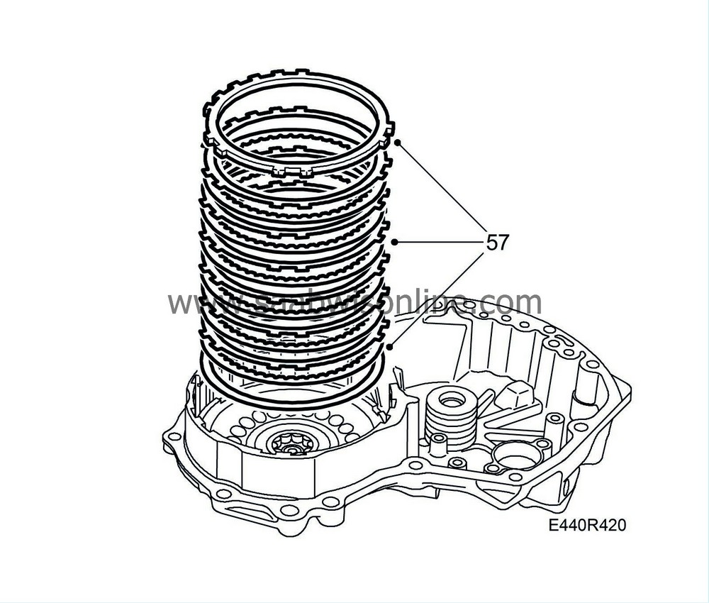
57.
|
Remove the circlip and lift out the clutch assembly from the end plate.
|
|
58.
|
Place the end plate in a hydraulic press. Position
87 91 535 Press ring
and depress the spring assembly slightly so that the circlip can be removed. Use
87 90 180 Pliers
. Lift out the spring assembly.
|
|
59.
|
Apply an air pressure of approx. 4 bar to the hole and press our the piston from the end plate. If necessary, use needle nosed pliers to remove.
|
|
60.
|
Remove all plugs from the end plate.
|
|
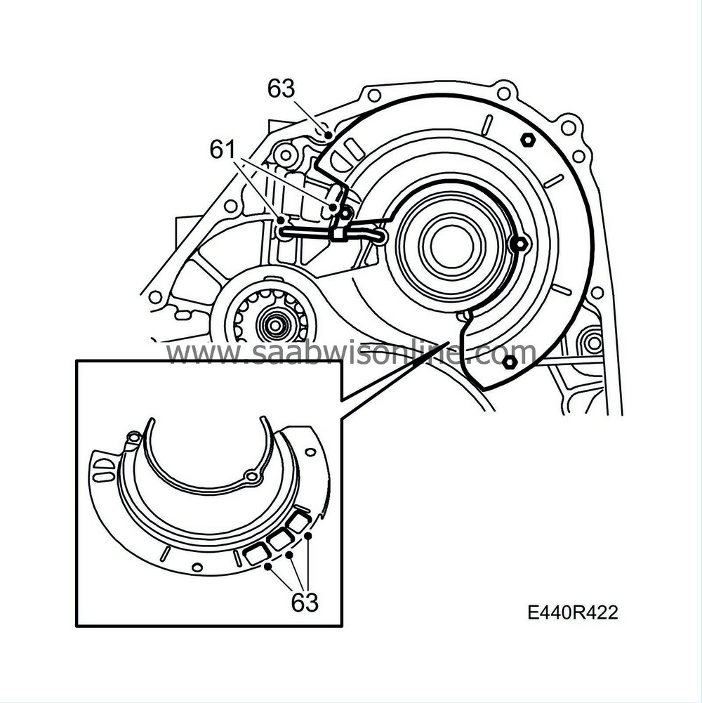
61.
|
Remove the screw and pipe clamp from the torque converter housing.
|
|
63.
|
Remove the oil duct plate. Remove the three magnets.
|
|
65.
|
Knock out the shaft seal.
|
|
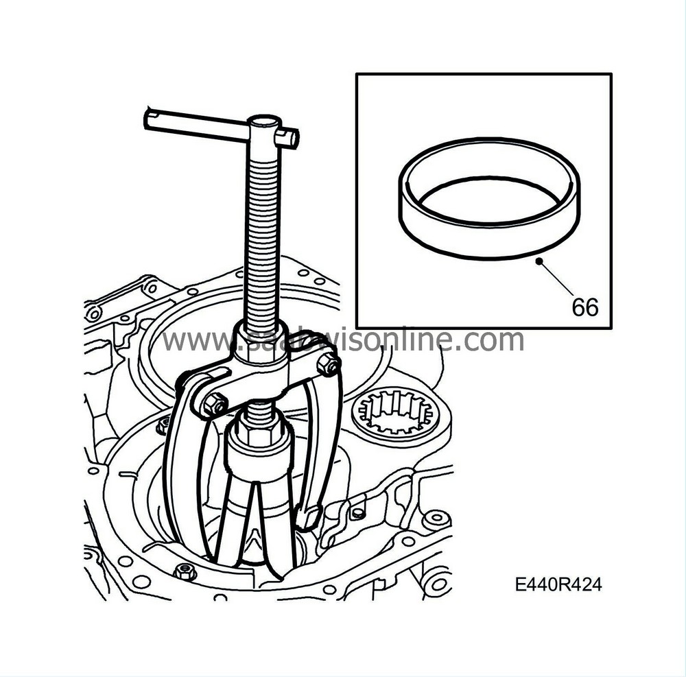
66.
|
Remove the bearing race of the conical roller bearing in the torque converter housing by heating around the bearing seat with a heat gun for about 5 minutes. Pull out the bearing using
87 91 683 Puller
and
87 91 675 Puller
. The bearing need only be removed if the torque converter housing or differential bearing is changed.
|
|
1.
|
If changing the torque converter housing, transfer the outer plugs to the new housing. Carefully remove the old sealing compound from the sealing surface using a gasket scraper and wash the torque converter housing.
|
|
2.
|
Heat the bearing seat with a heat gun and tap the roller bearing into the torque converter housing using
87 90 461 Sleeve, bearing ring
and
83 90 189 Drift
. Press in the bearing with the text facing downwards until it reaches the bottom of the torque converter housing. The side of the roller bearing forms the bearing race of the output shaft's thrust bearing. Remove the sealing ring before heating and fit a new ring once the bearing is in place.
|
|
3.
|
Heat the bearing seat for the differential bearing race in the torque converter housing. Fit the bearing race. Make sure the bearing race is all the way home.
|
|
4.
|
Fit the oil duct plate and the three magnets. Blow the pipe clean, apply vaseline to the ends of the pipe and fit the pipe using a splinter-free plastic mallet. Take care not to bend or damage the pipe. Fit the pipe clip.
|
|
5.
|
Heat the bearing seat for the differential bearing race in the gearcase for about 5 min. Refit the shim and fit the bearing race. Make sure the bearing race is all the way home.
|
|
6.
|
Lubricate the bearings with automatic transmission fluid.
|
|
7.
|
Fit the differential and fit the torque converter housing. Only fit every other bolt. Fit a
87 92 483 Torque wrench
and
87 91 337 Driver, measuring differential bearing torque
to the differential housing (file down the key slightly if the tool does not fit the differential shaft). Turn until the reading is stable.
|
Important
|
|
Inspect the inside of the differential housing for damage. Check also the surfaces of the drive shafts.
|
|
|
Tightening torque 24 Nm (18 lbf ft)
Measure the prestress. Start value:
New bearing
|
1.0 Nm (7 lbf ft)
|
Refitted bearing
|
0.5 Nm (3.5 lbf ft)
|
|
|
8.
|
If the prestress is not within specified limits, remove the differential and bearing race from the gearcase and change shim. If the reading exceeds the specified value, change to a thinner shim. If the reading is lower than the specified value, change to a thicker shim. Shims are available between 1.0 - 1.90 mm in small intervals.
|
|
9.
|
Remove the torque converter housing and lift out the differential.
|
|
10.
|
Turn the gearbox through 90°.
|
|
11.
|
Fit new O-rings on the B4 brake plunger and plunger cover. Lubricate with petroleum jelly and fit the servo plunger with cover. Fit the circlip.
|
|
12.
|
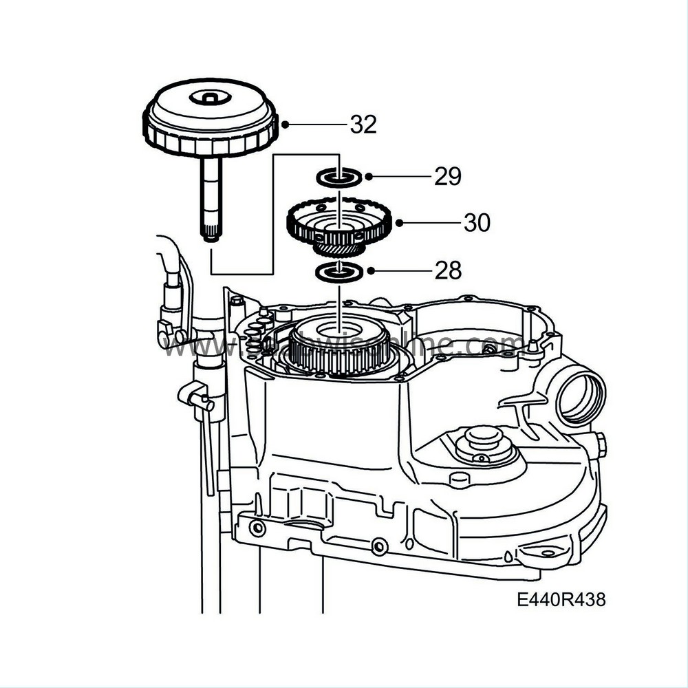
Put in place the intermediate gear assembly in the gearcase.
|
|
13.
|
Turn the gearbox through 90°.
|
|
15.
|
Turn the gearbox through 90°.
|
|
16.
|
Apply petroleum jelly to two new O-rings for brake B3 and fit them on the brake plunger. Take care not to damage the O-rings. Press the plunger into the gearcase.
|
|
17.
|
Put in place the return spring unit on the plunger and fit the circlip in the groove on the gearcase. Make sure the opening in the circlip is not aligned with the large recess. Use a screwdriver to make sure the entire circlip is in the groove.
|
|
18.
|
Lay the bearing race and thrust bearing on the intermediate gear hub.
|
|
19.
|
Fit the front ring gear and freewheel F1. Make sure the thrust bearing is positioned correctly and that the ring gear rotates freely anticlockwise and is locked clockwise.
|
|
20.
|
Fit flanges, clutch discs and disc plates as illustrated.
|
|
21.
|
Fit the circlip into the gearcase. Check that the gap in the circlip is not aligned with the large notch.
|
|
22.
|
Apply an air pressure of 4 bar in the oil passage as illustrated. Make sure the plunger moves easily.
|
|
23.
|
Lubricate the thrust bearing for planetary gear P1 and P2 with vaseline and fit the bearing to the front ring gear. Place the black side facing upwards.
|
|
24.
|
Fit the planetary gear.
|
|
25.
|
Place the thrust bearing race on the planetary gear lubricated with petroleum jelly.
|
|
26.
|
Lubricate the thrust bearing for the planetary ring gear with petroleum jelly and place the bearing on the front of the planetary ring gear. Lay the planetary ring gear on the planetary gear.
|
|
27.
|
Lubricate the bearing race with vaseline. Position this on the planet ring gear.
|
|
28.
|
Lubricate the bearing race for the planetary gear ring with petroleum jelly. Fit the bearing race.
|
|
29.
|
Lubricate the thrust bearing with petroleum jelly and fit the sun gear shaft.
|
|
30.
|
Fit the planetary gear sun gear unit into the planetary gear.
|
|
31.
|
Lubricate the thrust bearing for the planetary gear sun gear with petroleum jelly and place the bearing on the sun gear. Make sure the bearing is fitted correctly with the black side face up.
|
|
32.
|
Centre the clutch discs and plates using a screwdriver. Fit ring gear and clutch C1 as a complete unit. Turn the intermediate gear and C1 towards each other so that the planetary gear engages in the ring gear.
|
|
33.
|
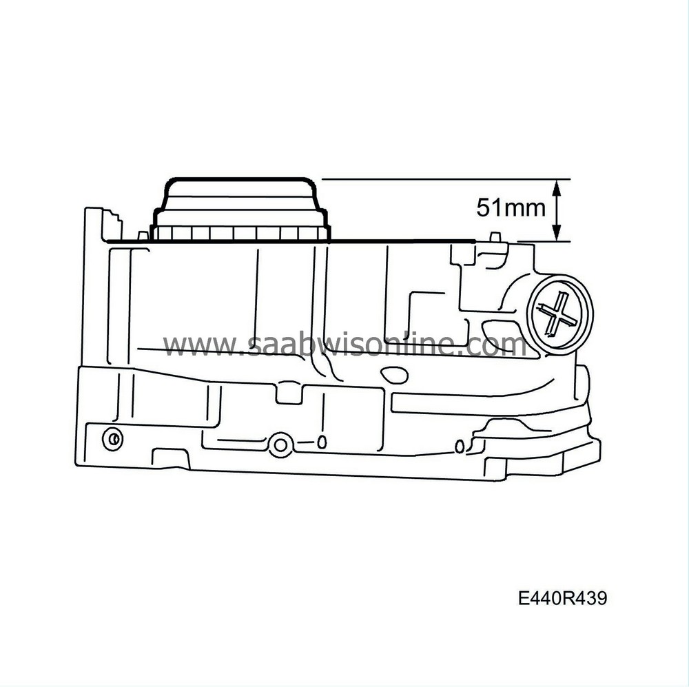
Make sure the ring gear and clutch C1 have fallen in place by measuring as illustrated. The distance must be approximately 51 mm.
|
|
34.
|
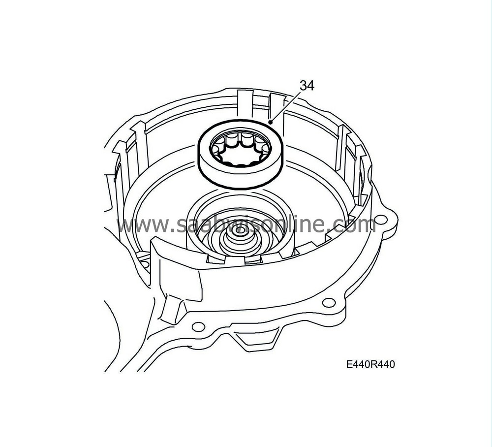
If the bearing has been removed, remove the small sealing ring and heat the bearing housing in the end plate using a heat gun for approx. 2 min. and fit the roller bearing. The text on the side of the bearing should face down. Insert the sealing ring.
|
|
35.
|
Fit the accumulator with spring and piston to the end plate.
|
|
36.
|
Blow the pipe clean, apply vaseline to the ends of the pipe and fit the oil pipe to the end plate. Make sure the O-rings are seated correctly on the pipe. Take care not to deform or damage the pipe. Use a splinter-free plastic mallet.
|
|
37.
|
Place the clips on the pipe and tighten the screws.
Tightening torque 5.5 Nm (4 lbf ft)
|
|
38.
|
Fit the seals to the bearing housing.
|
|
39.
|
Lubricate the O-rings with vaseline and fit the piston for brake B5 in the bottom of the end plate.
|
|
41.
|
Fit the plates for brake B3. Place the spring washer at the bottom with the concave side facing up.
|
|
42.
|
Fit the oil pipe and clip to the gearcase. Take care not to deform or damage the pipe. Use a splinter-free plastic mallet.
|
|
43.
|
Fit the bearing race for the rear cover into the end plate. Lubricate the bearing race with vaseline. Lay the bearing race and the thrust bearing in the C1/C2 unit.
|
|
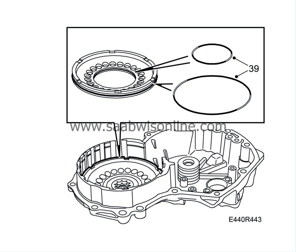
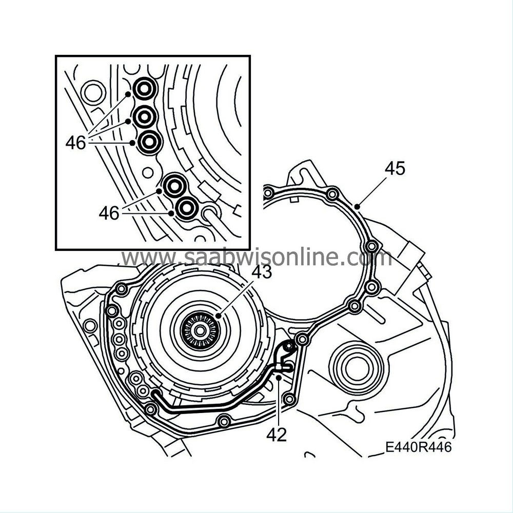
46.
|
Lubricate five new sealing rings for the oil holes with vaseline and fit them to the gearcase.
|
|
48.
|
Turn the gearbox through 180°.
|
|
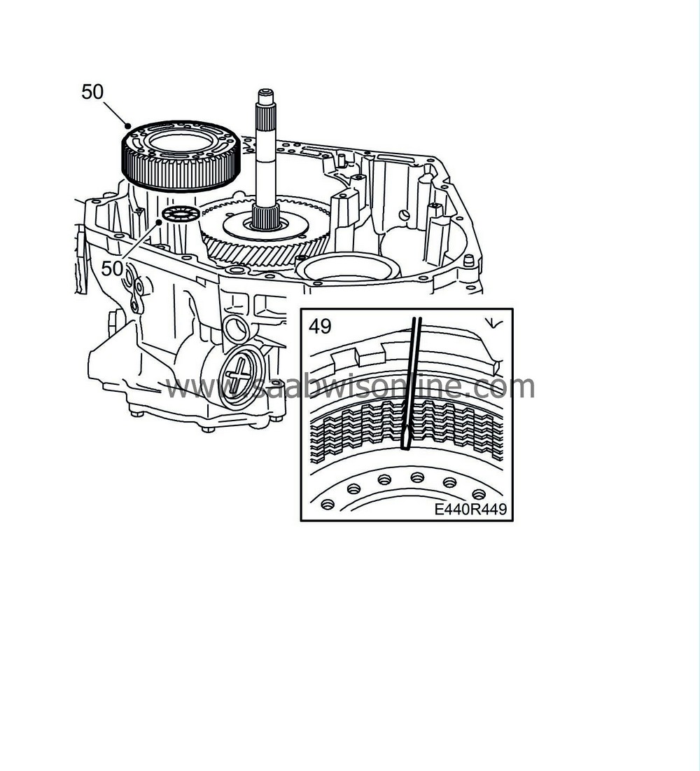
49.
|
Align the teeth on the plates for brake B5 using a screwdriver.
|
|
50.
|
Check that the two plastic washers are correctly positioned. Then fit planetary gear P4 and the ring gear with thrust bearing as a unit into brake B5.
|
|
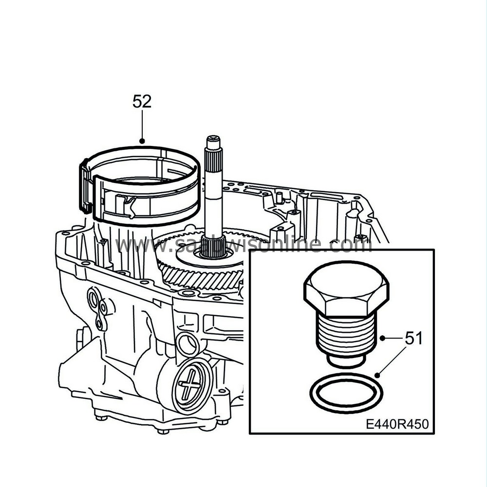
51.
|
Lubricate the O-ring for the hold-down bolt with petroleum jelly and tighten it.
Tightening torque 140 Nm (104 lbf ft)
|
|
52.
|
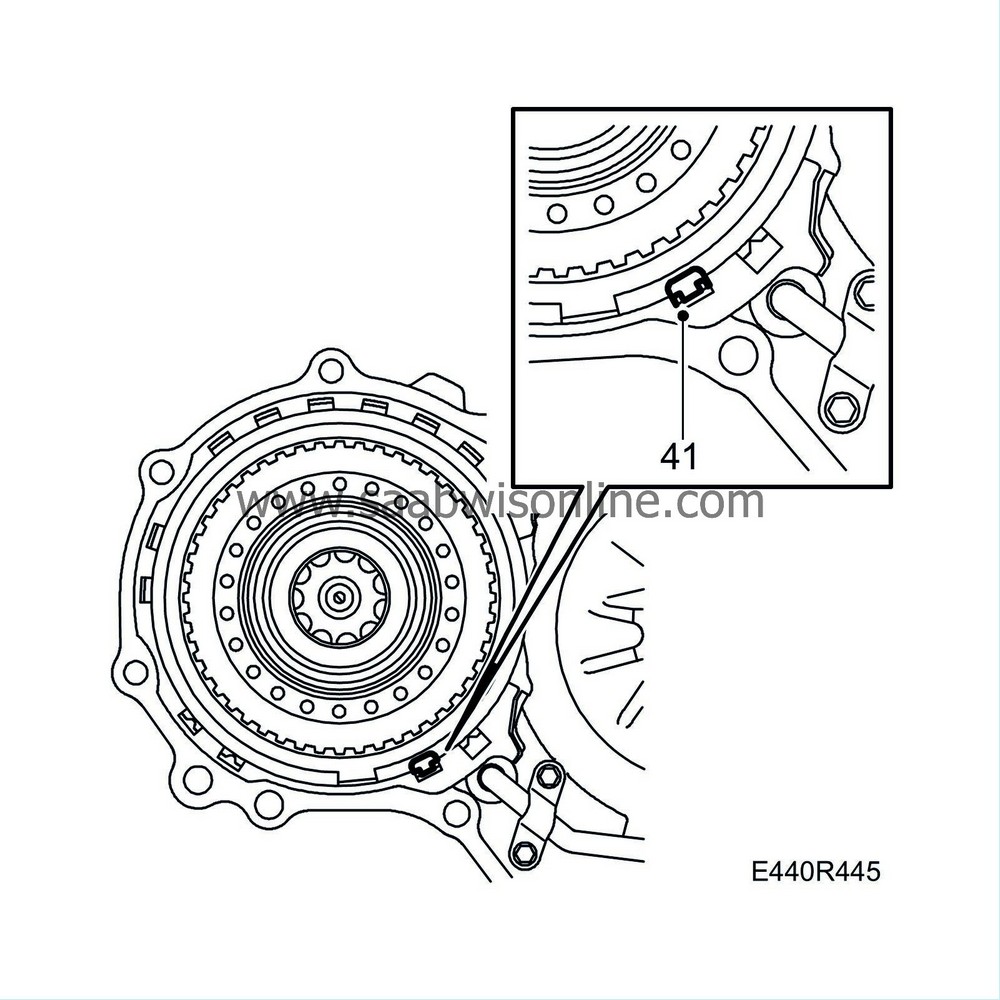
Oil in the brake band for brake B4 with automatic transmission fluid. Fit the brake band and the anchor bolt pin in the brake band recess.
|
|
53.
|
Insert the thrust bearing.
|
|
54.
|
Fit clutch C3 into the gearcase. Lift the brake band slightly to facilitate fitting.
|
|
55.
|
Align the teeth of the C3 clutch using a small screwdriver.
|
|
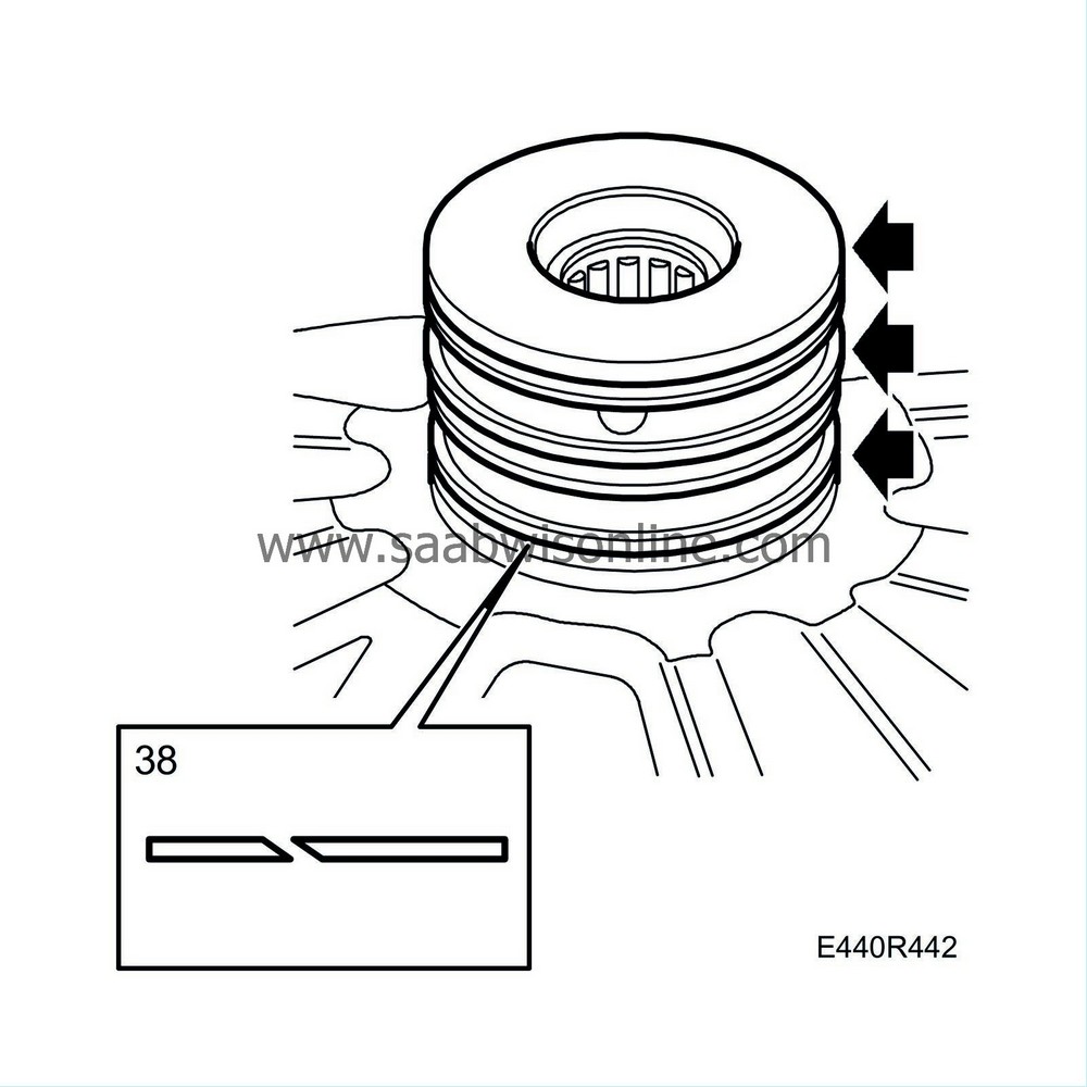
56.
|
Fit the sealing rings to the output shaft. Lubricate the sealing rings with vaseline.
|
|
57.
|
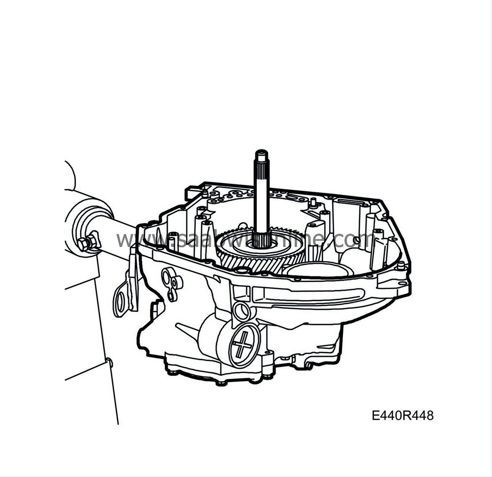
Align the plates using a screwdriver and fit the output shaft complete with clutch unit C3. Make sure that the shaft falls into place at the same height as the intermediate gear. Check that the shaft and gear rotate freely. Fit a bolt to the shaft to rotate it.
|
|
58.
|
Fit the thrust bearing race and the thrust bearing on the output shaft unit.
|
|
59.
|
Fit the spring and bolt. Place the ratchet on the correct side of the spring.
Tightening torque 5.5 Nm (4 lbf ft)
|
|
60.
|
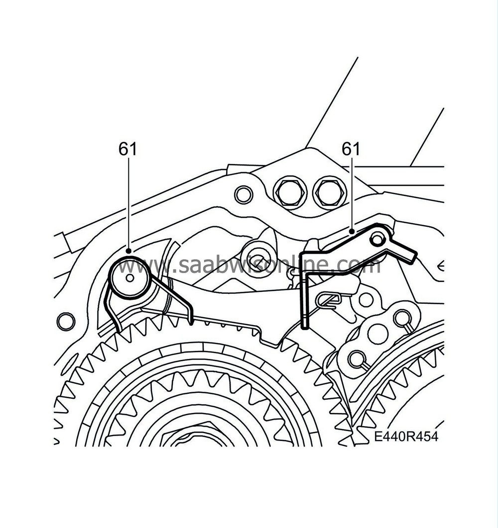
Fit the guide pin in the hole.
|
|
61.
|
Position the guide fork and the ratchet axle and spring.
|
|
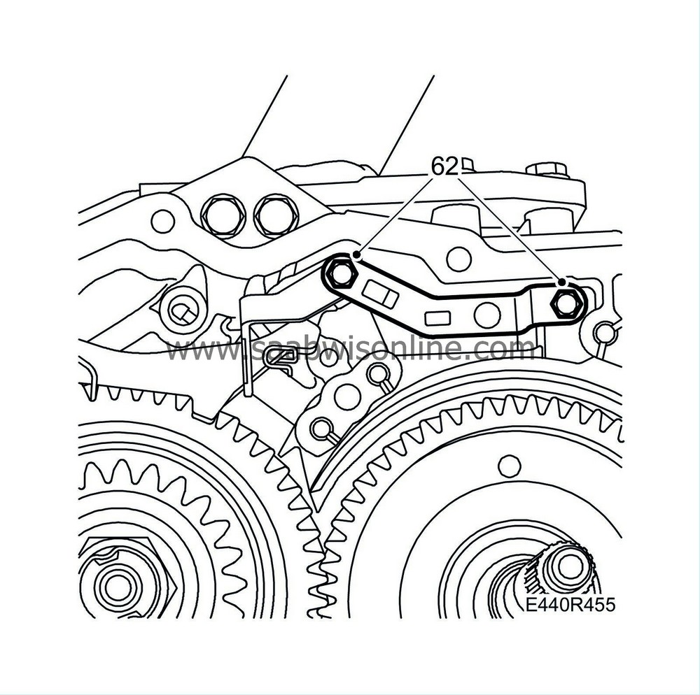
62.
|
Fit the ratchet sector gear position spring. (Note the different bolt lengths.)
Tightening torque 5.5 Nm (4 lbf ft)
|
|
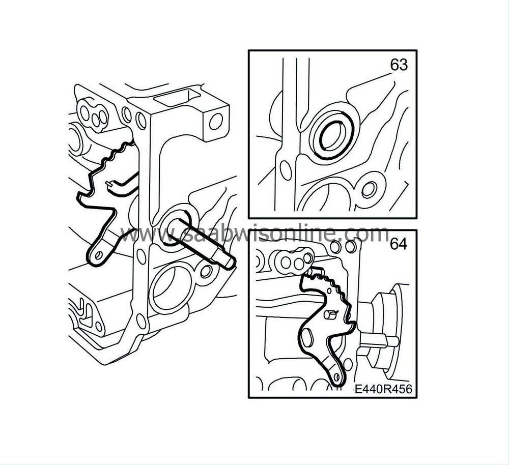
63.
|
Press in a new seal into the gearcase. Lubricate the lips of the oil seal with automatic transmission fluid.
|
|
64.
|
Fit together the control rod and the ratchet sector and slacken the spring. Make sure the handbrake detent falls into position and is in working order. Put the selector lever in neutral.
|
|
65.
|
Blow the pipe clean, apply vaseline to the ends of the pipe and fit the oil pipe and clip. Take care not to deform the pipe. Use a splinter-free plastic mallet.
|
|
66.
|
Fit the oil duct plate to the gearcase (short bolts). Tighten the bolts.
Tightening torque 5.5 Nm (4 lbf ft)
|
|
67.
|
Fit the cover with two bolts.
Tightening torque 5.5 Nm (4 lbf ft)
|
|
68.
|
Fit a new oil strainer and tighten the bolts. Make sure the seals are positioned correctly, one on each side.
Tightening torque 5.5 Nm (4 lbf ft)
|
|
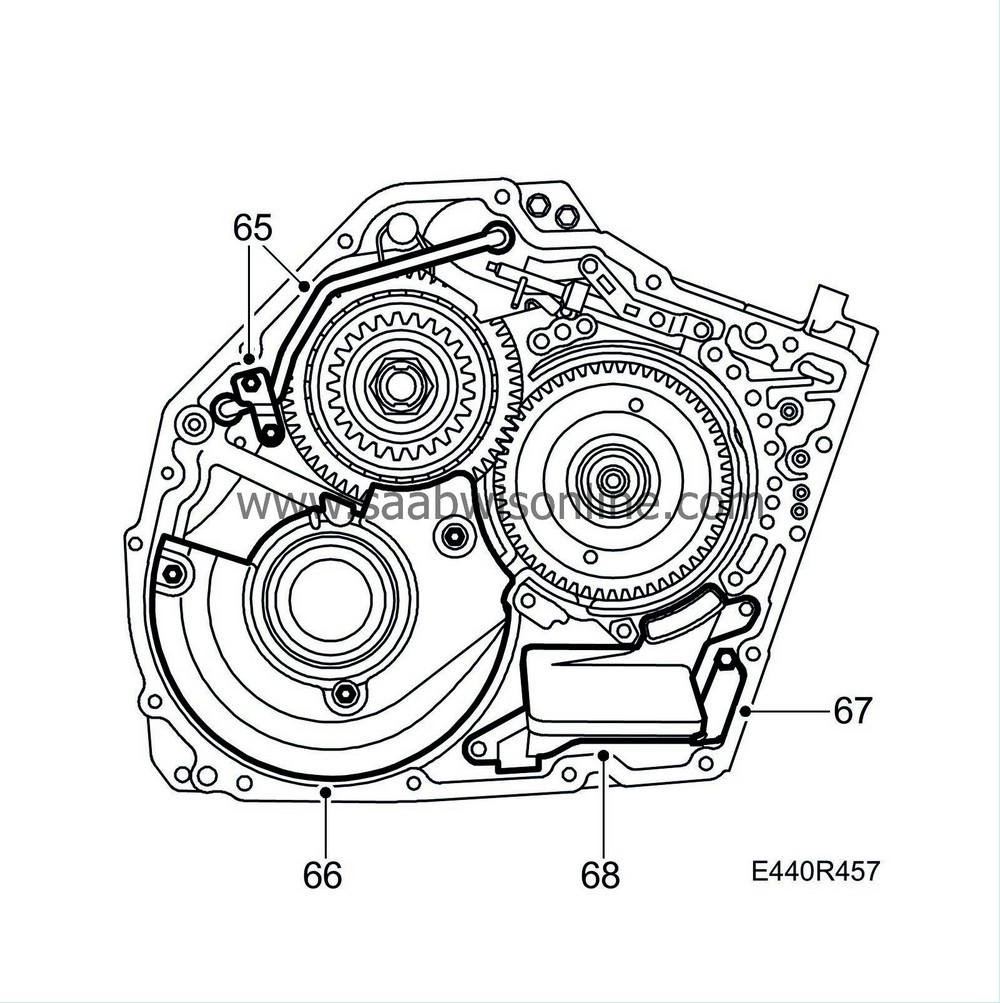
69.
|
Fit the differential housing unit.
|
Important
|
|
Inspect the inside of the differential housing for damage. Check also the surfaces of the drive shafts.
|
|
|
|
|
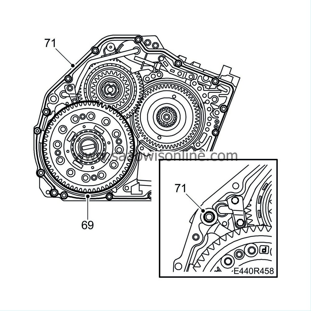
71.
|
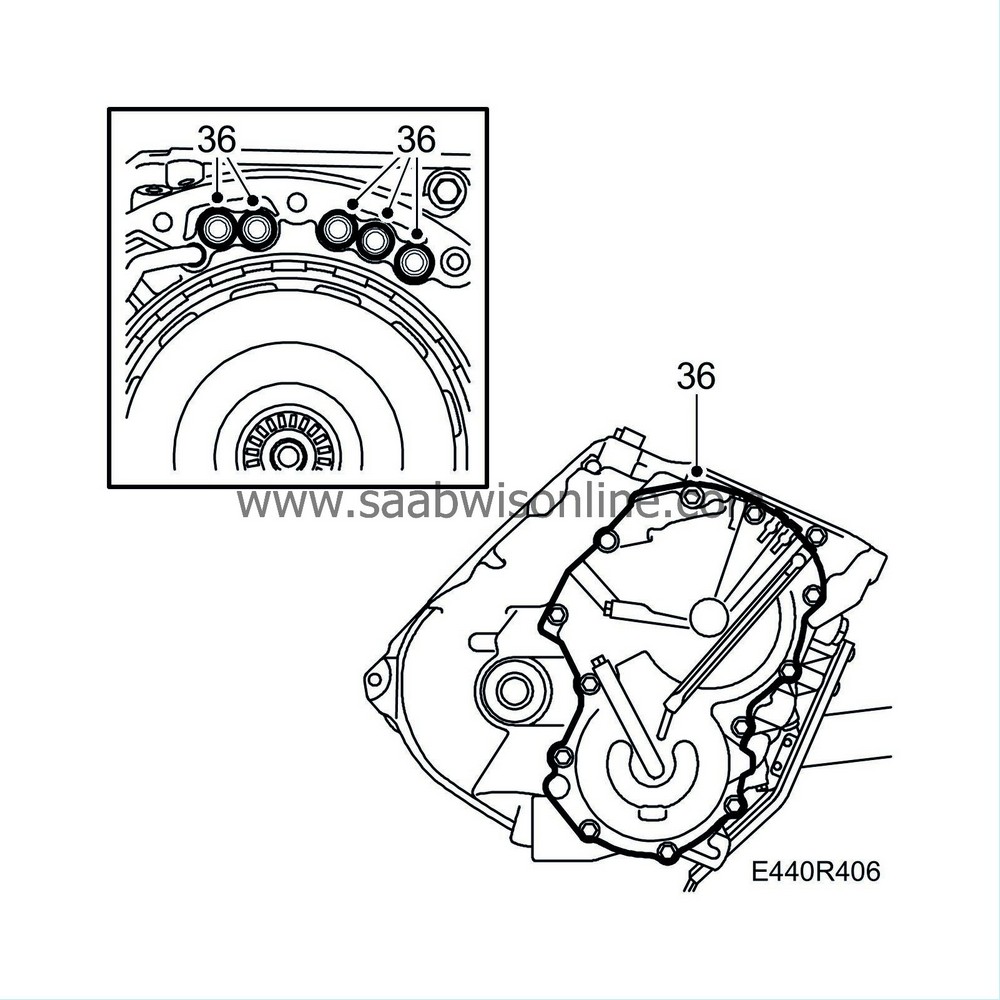
Fit a new seal into the gearcase and apply an approx. 1 mm thick bead of
87 81 841 Silicone flange sealant
to the gearcase as illustrated. Fit the torque converter housing.
|
|
73.
|
Clean the magnetic surface on the drain plug and fit it with a new gasket.
Tightening torque 40 Nm (30 lbf ft)
|
|
74.
|
Turn the gearcase so that the shaft points approx. 45° downward.
|
|
75.
|
Apply vaseline to the O-ring for the oil pump unit. Align the plates using a small screwdriver. Insert the thrust washer greased with vaseline into brake B1.

|
|
76.
|
Fit freewheel F1 and the bearing race for brake B1 and B2 to the oil pump unit. Lubricate the thrust washer for F1 with vaseline and fit it.

|
|
77.
|
Place the oil pump unit so its bolt holes are aligned with those in the gearcase. Press the pump unit in place carefully. Tighten the bolts carefully and alternately.
Tightening torque 25 Nm (19 lbf ft)
|
|
78.
|
Turn back the gearcase 45°
|
|
80.
|
Fit the two sealing rings.

|
|
81.
|
Connect the manual valve connecting rod to the manual valve control on the valve body unit. Screw in the bolts loosely. Take care not to fold the gasket.
|
|
82.
|
Fit the gasket on the cover, fit the cover bolts. Tighten all the valve body bolts alternately.
Tightening torque 10 Nm (7 lbf ft)
|
|
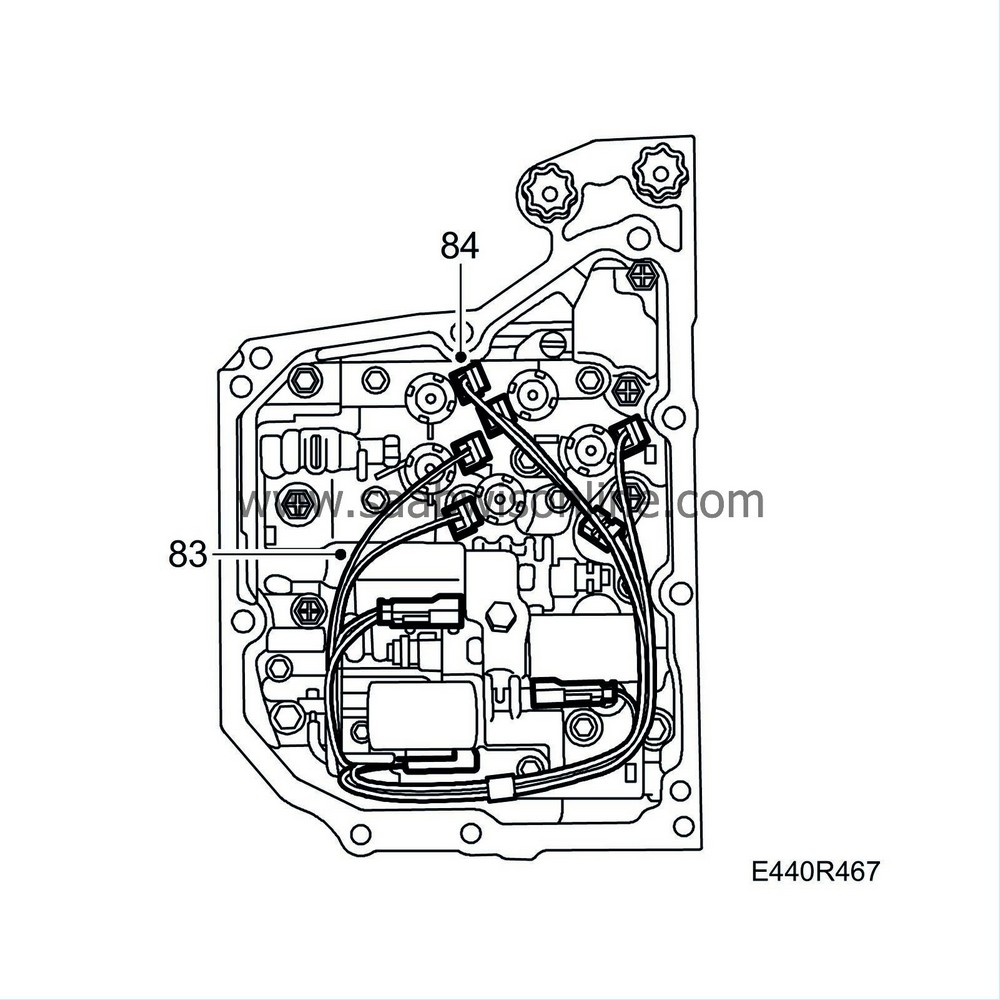
83.
|
Apply petroleum jelly to a new O-ring and fit it together with the cable grommet and the wiring harness for the solenoids on the gearcase.
|
|
84.
|
Plug in the connectors for the eight solenoids and fit the oil temperature sensor.
|
|
87.
|
Turn the gearbox 180°
|
|
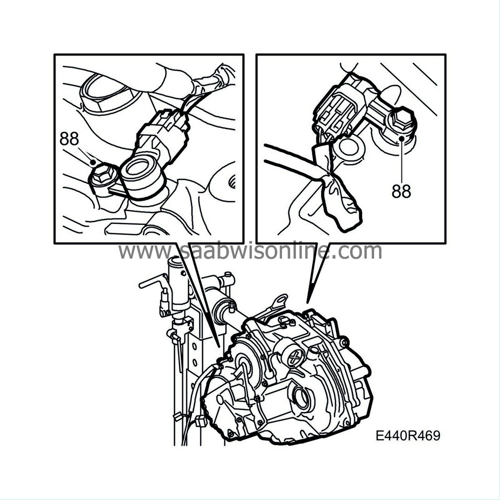
88.
|
Fit new O-rings to the speed sensors. Clean the speed sensors and make sure that there is no swarf on the magnets. Grease the O-rings with vaseline and apply thread sealant to the bolts. Fit the two speed sensors. Tighten the bolts.
Tightening torque 5.5 Nm (4 lbf ft)
|
|
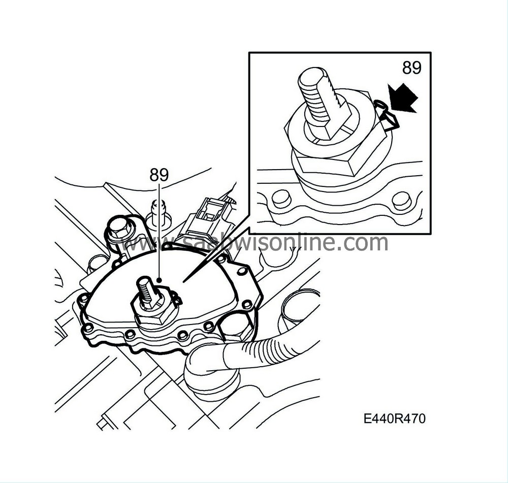
89.
|
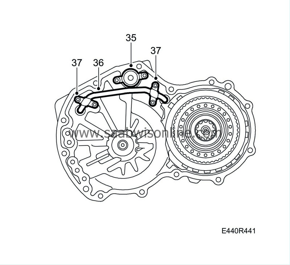
Fit the gear selector position sensor. Fit the holder for the cable grommet. Tighten the bolts on the gear selector position sensor first (important). Then tighten the nut on the gear selector position sensor and bend up the lock washer.
Tightening torque 8 Nm (6 lbf ft)
|
|
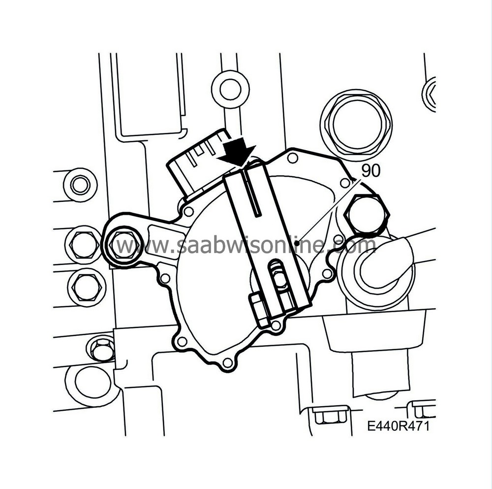
90.
|
Engage neutral and fit
87 92 467 Adjustment tool, gear selector position sensor
. Undo the bolts for the gear selector position sensor and adjust it so that the line is visible in the centre of the groove in the setting tool. Tighten the bolts.
Tightening torque 25 Nm (18 lbf ft)
|
|
91.
|
Remove the adjustment tool.
|
|
92.
|
Change the torque converter seal, see adjustment/replacement Torque converter seal.
|
|
94.
|
Make sure the torque converter has been fitted in the correct position and lay a steel rule on the mating face of the torque converter. Measure the distance between the mating face and the drive plate contact surface on the torque converter. The distance must be at least 15 mm.
|
|
97.
|
Remove the gearbox from the stand. Remove the holder from the gearbox.
|
|
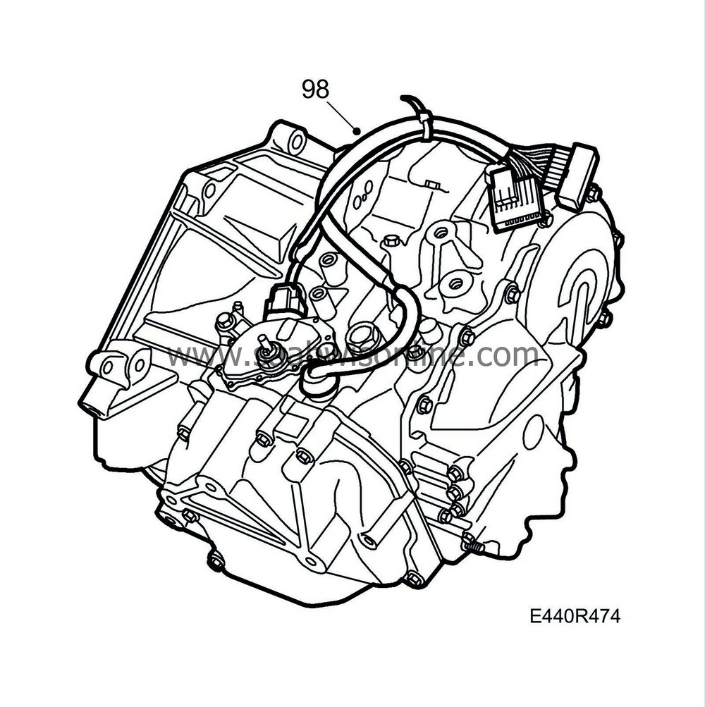
98.
|
Plug in the connectors to the gear selector and speed sensors.
|
|
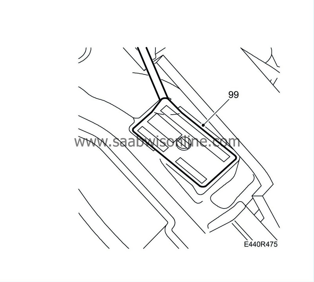
99.
|
Prise off the type plate from the changed case using a screwdriver.
|
|
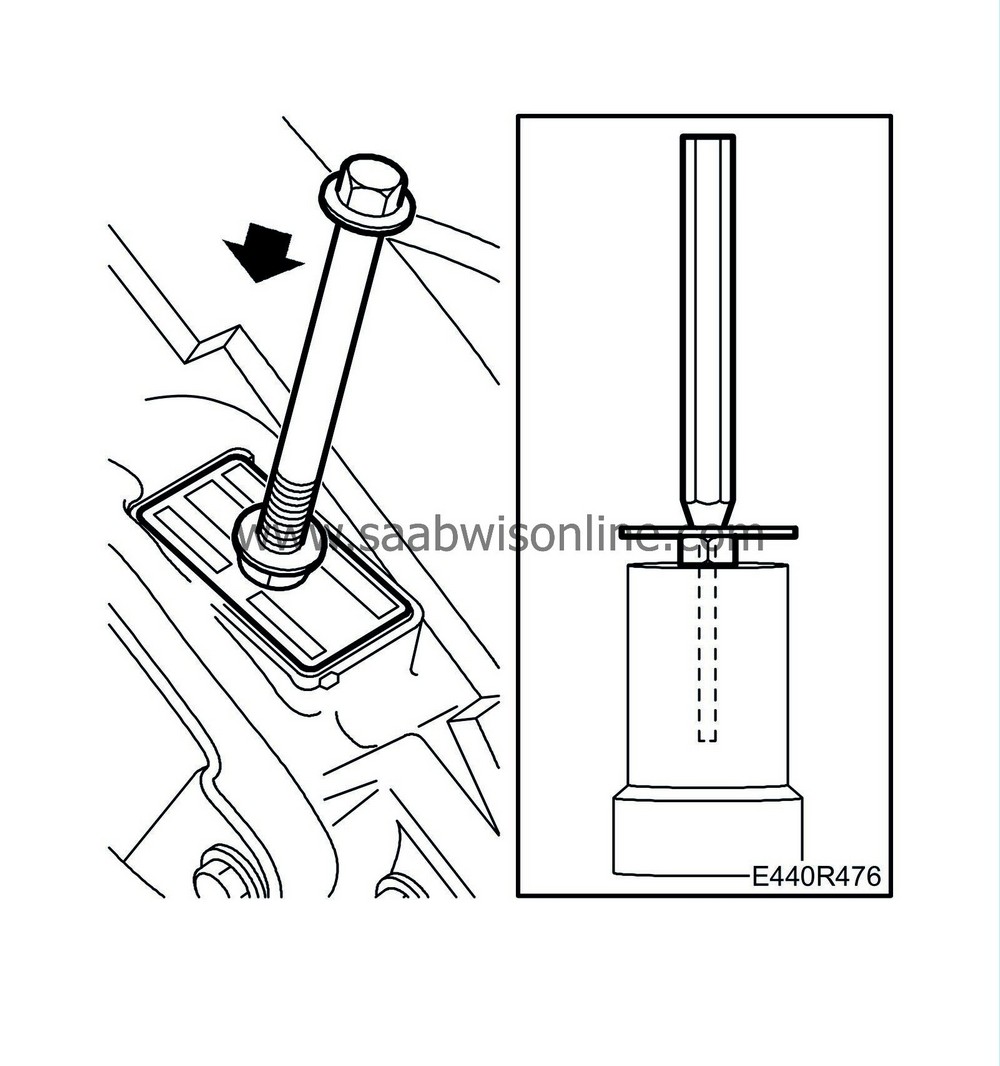
100.
|
Straighten the plate with a hammer. Widen the hole with a tapered drift and an M10 nut for support. Lay the plate on the new gearcase and press it on. Use an M8 nut for support over the centre pin and seal with a hammer.
|
|
101.
|
Fit the gearbox in the car. See To fit, Complete automatic transmission. Remember to clean the oil cooler with
87 91 824 Flushing equipment
.
|


